

Ganz digimaster DR-4FX1, digimaster DR-8FX2, digimaster DR-16FX2, digimaster DR-8FX5, digimaster DR-16FX5 Operation Manual
1
(FW Version 1015xx)

2
CONTENT
MONITORING ARCHIVING
3 Start up / Shutdown 59 To start the Archive menu
5 Live Screen At a Glance
SYSTEM SETTING WEB VIEWER
12 To move to the System Setup menu 62 What is the Web Viewer?
13 Camera Setting 64 Live
19 Display Setting 68 Search
24 Audio Setup 70 Setup
25 User Setting
27 Network Setup
30 System Setting
34 Storage
37 Event Setup
RECORD SETTING MOBILE VIEWER
46 To start the Record Setup menu 82 GanzView
47 Record Setup
SEARCH ARCHIVE VIEWER
52 To move to the Search menu while 94 Getting started with the Backup Play
in monitoring 95 Backup Player At a Glance
52 To move to the Search menu while
in playback mode
PLAY APPENDIX
56 If you want to play 98 Specification
3
Monitoring
Start Up/ Shutdown
START
You can connect DVR to a PC in the same network and control or manipulate it on the PC monitor.
1. Connect the adaptor to the 12VDC power input port in the rear panel of DVR.
Make connection when the power is not applied yet.
2. Connect AC cable to the power source. With a beep, the logo screen appears several
seconds after the front LED turns on.
3. When the booting process is completed, the live screen then the login screen appears.
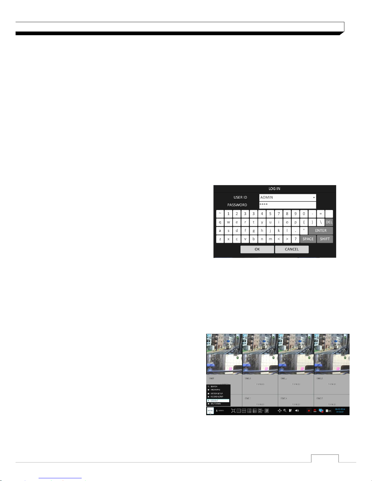
Log In
To manipulate or access the menus of DVR, you should have logged in.
1. When the system starts, the login screen appears.
2. Select a user and provide the password.
The default password of the "ADMIN" account is
"1234".
3. Click <OK>.
If the login information is correct and valid, you will
see the live screen.
For safe and secure use of the product, change
the password after purchasing.
.
Log Out
To prevent unauthorized access, it is recommended to log out when you leave the screen.
Hover the cursor near the bottom of the screen to display the menu.
1. In the monitoring screen, click <MENU> in the
bottom left corner of the screen to <LOG OUT>,
or press the [LOGOUT] button on the remote
control.
2. While logged out, Search / Backup /
System Setup / Record Setup / System Shutdown
menus are restricted to use.
4
Monitoring
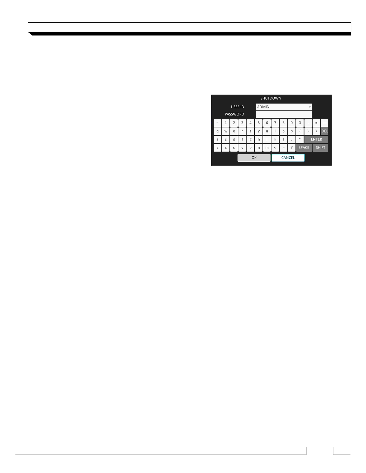
System Shutdown
You can connect DVR to a PC or mobile device in the same remote network and control or
manipulate it on the monitor of the PC or mobile device
1. In the monitoring screen, click <Menu> in the
bottom left corner of the screen to <SHUTDOWN>
the system, or press the [POWER] button on the
remote control.
2. Use the virtual keyboard to enter the password.
3. Be sure to disconnect the power in the rear panel.
If you turn off the system in an abnormal manner such as removing the power cord while the
system is in operation, the disk will have or increase the bad sectors, causing data loss and
shortened life cycle of the disk.
5
Monitoring
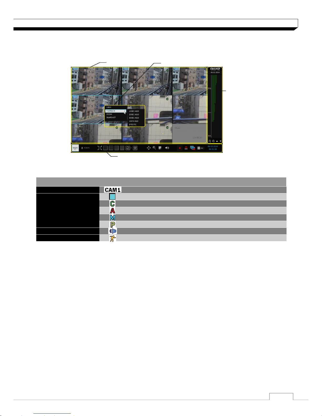
Live Screen At a Glance
The live screen largely consists of three components: video window, status bar and timeline zone.
Video Window
Icons used in the video window.
ITEM
Description
Camera ID
Show the camera ID
Record Mode Icons
Displayed if an event recording is reserved.
Display the status of the continuous recording.
Display the recording status when an alarm occurs.
Display the recording status when a motion event occurs..
Display the status of the emergency recording..
Audio Icon
The audio signal of the connected camera is outputting.
Motion Detection Icon
A motion is detected by the connected camera.
Status Bar
Timeline
Quick Menu
Video Window
6
Monitoring
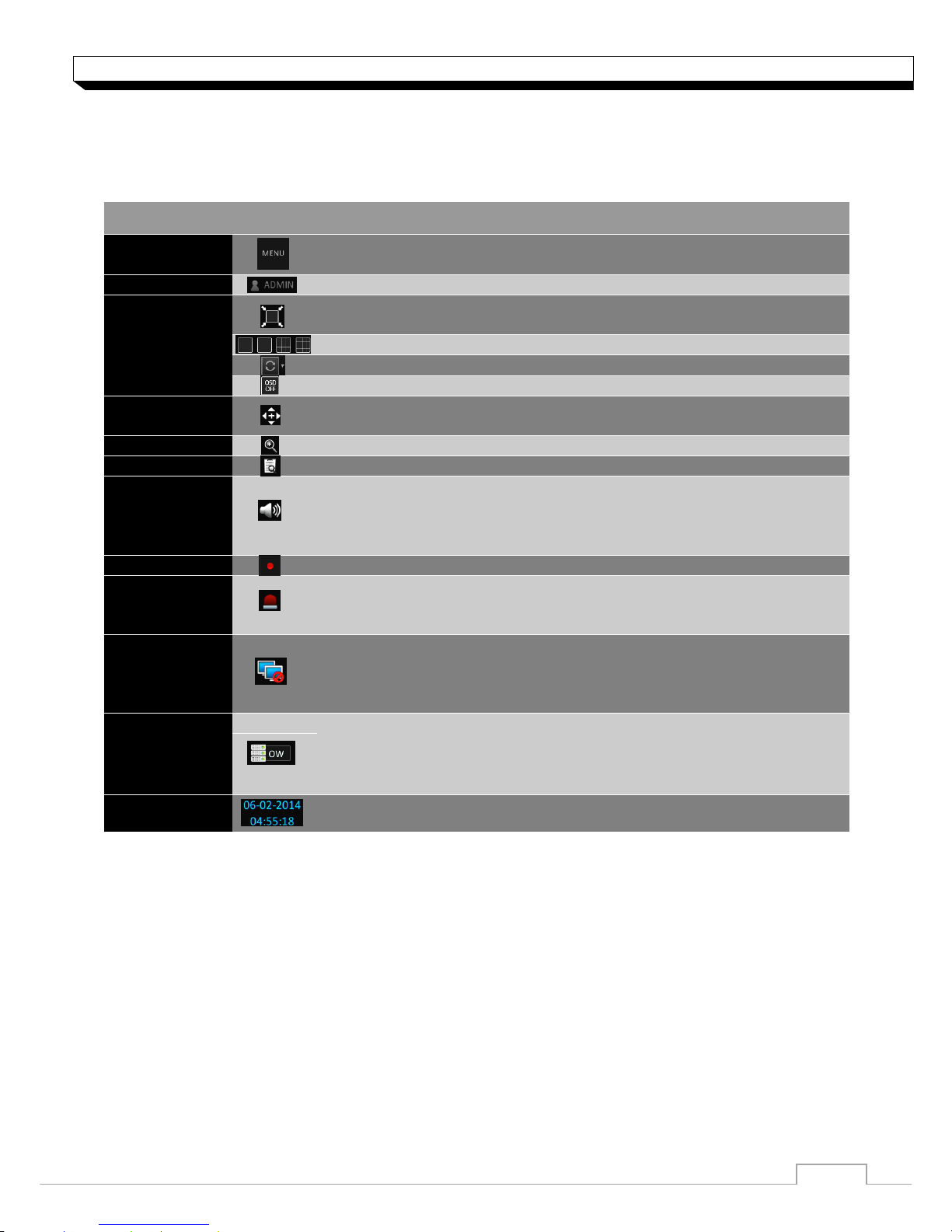
Status Bar
Press the ▼ button on the remote control, or place the mouse in the lower area of the screen to
display the status bar.
ITEM
Description
Menu Button
Select one of the system setup, search and backup menu items
before accessing it.
User ID
Show the ID of the user who has currently logged in.
Screen
Control
Buttons
Change the screen layout so that both status bar and timeline are
displayed at all times.
Select a split mode.
Select Auto Sequence or Special Split Mode.
Display or hide the OSD menu on the screen.
PTZ
Move to the PTZ screen. You can control the PTZ operations of a
PTZ-compliant camera on the PTZ screen.
Zoom
Move to the Digital Zoom.
Quick Log
Display the log list of the recent recording events.
Audio
Channel
Selection
Button
You can use the camera supporting the audio input to listen to the
audio.
Panic Record
Start the panic recording.
Alarm Indicator
Turns on if an event occurs. It does not turn on if no reaction to the
event is yet defined.
Click this to check the information of the event that occurred.
Network
Connection
Status
Check if network connection is made via an external PC or mobile
device. Click this to view the details of the concurrent users and to
check the network connection status. For more information, refer to
"Network Setup". (page 40)
Disk Space
Show the disk space information. If you have set the disk overwrite
mode, it will be displayed "OW" (Over Write) from the start point of
the overwriting. Click this to view the details of the disk status.
For more information, refer to "Record Setup".
Date & Time
Display the current time and date.
7
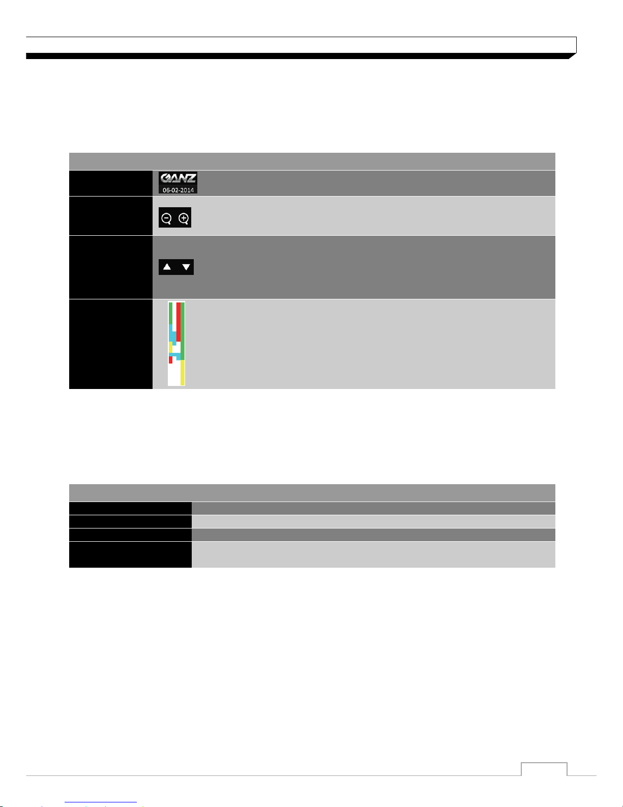
Monitoring
Timeline
Press the [▶] button on the remote control or move the cursor to the right of the screen to display
the timeline. Double-click the timeline to move to the video screen. Drag and drop it to make backup
or event search for the specified area.
ITEM
Description
Timeline Date
Display the date of the current timeline.
Click this to select a desired date of the timeline.
Expand/
Collapse
the timeline
Expand or collapse the timeline.
Navigation
through
Timeline
Navigate through the timeline.
You can also use the mouse wheel to do the navigation..
Timeline Bar
Display the recording data with time. The color of each bar indicates
the following:
Green : Continuous Recording
Red : Alarm Recording
Blue : Motion Recording
Yellow: Panic Recording
Quick Menu.
ITEM
Description
Channel No
Display the number of the current channel.
Play
Start playing the video of the selected channel from the specified time.
Zoom
Zoom the video of the selected channel.
Snapshot Capture
Capture the current live video and save it in the jpeg format.
Then, you can save the captured image in the USB device.
8
Monitoring
Using the status bar in the live mode
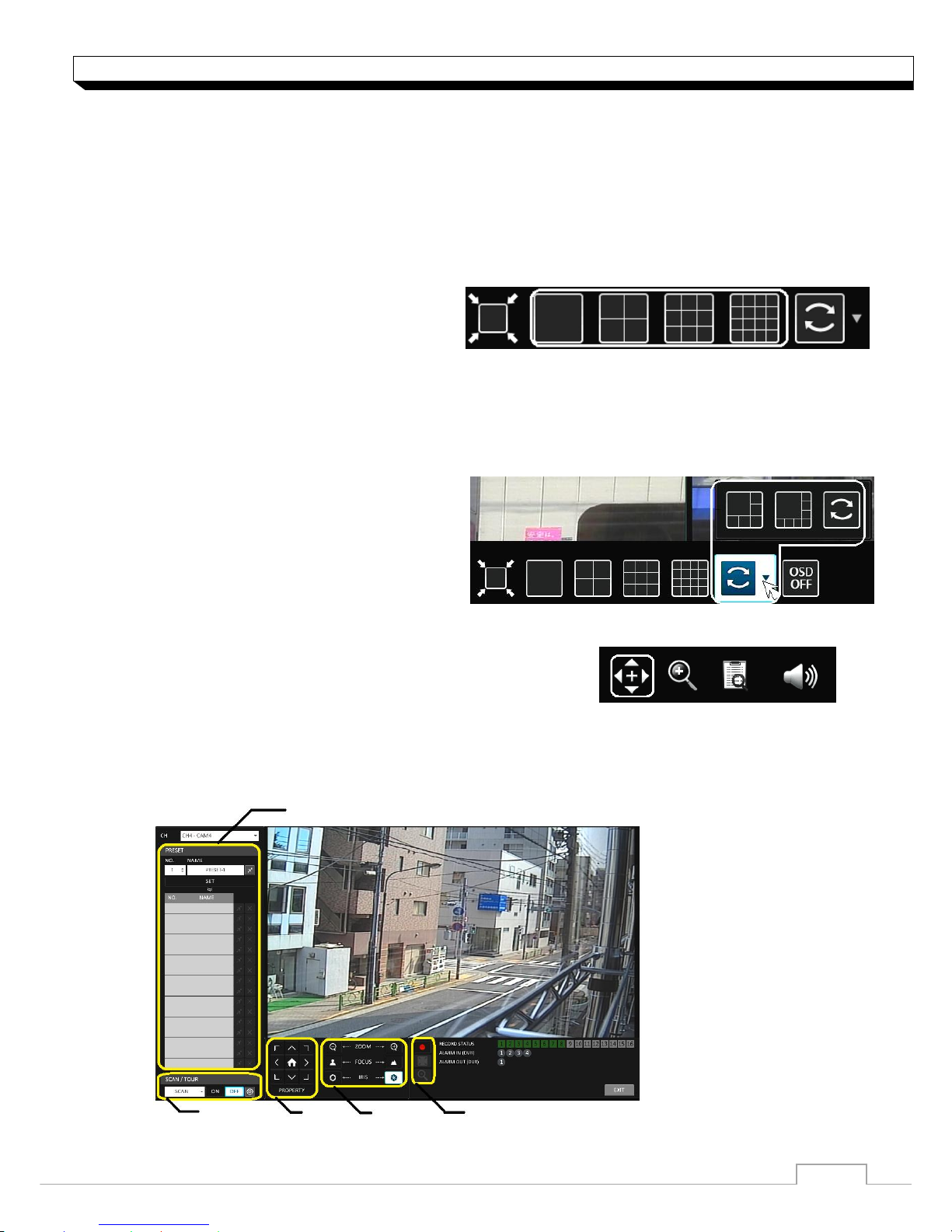
Selecting a split mode
Click a desired split mode from 1, 4, 9, 6, 8 and 16 split screen. Or press the [DISPLAY] button on
the remote control until a desired split mode is displayed.
4CH DVR model support only 1 and 4 split screen modes.
8CH DVR model does not support 16 split screen modes.
Auto sequence
Click the Sequence button in the status bar, or press the [SEQ] button on the remote control to
perform the specified sequence mode.
You can configure the sequence settings in <SEQUENCE>.
For details, refer to “Sequence”. (page 35)
Controlling PTZ
You can control PTZ cameras connected to each channel.
Use the mouse to click PTZ button on the status bar, or
press the [PTZ] button of the remote control to initiate
the predefined sequence.
In PTZ mode, use buttons on the screen to control PTZ or use [ZOOM], [FOCUS] and
[PRESET] buttons of the remote control.
Select Preset
Record/Screen Control/ Zoom
Zoom/Focus/Iris Adjustment
Move
SCAN/TOUR
Settings
9
Monitoring
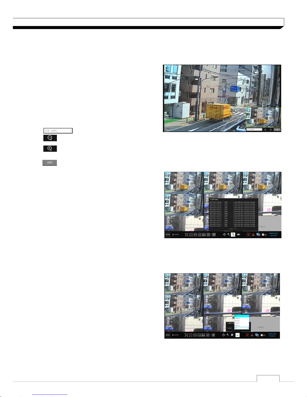
Digital Zooming
You can enlarge the monitoring screen for better view.
Zooming will enlarge the video of the selected channel. If no channel is selected, channel 1 will be
zoomed.
1. Click Zoom in the status bar or move the cursor
to a desired channel and right-click it to display
the context menu. Select <ZOOM>.
You can also press the [ZOOM] button on the
remote control.
2. Move to the zoom control screen. When the
menu bar appears in the right bottom, use the
buttons to control the zooming.
Select a channel to zoom in/out.
Zoom out the current (enlarged) image step by step.
Enlarge the current image step by step.
Zoom Box : Use the yellow box to move to or select a desired zooming area.
Exit the zooming screen and return to the live screen.
To check the event log
You can check the log of the events that occurred.
1. Click Log to display the “EVENT LOG” window.
The log list is sorted with the latest one on top.
2. Double-click a desired log to display the event
video.
You will move to the play screen of the selected
log.
To select an audio input channel
Select a channel from which the audio signal will be received.
>CHANNEL : Produces the selected channel’s
Audio, regardless of the split screen mode.
>LINK TO FULL SCREEN :When switching the
DVR display mode to view one channel, it
Produces the selected channel’s audio.
10
Monitoring
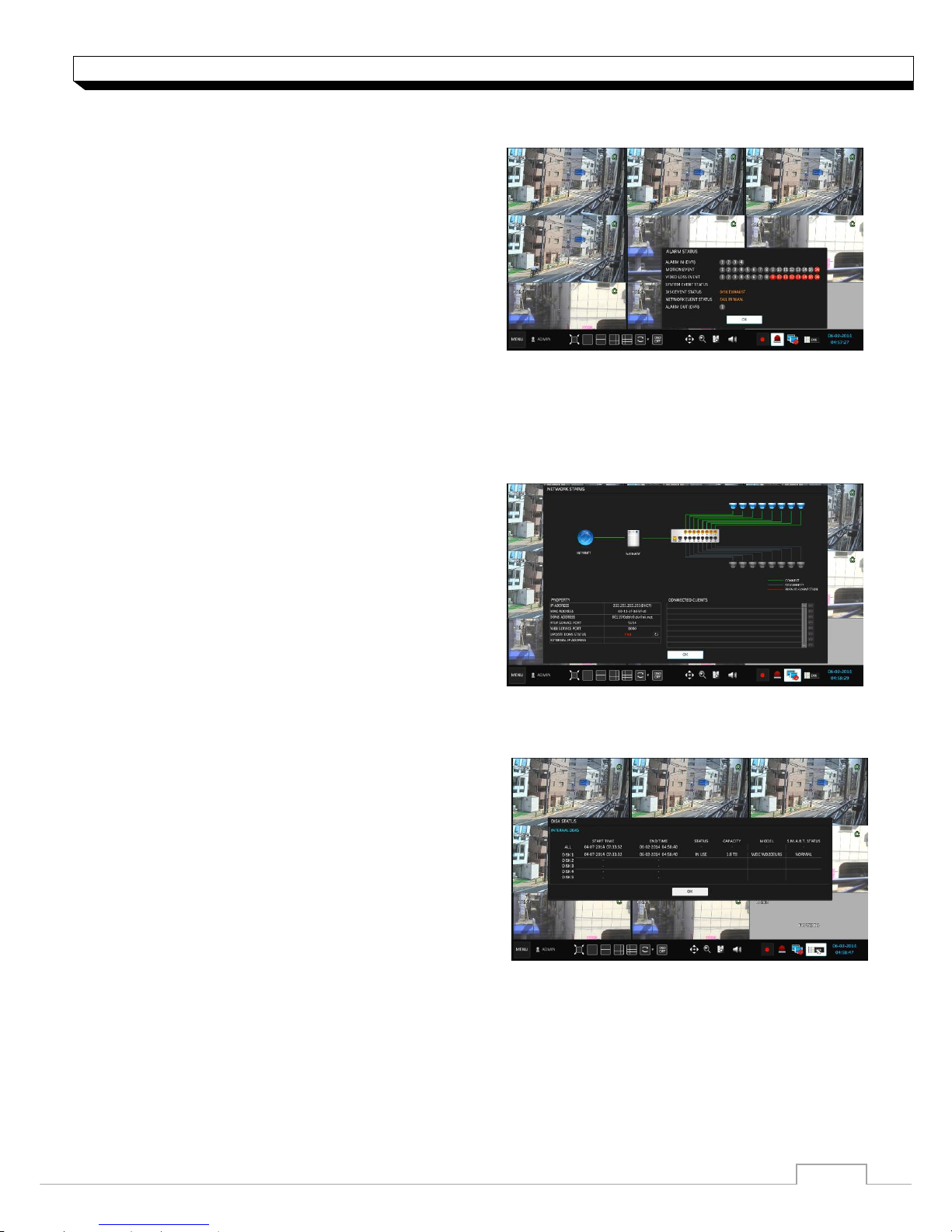
To check the alarm status
You can check the alarm status of each camera.
Click <OK> to close the window
To check the network status
Shows connection status of camera and network devices.
Click to display detailed information on current users and network connection
Click <OK> to close the window.
For more information, refer to "Network Status".
(page 40).
To check the disk status
You can check the storage space of the current disk
and check also if there is any problem with the disk.
Click <OK> to close the window.
For more information, refer to "Disk Information".
(page 47)
11
Monitoring
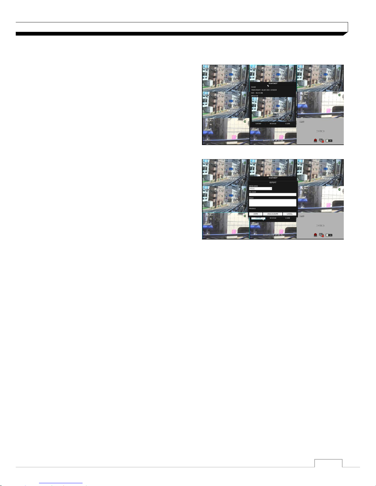
Saving captured snapshots
You can capture the current video screen and save or export to a connected storage device.
1. Select a channel first, and right click to open
pop up menu, and select
<SNAPSHOT CAPTURE>
menu item, or press the
[SNAPSHOT]
button of
the remote control.
2. Connect a storage device, and click <EXPORT>
button. To save the captured image onto the
built-in HDD, press the <RESERVE> button.
Saved image can be found in the “Archive>
Reserved data management” and can be
backed up.
3. Enter the <TAG NAME> and <MEMO> and press <BURN> or <ERASE & BURN> button
> A progress bar appears and indicates the progress of exporting to storage device.
> BURN : Snapshot is stored in the connected USB storage device.
> ERASE & BURN : Deletes all files in the connected USB storage and then saves
the snapshot.

12
System Setting
To move to the System Setup menu
How to use the mouse
How to use the remote control 1
How to use the remote control 2
.
13
System Setting
Camera Setting
You can configure the display settings of: camera title, covert option, motion and camera type
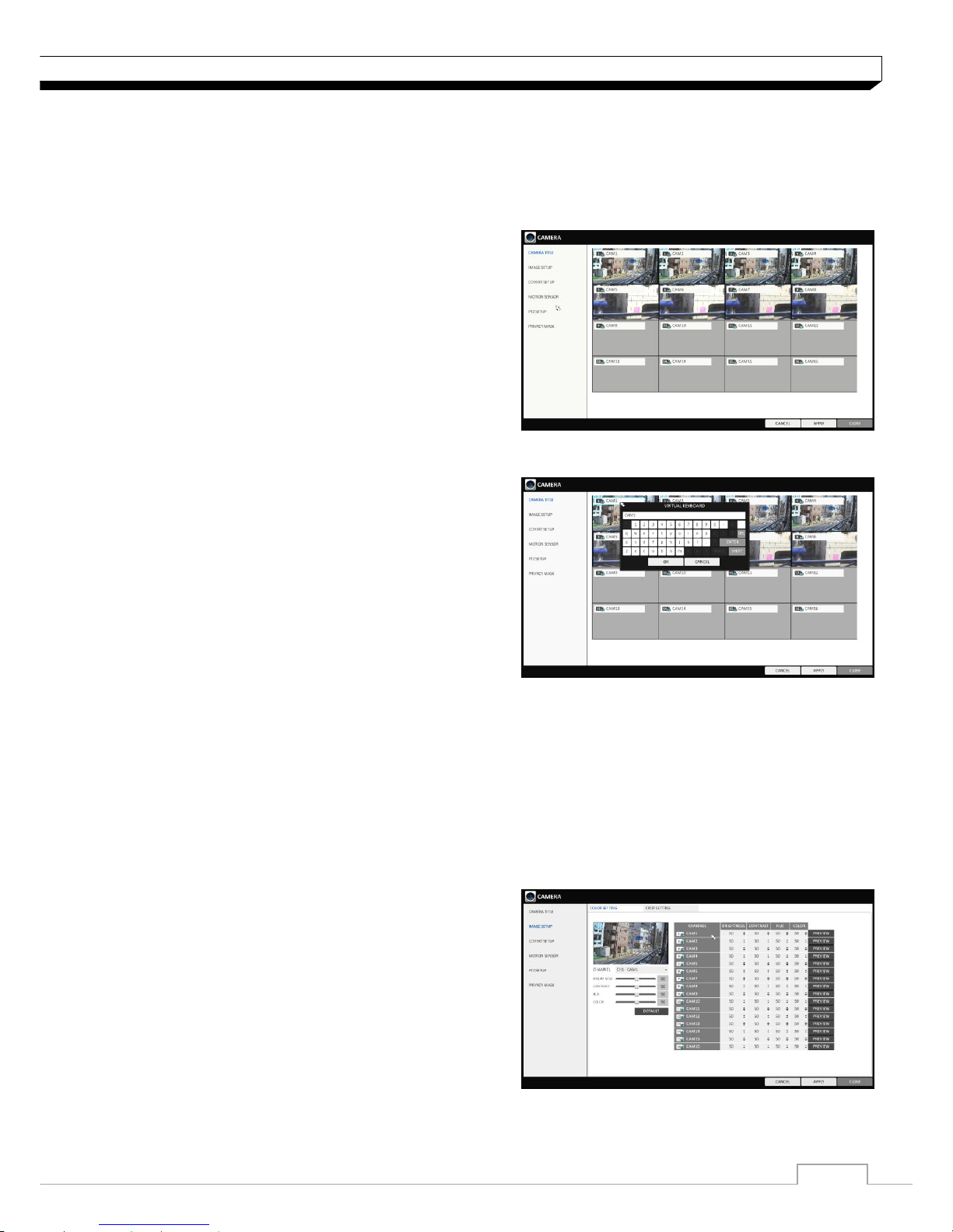
CAMERA TITLE
You can change the camera ID that is displayed on
the screen.
1. From <SYSTEM SETUP> - <CAMERA>, select
<CAMERA TITLE>.
2. Use the [▲▼◀▶/ENTER] buttons on the remote
control or use the mouse to select a channel that
you want to rename.
Alternatively, simply double-click the camera to
rename from the top left corner.
3. Once the virtual keyboard appeared, select desired
alphanumeric characters to complete your input,
and press the <OK> button.
The <SHIFT> key toggles letter case.
4. To apply the change, click <APPLY> in the bottom
of the screen.
5. When done, press the [EXIT] button on the remote
control or click <CLOSE> button.
The confirmation message appears and you will return to the previous menu.
Camera title allows up to 16 letters, combining numbers and upper/lower case alphabets.
Image Setup
You can adjust brightness, contrast, color and quality setting of each channel’s camera.
1. From <SYSTEM SETUP> - <CAMERA>, select <IMAGE SETUP>.
2. Use the [▲▼◀▶/ENTER] buttons on the remote
control or use the mouse to set each option of the
image menu.
3. To apply your changes, click <APPLY> button.
4. Once completed with setup, press [EXIT] button of
the remote control or click <CLOSE> button on the
bottom of the screen. A confirmation dialog appears
and returns to the previous menu.
Press <PREVIEW> button for adjusting with preview image.
14
System Setting
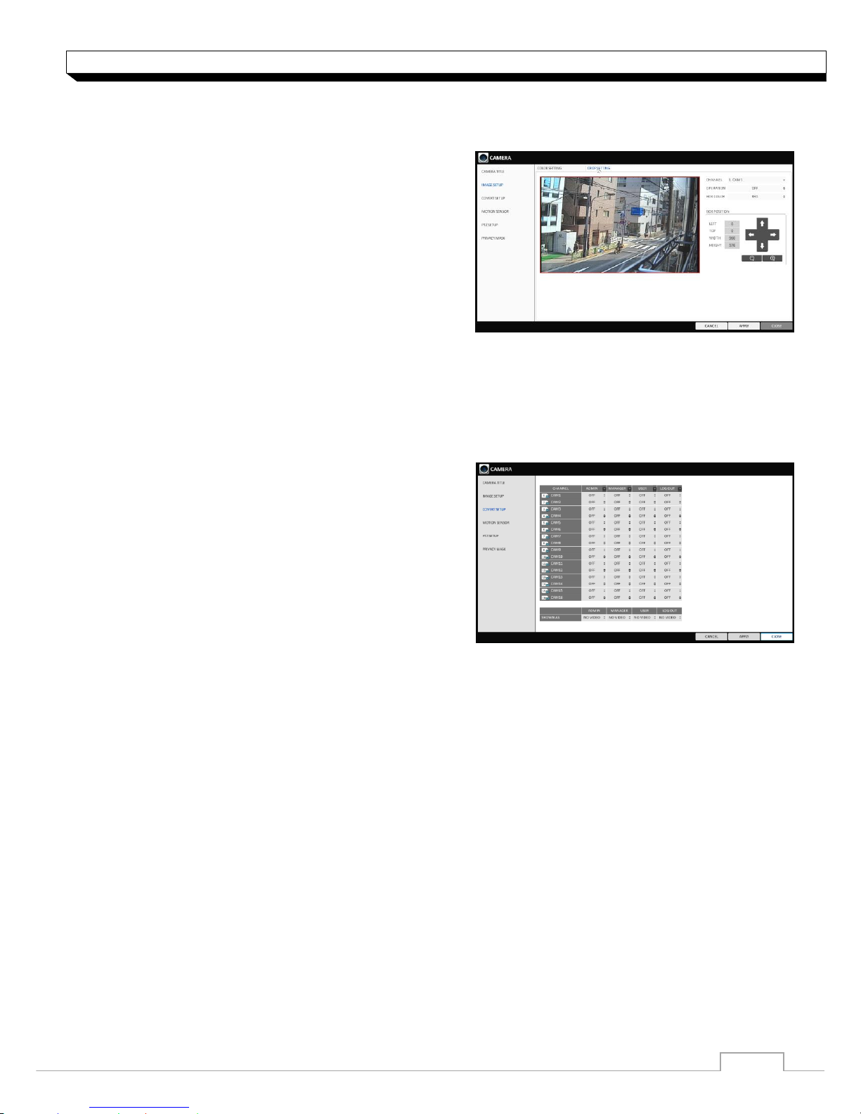
Crop Setting
You can cut out unnecessary region of channel’s video.
1. From <SYSTEM SETUP> - <CAMERA>, select
<IMAGE SETUP>-<CROP SETTING>.
>CHANNEL : Select the channel to set cropping
area.
>OPERATION : Set whether to use cropping or not.
>BOX COLOR : Select the box color to mark the
cropping area.
>BOX POSITION : Set position and size of the
cropping box.
2. To apply the change, click <APPLY> button.
3. When done, press the [EXIT] button on the remote control or click <CLOSE> button.
The confirmation message appears and you will return to the previous menu.
Covert Setup
You can set to hide the camera video so that
a specific user or user group cannot view.
Set a channel(s) that you want to hide from a specific
user or user group.
1. From <SYSTEM SETUP> - <CAMERA>, select
<COVERT SETUP>.
2. Use the [▲▼◀▶/ENTER] buttons on the remote
control or use the mouse to select a covert
channel(s) from a specific user group.
>ADMIN, MANAGER, USER : Set them to <ON>.
The selected channel will be hidden from the applicable user account.
>LOGOUT : Set it to <ON>. When the user logs out, the selected channel will not be displayed.
3. Select display title on live view screen for covert channel either “COVERT” or “NO VIDEO”
To activate this settings, user need to logoff then login DVR again.
4. To apply the change, click <APPLY> button.
5. When done, press the [EXIT] button on the remote control or click <CLOSE> button.
The confirmation message appears and you will return to the previous menu.
To change the covert settings from user group to user, move to the <USER> menu and make
necessary changes. (page 38)
15
System Setting
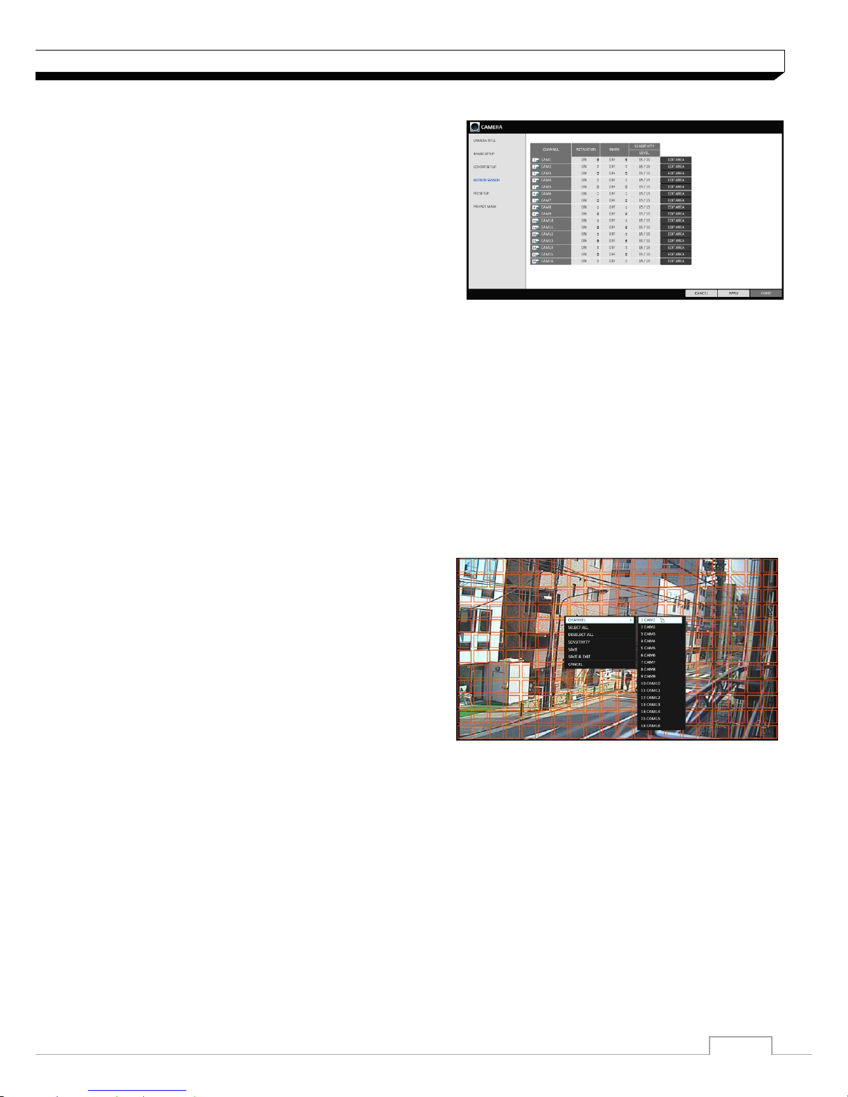
Motion Sensor
Set the motion sensor of the camera so that it can
detect a motion event.
1. From <SYSTEM SETUP> - <CAMERA>, select
<MOTION SENSOR>.
2. Use the [▲▼◀▶/ENTER] buttons on the remote
control or use the mouse to specify the use of each
option item.
> ACTIVATION : turn on or off the motion sensor.
> MOTION MARK: Set it to <On>.
The video window will display the motion mark if a motion is detected.
> SENSITIVITY : Set the sensitivity level of the motion sensor to either Daytime or Nighttime.
> EDIT AREA : Specify the motion detection area.
3. To apply the change, click <APPLY> button.
4. When done, press the [EXIT] button on the remote control or click <CLOSE> button.
The confirmation message appears and you will return to the previous menu.
The motion detection sensitivity may differ depending on the characteristics of the
connected camera or installation environment.
Motion Area Setup
From the motion setup window, click <EDIT AREA> in the right corner.
1. Click <EDIT AREA> to move to the motion
area setup screen.
2. If using the remote control, press the [ENTER]
button to mark the current position.
3. Use the arrow buttons to move to a desired block
and press [ENTER]. The area setup will begin.
Then, use the arrow buttons to specify the area.
Alternatively, you can use the drag-and-drop
method to specify or release the area using
mouse.
4. If you select the specified area again, it will be released.
5. Press the [EXIT] button on the remote control or
right-click any area to display the popup window
as in the right picture.
16
System Setting
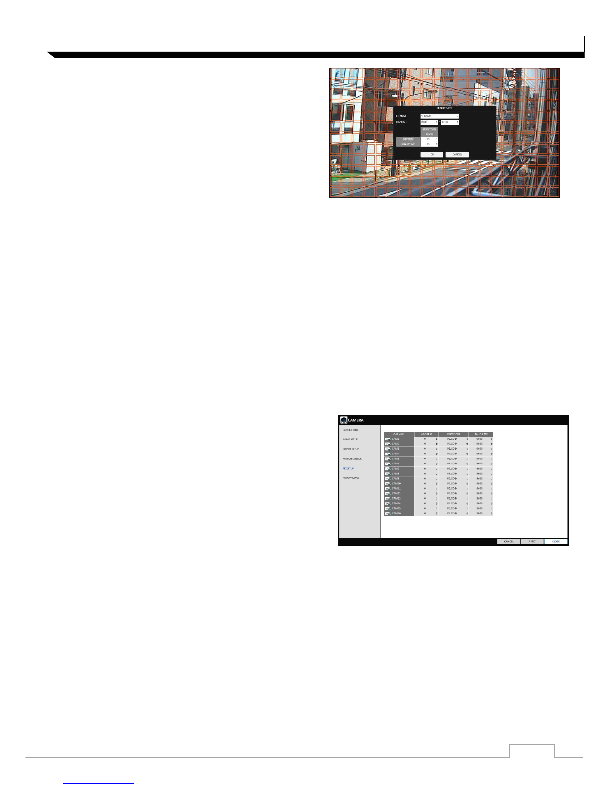
6. While the popup window is displayed, select
<SENSITIVITY> to set the detection sensitivity.
> CHANNEL : select a channel to set the motion
Sensitivity.
> SENSITIVITY : 1(Low) ~ 15(High) - The higher
the number is, the more higher the sensitivity
level becomes.
> DAYTIME : Specify the time period that will be
considered as daytime.
- DAYTIME : specify the <SENSITIVITY> for the daytime.
- NIGHTTIME : specify the <SENSITIVITY> for the nighttime.
Images recorded in a low contrast scene such as at night cause severe noise, triggering the
motion event too often.
If unwanted events occur frequently at night, you may want to reduce the motion
sensitivity for the night duty.
PTZ Setup
You can configure PTZ cameras connected to each channel. Set the camera ID, protocol, baud rate
and PTZ control speed for each channel.
1. From <SYSTEM SETUP> - <CAMERA>, select <PTZ SETUP>.
2.Use the [▲▼◀▶/ENTER] buttons on the remote or
mouse to set protocol and baud rate.
Refer to user’s manual of the PTZ the camera
or consult camera installer for further details
on PTZ settings, such as camera address,
protocol and baud rate.
3. To apply your changes, click <APPLY> button.
4. Once the setup completed, press the [EXIT]
button of the remote control or click <CLOSE> button
on a confirmation dialog. Click <CANCEL> to return to the previous menu.

17
System Setting
Privacy Mask
For privacy purposes, you can specify masking area for a selected camera’s video.
1. From <SYSTEM SETUP> - <CAMERA>, select <PRIVACY MASK>.
2. Use the [▲▼◀▶/ENTER] buttons on the remote or
mouse to set channels enabled, mask color and
its area.
> ACTIVATION : Turn on or off the privacy mask.
> MASK COLOR : Select the color of the masked
area, which will be displayed on the monitor.
3. To apply your changes, click <APPLY> button.
4. When done, press the [EXIT] button on the remote
control or click <CLOSE> button.
Privacy Mask Area Setup
You can specify privacy masking area.
1. From <AREA SETUP> tab on the right side.
2. When using the remote, press the [Select]
button to show the selector first.
3. Use direction key to move to the desired channel,
and the press the [Select] button to begin area
setup.
Use direction keys to set the masking area.
When using mouse, hold the mouse left button
and drag to set or cancel the masking area.
4. Selecting masked area again will exclude the
corresponding block from the masking area.
18
System Setting
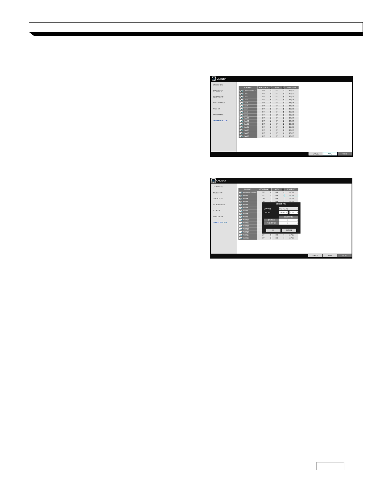
Tamper Detection (Available on DR-8/16FX5)
You can set to detect tampering attempt to interfere monitoring operations by tampering the installed
camera.
1. Select the <TAMPER DETECTION> form the
<CAMERA> menu items in <SYSTEM SETUP>.
2. Use the [▲▼◀▶/] buttons on the remote or the
mouse to select <MARK, SENSITIVITY> and
set the tampering detection condition appropriately.
3. For each channel, set the day/night sensitivity.
4. Set the activation of each channel, and set whether to display indicator on the screen.
>SENSITIVITY
-LEVEL : The detection sensor’s sensitivity for
each detection block. (Can be separately set
for day/night modes)
> ACTIVATION : Set the detection for each
channel to be enabled/disabled.
> MARK : Turns on or off the detection indicator
to be displayed on the screen
5. To apply your changes, click <APPLY> button.
6. When done, press the [EXIT] button on the remote control or <CLOSE> in the lower screen.
The confirmation message appears and you will return to the previous menu.
19
System Setting
Display Setting
You can configure the display settings regarding the OSD, sequence monitor and SPOT output.
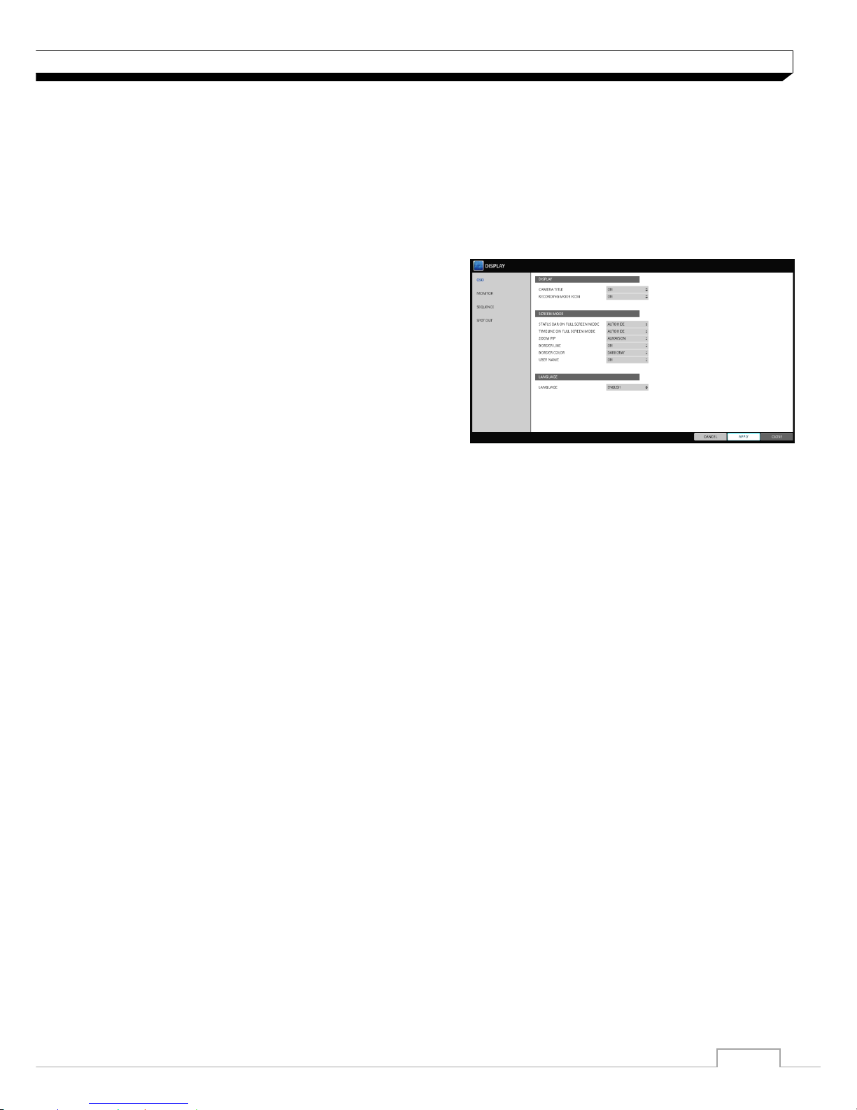
OSD
You can set Camera Name, Icon, Status Bar, Timeline, Borderline, User Name and Language
1. From <SYSTEM SETUP> - <DISPLAY>,
select <OSD>.
2. Use the [▲▼◀▶/ENTER] buttons on the remote
control or use the mouse to set each option of the
OSD item.
> CAMERA TITLE : specify the display of the
camera title on the screen.
> RECORDING MODE ICON : specify the display
of the record mode icon on the screen.
> AUDIO ICON : specify the display of the audio
icon on the screen.
> STATUS BAR ON FULL SCREEN MODE : select to show or hide the status bar in full screen
mode.
- AUTO HIDE : place the cursor in the lower area of the screen to display the status bar.
If moving the cursor up, the status bar will disappear.
- ALWAYS ON : The status bar will be displayed at all times.
- 5 SEC ~1 MIN : If no mouse movement is detected for from 5 seconds to 1 minute, the status
bar will disappear.
> TIMELINE ON FULL SCREEN MODE : select to show or hide the timeline in full screen mode.
- AUTO HIDE : place the cursor in the right corner to display the timeline. If moving the cursor to
the left, the timeline will disappear.
- ALWAYS ON : The timeline will be displayed at all times.
- ALWAYS OFF : The timeline will not be displayed.
> ZOOM PIP : Select to show or hide the Picture in Picture window on Digital Zoom.
-ALWAYS ON : PIP window will be displayed at all time.
-1/3/5 SEC : PIP window will disappear after selected time.
> BORDER LINE : specify the display of the cross-border between channels in a split mode
> BORDER COLOR : select a color for the border.
> USER NAME : specify the display of the currently logged-in users on the status bar.
> LANGUAGE : select a menu display language.
3. To apply the change, click <APPLY> button.
4. When done, press the [EXIT] button on the remote control or click <CLOSE> button.
The confirmation message appears and you will return to the previous menu.
20
System Setting
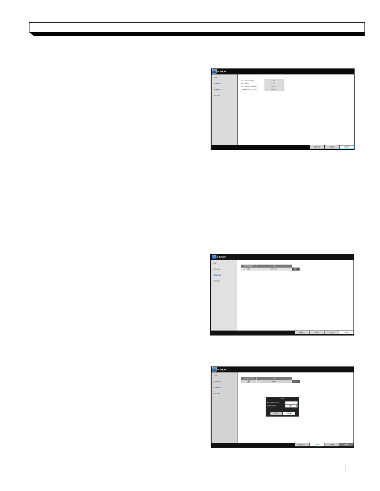
Monitor
If you change from monitoring mode to sequence, you will have to set the interval of the sequence.
1. From <SYSTEM SETUP> - <DISPLAY>, select
<MONITOR>.
2. Use the [▲▼◀▶/ENTER] buttons on the remote
control or use the mouse to set dwell for sequence
mode and SPOT Out dwell.
> SEQUENCE DWELL : Sets the time interval to
the next screen mode for Live monitoring, which
defines individual screen mode�s dwell time in the
Sequence. (Can set to 1 sec ~ 60 sec)
> SPOT DWELL : Sets the time interval to the next
view type, which defines individual view type’s dwell time for SPOT OUT. (Can set to 1 ~ 60sec)
> VIDEO ASPECT RATIO : Set aspect ratio for Live View image ( 16:9 / 4:3 ).
> DISPLAY RESOLUTION: Set monitor output resolution.
(Auto / 1920x1080 /1280x720 / 1280x1024)
3. To apply the change, click <APPLY> button.
4. When done, press the [EXIT] button on the remote control or click <CLOSE> button.
The confirmation message appears and you will return to the previous menu.
Sequence
Select a split mode for the sequence, and also select a list of active items when the sequence is
performed.
1. From <SYSTEM SETUP> - <DISPLAY>, select
<SEQUENCE>.
2. Use the [▲▼◀▶/ENTER] buttons on the remote
control or use the mouse to add a sequence or
change the settings of the existing sequence.
>ACTIVATION : Select a list that you want to
activate the sequence for.
Only one list will become active.
>ADD : add a sequence.
3. To apply the change, click <APPLY> button.
4. When done, press the [EXIT] button on the remote control or click <CLOSE>button.
The confirmation message appears and you will return to the previous menu.
To add a sequence
1. Click <ADD> in the bottom of the screen.
2. When the "ADD" dialog appears, enter a title using
the virtual keyboard.
3. Enter the name of the sequence and click <ADD>.
4. When the <ADD VIEW TYPE> dialog appears,
click <ADD>.
21
System Setting
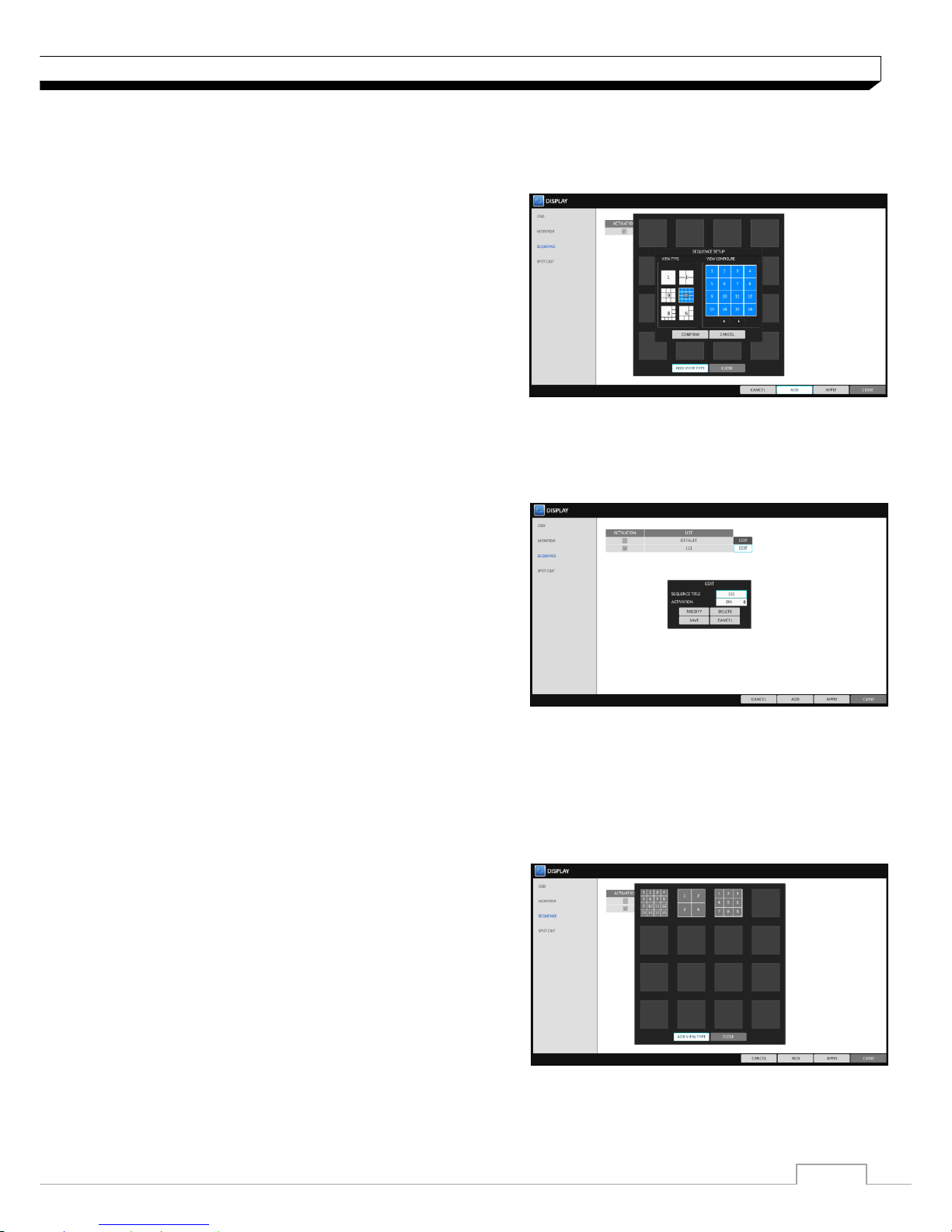
5. When the "SEQUENCE SETUP" dialog appears, select a split mode that you want
to add from <VIEW TYPE>.
6. If the selected split mode is displayed on <VIEW CONFIGURE>, select a channel you want
to display in each split screen.
7. Click <CONFIRM>.
The set sequence mode is confirmed and will be
added to the Add Sequence list in order
8. When done, click <CLOSE> in the bottom of the
screen.
After the sequence type is saved, you will return to
the previous screen.
9. Place your mouse cursor over desired tile of
added sequence, right Right-click on it or press the [ENTER] button on the remote control
to edit or delete it.
To edit a sequence
1. Select a sequence that you want to edit in the list.
2. The "EDIT" dialog appears.
3. Use the [▲▼◀▶/ENTER] buttons on the remote
control or use the mouse to edit the selected
sequence.
>SEQUENCE TITLE : enter a new sequence name.
>ACTIVATION : specify the use of the sequence.
>MODIFY : change the settings of the sequence
mode.
>DELETE : delete the selected sequence list.
>CANCEL : cancel the changes.
4. Pressing the <EDIT> button will display the Edit Sequence window.
5. To change the existing settings, select a screen mode that you want to edit and right-click to
display the context menu. Then, select <EDIT>.
6. When done, click <CLOSE> to close the window.
7. To apply your changes, click <APPLY>.
22
System Setting
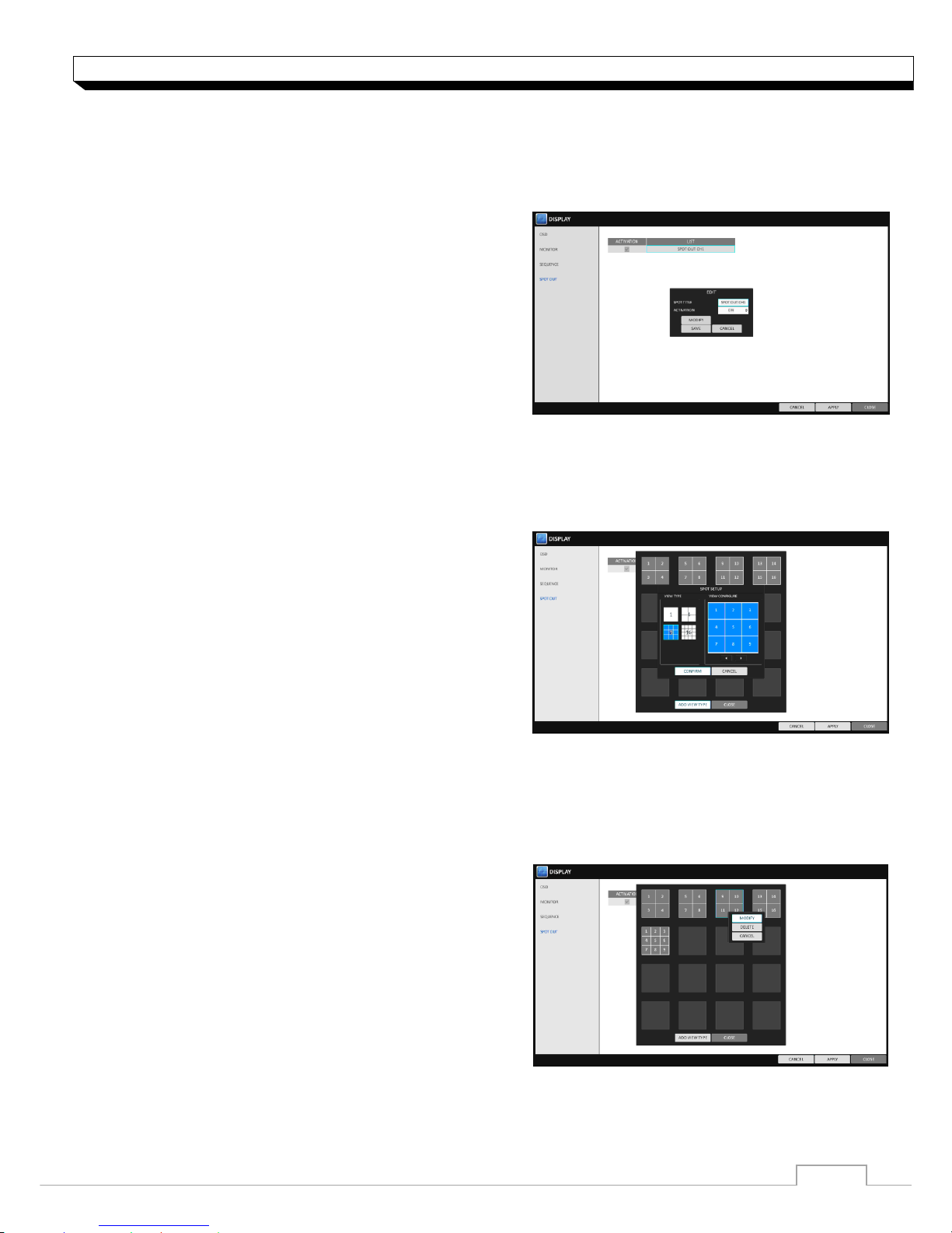
SPOT OUT (1U Model)
Apart from the main screen display, you can configure the Spot Out to display a Live channel as
needed in various live view types. You can set the live view type of display output through the
[SPOT] terminal and activate / deactivate it.
1. From <SYSTEM SETUP> - <DISPLAY>,
select <SPOT OUT>.
2. Use [▲▼◀▶/ENTER] button of the remote
control or mouse to edit Spot Out properties.
>SPOT TITLE : Name the Spot Out setup.
>ACTIVATION : Set whether to activate /
deactivate the spot out setup.
>MODIFY : Edit the view type of the spot output.
>SAVE : Save the changes of spot output settings.
3. To apply your changes, click <APPLY> button.
4. Once completed with setup, press [EXIT] button of the remote control or click <CLOSE> button
on the bottom of the screen. A confirmation dialog appears and returns to the previous menu.
To add a View Type to a SPOT OUT
1. Select an item from the SPOT OUT list to be changed.
2. The “EDIT” window appears, click <EDIT> button.
3. When the View Type selection window appears,
click <ADD VIEW TYPE> button.
4. Select the desired View Type and configuration,
and click <OK> button.
5. Complete adding and click <CLOSE> to close
the edit window.
9 and 16 split screen mode are available only for 16 channel model.
To edit or delete View type of the SPOT Out
1. Select an item from the SPOT OUT list to be changed.
2. The “EDIT” window appears, click <EDIT> button.
3. When the View Type selection window appears,
select the desired View Type to be edited or
deleted, and press [ENTER] button of the remote
control or right click on it.
> MODIFY : Displays “SPOT SETUP” window
for editing View Type and other properties.
> DELETE : Deletes the selected View Type.
5. Complete editing and click <CLOSE> to close the edit window.
23
System Setting
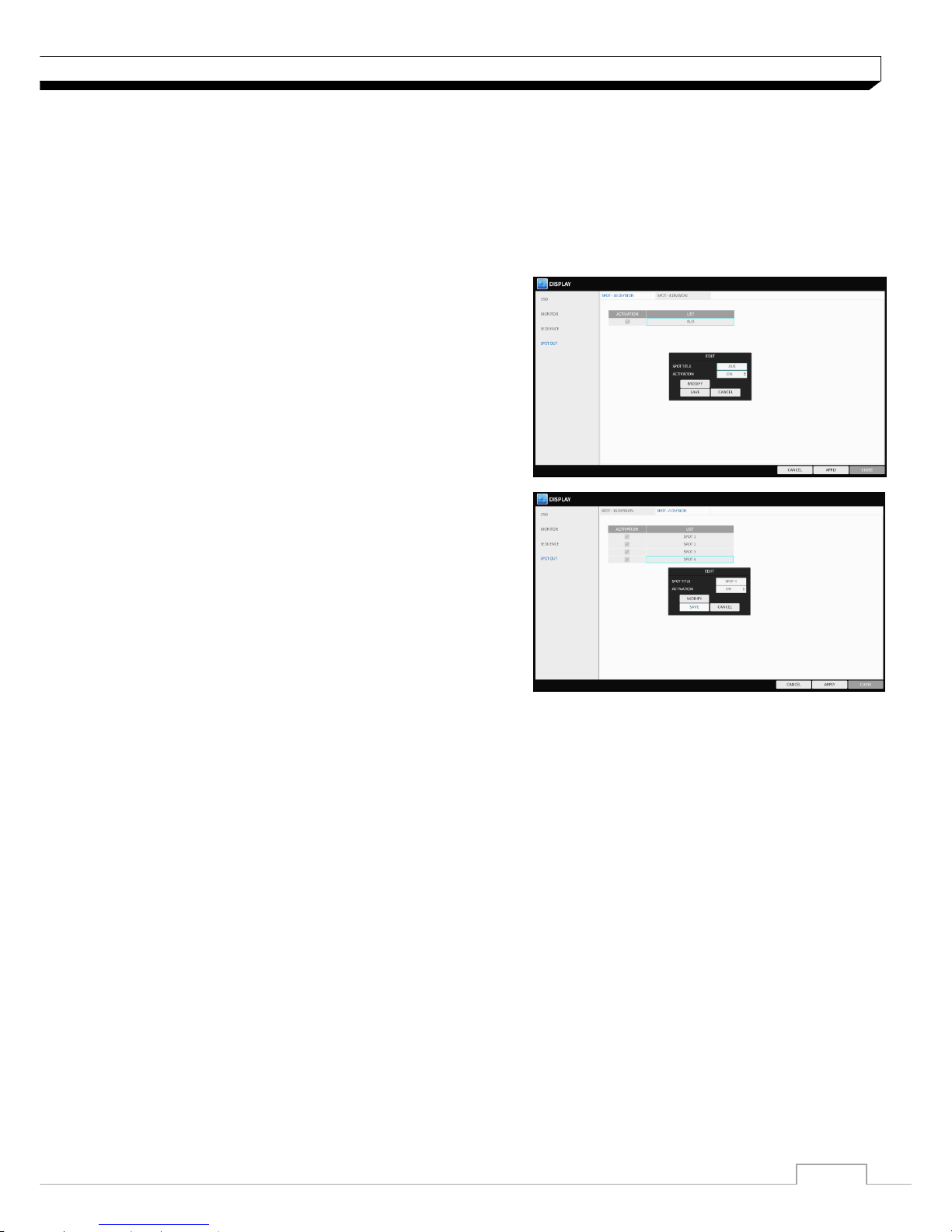
SPOT OUT (2U Model)
2U model has two types of SPOT output port.
AUX : Programmable. Support 1/4/9/16 display mode.
SPOT 1-4 : Programmable. Supports 1/4 display mode.
1. From <SYSTEM SETUP> - <DISPLAY>, select <SPOT -16DIVISION> or
<SPOT-4DIVISION>.
2. Setting menu is the same as 1U model on
previous page.
24
System Setting
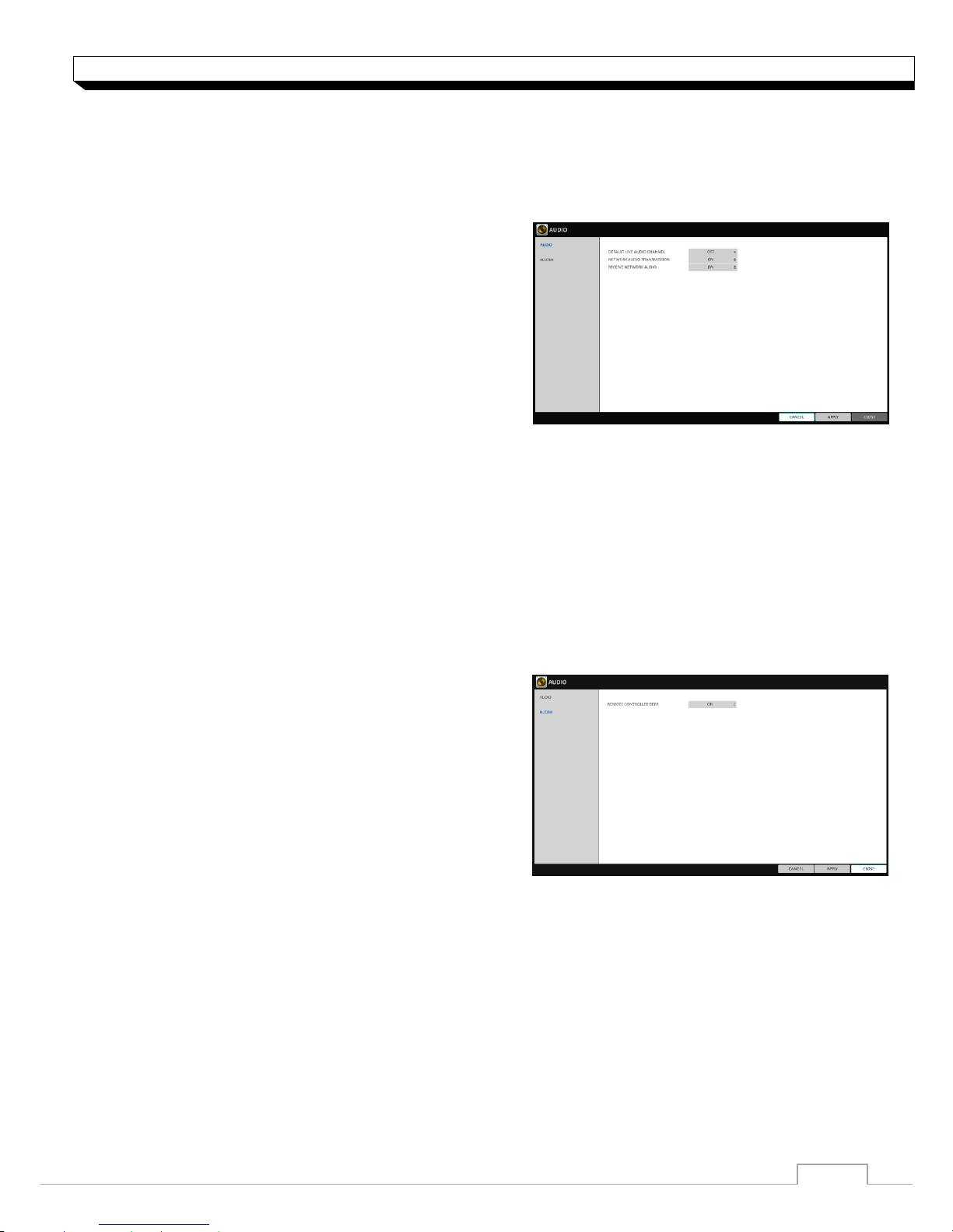
Audio Setup
Choose whether to receive the live sound source and select an audio channel.
1. From <SYSTEM SETUP> - <AUDIO>, select <AUDIO>.
2. Use the [▲▼◀▶/ENTER] buttons on the remote
control or use the mouse to select an item that
you want to edit.
>DEFAULT LIVE AUDIO CHANNEL : select an
Audio channel to monitor on the live screen.
>NETWORK AUDIO TRANSMISSION : decide if
DVR transfers the audio signal to the remote client.
DVR PC(Remote client)
>RECEIVE NETWORK AUDIO : decide if DVR
receives the audio signal from the remote client.
PC(Remote client) DVR
3. To apply the change, click <APPLY>button.
4. When done, press the [EXIT] button on the remote control or click <CLOSE> button.
The confirmation message appears and you will return to the previous menu.
Buzzer output
You can set to output the buzzer if you manipulate the remote control.
1. From <SYSTEM SETUP> - <AUDIO>, select
<BUZZER>.
2. Use the [▲▼◀▶/ENTER] buttons on the remote
control or use the mouse to select an item that you
want to edit.
> REMOTE CONTROL : specify the output of a beep
when you press a button on the remote control.
3. To apply the change, click <APPLY> button/
4. When done, press the [EXIT] button on the remote control or click <CLOSE> button.
The confirmation message appears and you will return to the previous menu.
25
System Setting
User Setting
You can configure the settings regarding user management and user and group permissions.
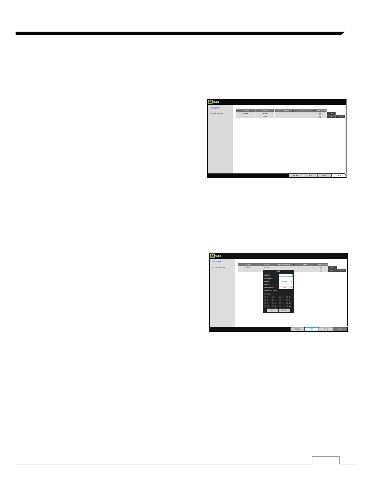
Management
You can add a user account(s) that can be edited at a later time.
1. From <SYSTEM SETUP> - <USER>, select
<MANAGEMENT>.
2. Use the [▲▼◀▶/ENTER] buttons on the remote
control or use the mouse to add a user account or
select an item that you want to edit.
3. To apply the change, click <APPLY> in the bottom
ofthe screen.
4. When done, press the [EXIT] button on the remote
control or click <CLOSE> in the lower screen.
The confirmation message appears and you will return to the previous menu.
To add a user account
1. Click <ADD> in the bottom of the screen.
2. Use the [▲▼◀▶] buttons on the remote control and
move to a desired item. Then, press [ENTER] to
select the item.
> USER ID : enter the user ID using the virtual
keyboard.
> PASSWORD : With the virtual keyboard, enter the
password.
> GROUP : From <ADMIN>, <MANAGER> and
<USER>, select a group that the user belongs to.
> EMAIL : Type in the e-mail address to which you will receive notification of an event if it occurs.
> EMAIL NOTIFY : Choose whether you will receive notification of an event if it occurs.
To use <EMAIL NOTIFY>, a send mail server and its port should be configured previously.
> COVERT CHANNEL : You can set the channel to hide from a specific user.
< COVERT CHANNEL >, option hides the video of the selected channel from being
displayed on the screen.
3. When done, click <OK>. The added user account will be listed.
26
System Setting
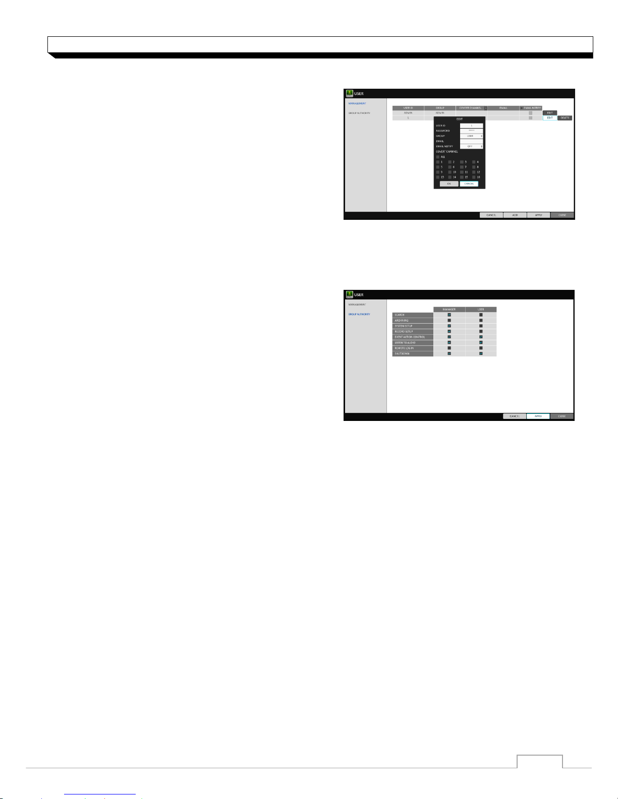
To edit the user account information
1. From the list of users, select a user account to edit
and click <EDIT> next to it.
2. From the Edit window, make necessary changes
and click <OK>.
3. To delete the user account, click <DELETE>.
The <ADMIN> account cannot be changed
or edited
Group Authority
You can grant different user groups different permissions to a specific menu.
1. From <SYSTEM SETUP> - <USER>, select <GROUP AUTHORITY>.
2. Use the [▲▼◀▶/ENTER] buttons or use the
mouse to set the permissions for both
<MANAGER>and <USER> groups.
>SEARCH : Set the permissions for the Search menu.
>ARCHIVING : Set the permissions for the Backup
menu.
>SYSTEM SETUP : Set the permissions for the
System Setup menu.
>RECORD SETUP : Set the Access Permissions for the Record Setup menu.
>EVENT ACTION CONTROL : Set the permissions to output the alarm or control the buzzer if an
event such as alarm occurs.
>LISTEN TO AUDIO : Set the permission to listen to the audio.
>REMOTE LOG IN : Set the permission to access remotely.
>SHUTDOWN : Set the permission to shut down DVR from the System menu.
The <ADMIN> account is the master account allowed for all permissions, which is not edited
for individual permissions.
3. To apply the change, click <APPLY> in the bottom of the screen.
4. When done, press the [EXIT] button on the remote control or click <CLOSE> button.
The confirmation message appears and you will return to the previous menu.
27
System Setting
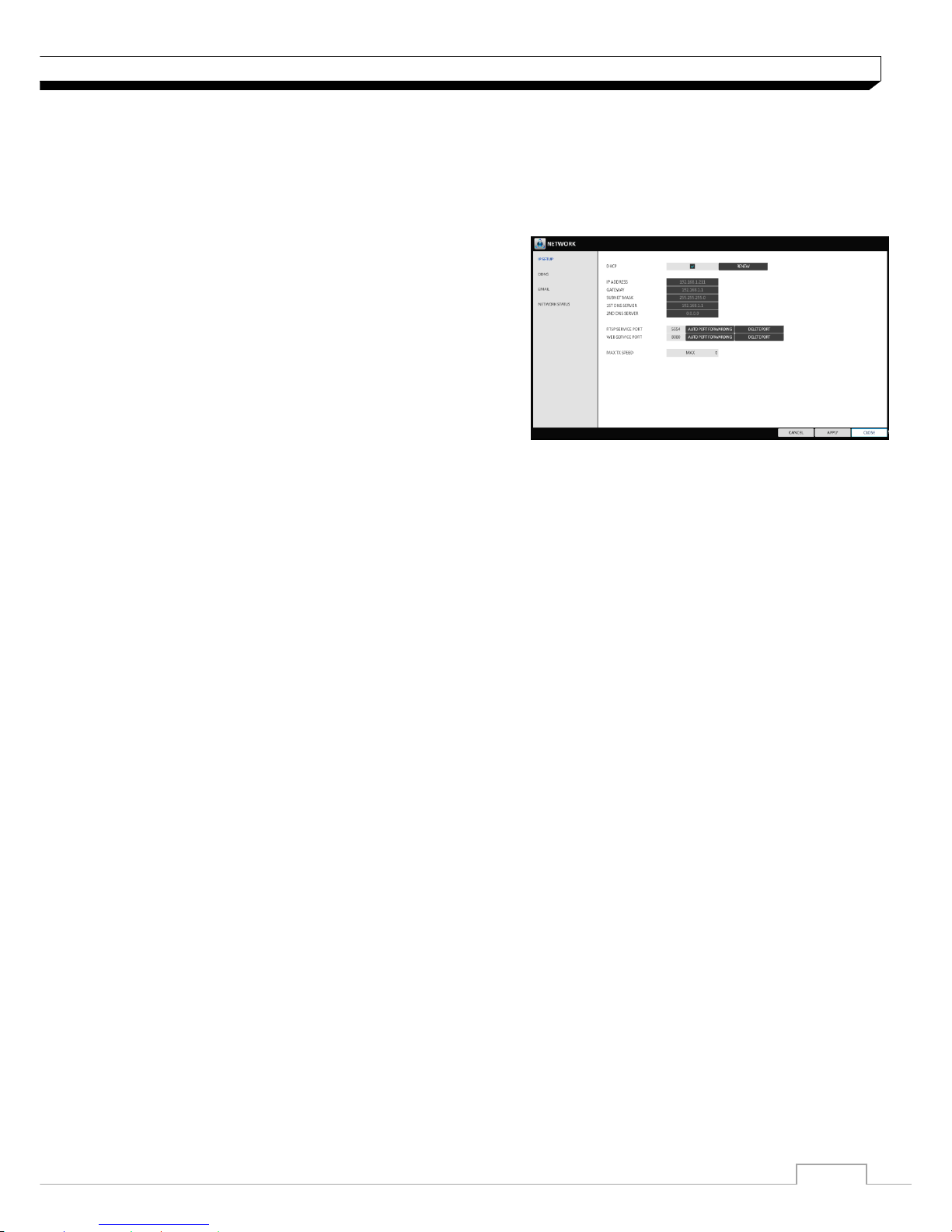
Network Setup
You can set IP address, DDNS and E-mail settings, and check network status.
IP Setup
Specify the IP address as well as the remote service port.
1. From <SYSTEM SETUP> - <NETWORK>,
select <IP SETUP>.
2. Use the [▲▼◀▶/ENTER] buttons on the remote
control or use the mouse to specify each item of the
network settings.
>DHCP : If it is checked, set the IP address of the
DVR to Dynamic IP.
For DHCP address allocation, the DVR should be
connected to a network environment such as router that provides with DHCP server.
3. Deselect DHCP option to enable manual static address configuration. service.
>IP ADDRESS : Provide the IP address.
>GATEWAY : provide the gateway address.
>SUBNET MASK : provide the subnet mask address.
>1ST DNS SERVER : Enter the address of the primary DNS server.
>2ST DNS SERVER : Enter the address of the primary DNS server.
>RTSP SERVICE PORT : port number that the remote client receives the DVR video from.
>WEB SERVER PORT : port number used for connecting to the DVR with the web browser.
>PORT FORWARDING : If you are using a router, you can set the port forwarding so that external
access to the DVR is enabled.
If the router does not support the uPnP protocol, you must set the port forwarding manually.
For more information, contact your network administrator.
>DELETE PORT : release the port forwarding settings for the router.
>MAX TX SPEED : Limit the network transfer rate to access a remote client.
The video signal may be transferred at a less rate than specified, which depends on the status of
your network connection.
4. To apply the change, click <APPLY> button.
5. When done, press the [EXIT] button on the remote control or click <CLOSE> button.
The confirmation message appears and you will return to the previous menu.
28
System Setting
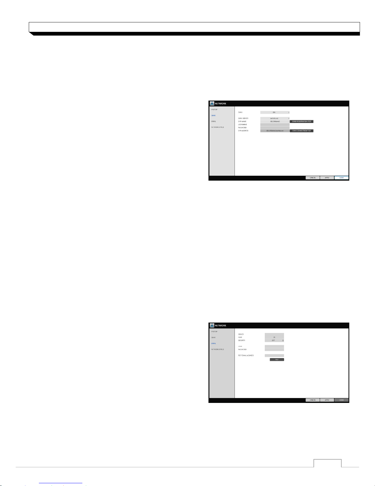
DDNS
You can configure the DDNS settings so that remote users who are connected to the network can
access remotely.
DDNS is an IP redirection service in a dynamic IP environment that redirects (maps) the new
IP address to a registered domain name each time the IP address is changed.
1. From <SYSTEM SETUP> - <Network>, select
<DDNS>.
2. Use the [▲▼◀▶/ENTER] buttons on the remote
control or use the mouse to specify the use of DDNS
and select a server.
>DDNS : Specify the use of DDNS connection.
>DDNS SERVER : Select a server to connect to.
>DVR NAME : Enter the name of the DVR that you
want to use as DDNS.
>DDNS REGISTRATION TEST : Check if the <DVR NAME> can be set as DDNS. If there is a
duplicate name in the server, the registration will fail. If this is the case, rename the
<DVR NAME> and press Test to check if it works properly.
>DVR ADDRESS : Provide the <DVR NAME> and press the <DDNS REGISTRATION
TEST> button. The name will be added automatically.
>DDNS CONNECTION TEST : Perform the connection test to check if DDNS is normally
registered.
3. To apply the change, click <APPLY> in the bottom of the screen.
4. When done, press the [EXIT] button on the remote control or click <CLOSE> in the lower
screen. The confirmation message appears and you will return to the previous menu.
Email
You can register and test an email address so that an email notification is delivered at a specific
interval or if an event occurs.
1. From <SYSTEM SETUP> - <NETWORK>,
select <EMAIL>.
2. Use the [▲▼◀▶/ENTER] buttons on the remote
control or use the mouse to specify the use of email
and select a server.
>SERVER : Set up the mail server. Set the mail
Server that will be used for notification to the DVR.
>PORT : Enter the mail server port.
>SECURITY : If it is set to <On>, the email will be transferred in secure mode.
If it is set to <Off>, the email will be transferred to a server that does not support SSL.
>USER : Provide the email account (ID) of the sender.
29
System Setting
>PASSWORD : Provide the password of the sender.
>TEST EMAIL ADDRESS : Enter an email address for the test purpose.
>TEST : Send a test email and check if the test email is delivered normally.
3. To apply the change, click <APPLY> in the bottom of the screen.
4. When done, press the [EXIT] button on the remote control or click <CLOSE> in the lower
screen. The confirmation message appears and you will return to the previous menu.
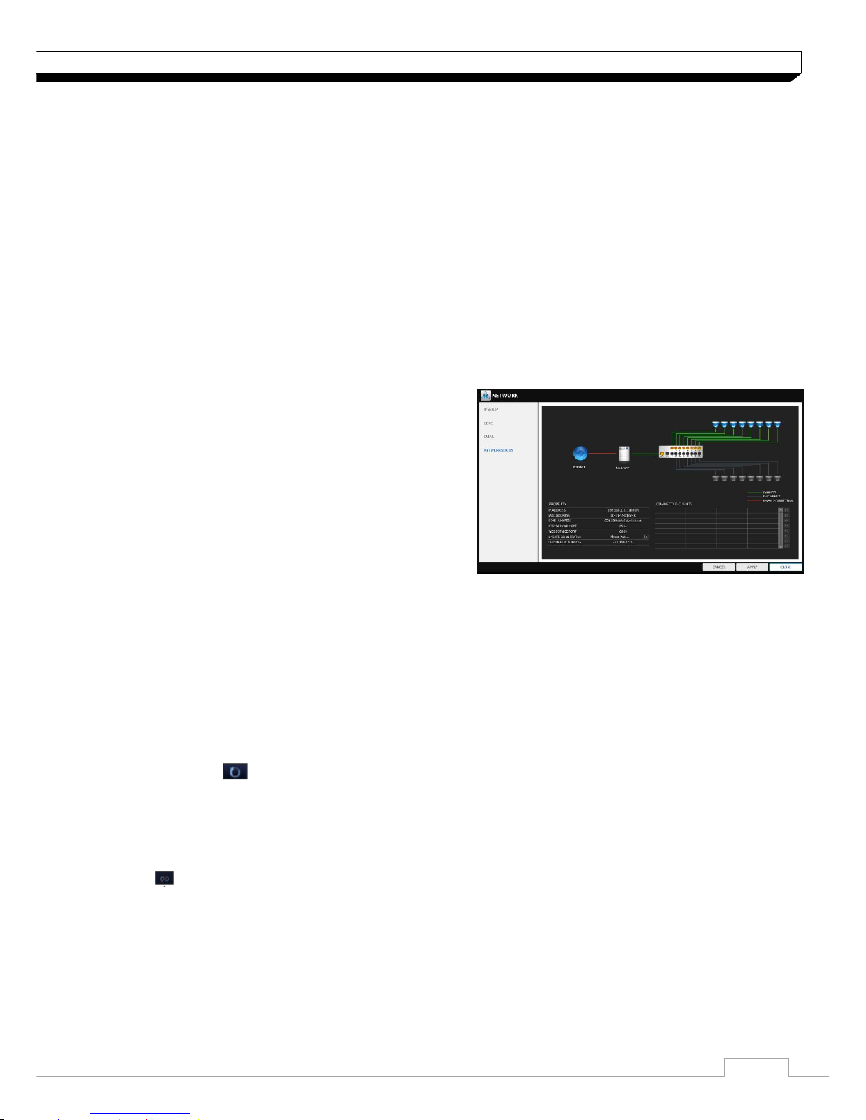
Network Status
From the network map screen, you can check the internet connection status and camera connection
status, and Check also the details of the connection status for each camera.
1. From <SYSTEM SETUP> - <NETWORK>, select <NETWORK STATUS>.
2. When done, press the [EXIT] button on the
remote control or click <CLOSE> button.
The confirmation message appears and you will
return to the previous menu.
Network status
> IP ADDRRESS : Indicates the internal IP address
of the DVR.
> MAC ADDRESS: Indicates the internal MAC
address of the DVR.
>DDNS ADDRESS: Indicates the internal DDNS address of the DVR.
>RTSP SERVICE PORT : Indicates the network port of the video service.
For remote service, the router must have set up the port forwarding.
>WEB SERVICE PORT : Indicates the web service network port.
For the remote service to be enabled, the corresponding port of the router should have set
up the port forwarding.
>DDNS UPDATE STATUS : Shows if the DDNS address was registered to the DDNS server
normally. Press < > to try to register the DDNS address forcibly.
>EXTERNAL IP ADDRESS : Indicate the IP address for the internet, accessible from the DVR.
The DVR can be granted access with the web browser at http://<External IP Address>:<Web
Service Port>. The IP address can vary in a dynamic IP environment.
>CONNECTED CLIENTS :Shows the list of clients that are currently connected.
Press < > to terminate the connection of an unwanted client forcibly.
Termination is limited to only users in a lower group than the current user.
30
System Setting
System Setting
You can configure the settings of date/time, system management, and keyboard controller.
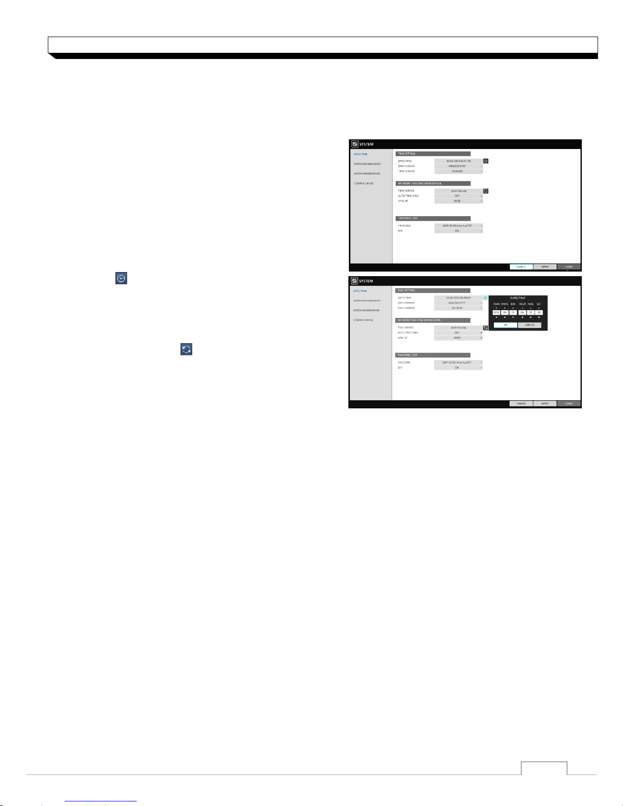
Date/Time
Specify the current date and time.
1. From <SYSTEM SETUP> - <SYSTEM>, select
<DATE/TIME>.
2. Use the [▲▼◀▶/ENTER] buttons on the remote
control or use the mouse to change the time or set
the options as necessary.
>DATE/TIME : Set the current time and date.
Click< > to adjust the time manually.
>DATE FORMAT : specify the date format.
>TIME FORMAT : specify the time format.
>TIME SERVER : obtain the current time from the
time server. Click < > to get the current time.
>AUTO TIME SYNC : automatically synchronize the
time with the time server at a specific time.
>SYNC AT : Set the time to sync with the time server.
>TIMEZONE : specify the GMT standard time for your local area.
>DST : You can set up or release the DST (Daylight Saving Time).
Both <TIME SERVER> and <AUTO TIME SYNC> will be enabled only if the DVR is
connected to the Internet.
3. To apply the change, click <APPLY> in the bottom of the screen.
4. When done, press the [EXIT] button on the remote control or click <CLOSE> in the lower
screen. The confirmation message appears and you will return to the previous menu.
 Loading...