

Gambro Prismaflex User training
Prismaflex Machine

Prismaflex Schematic
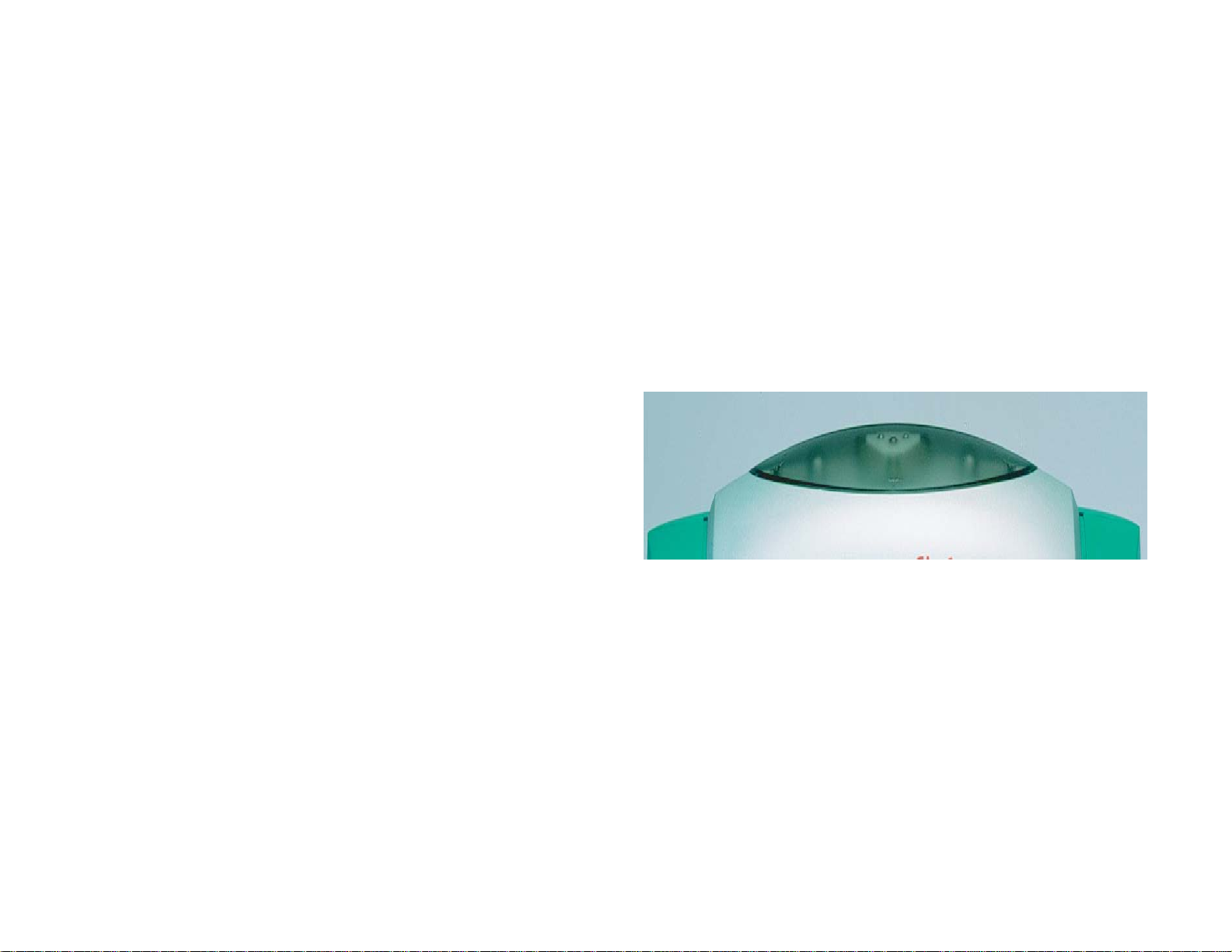
Communication Unit
• Give a general indication of
operating conditions.
• Status Lights
– Green Indicates all parameters
are normal during treatment
–YellowIndicates advisory or
caution alarm
–RedIndicates highest priority
alarm and needs immediate
intervention.
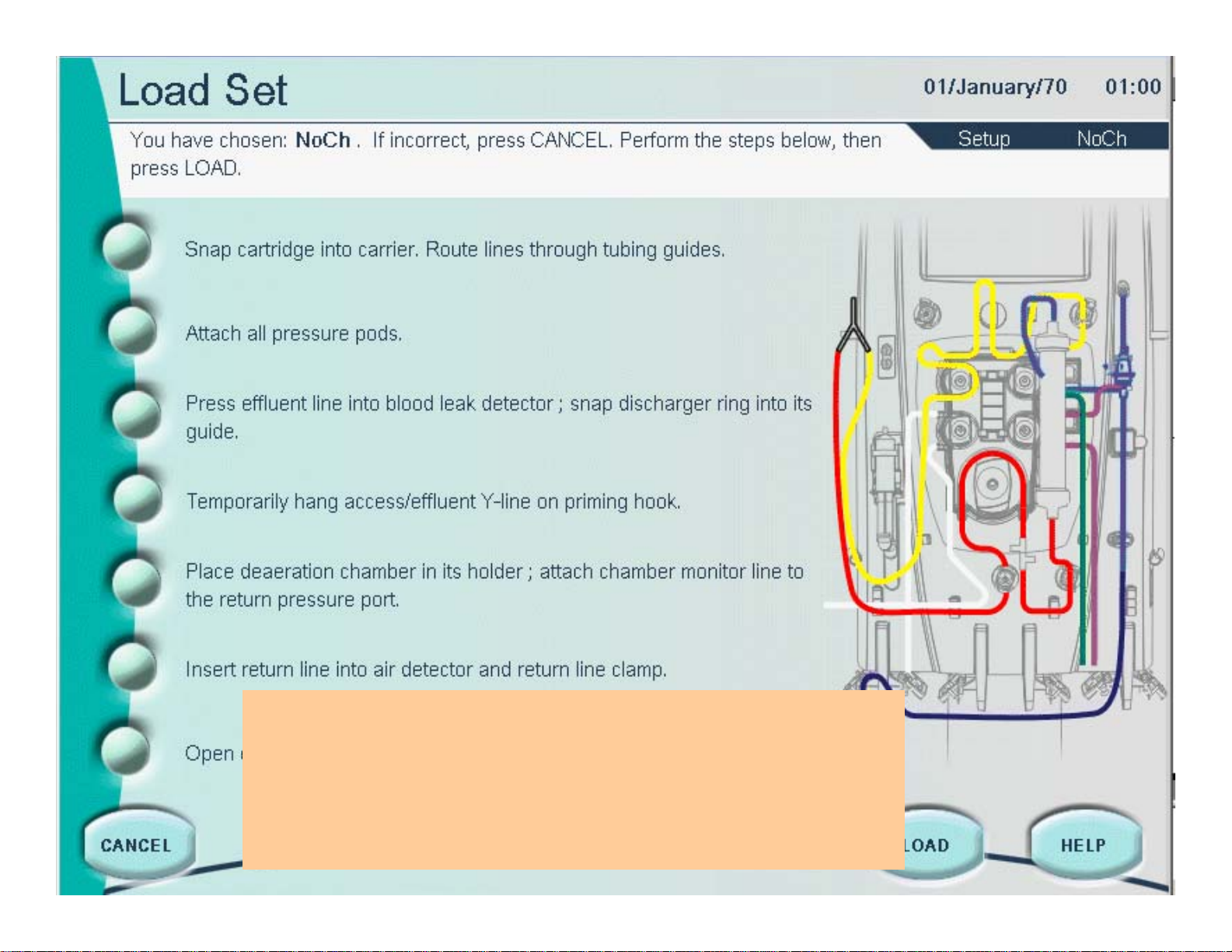
Interactive display is your command center.
It provides screens to guide you through the
functionalities of the machine. The contents of the
display depend on the software mode and
operations at the moment.
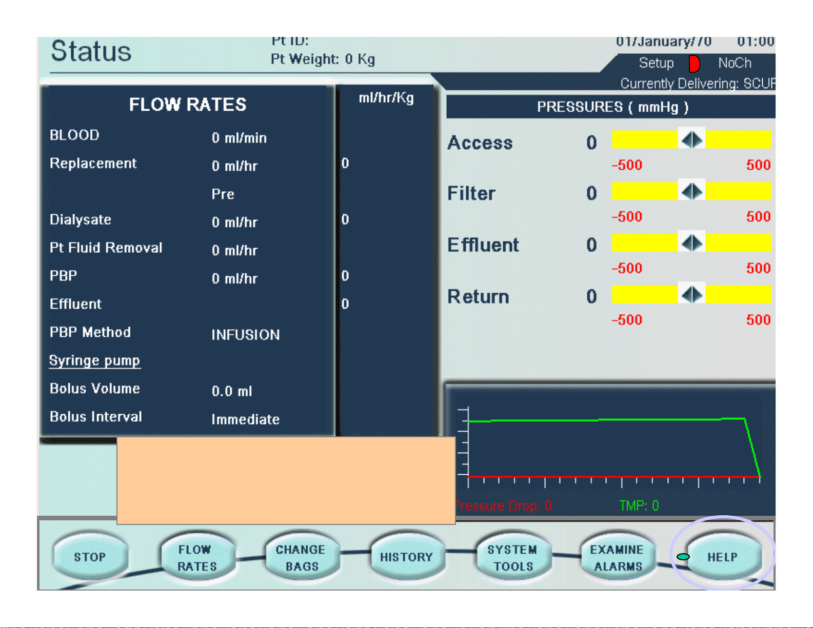
The status screen is the main operating
screen while a treatment is underway. You
can see pressure conditions in the set and
the flow rate settings at a glance.

Flow Control Unit
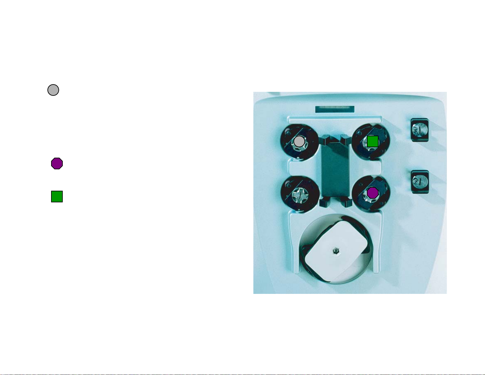
Control Unit
Effluent pump: Pumps ultrafiltrate/dialysate.
Automatically controls the ultrafiltration rate
in the filter, based on the current patient fluid
removal, pre-blood pump, replacement and
dialysate pump rates. Max flow: 10,000ml/hr
Pumps replacement solution into the blood
flowpath. Max flow: 8000ml/hr
Pumps dialysate into the fluid compartment of
the filter. Max flow:
8000ml/hr.
Pinch Valves:
Mechanisms that hold the pinch valve
segments of the Prismaflex Set. The valves
open/close automatically and allow pre and
post filter options for infusing replacement
solution.
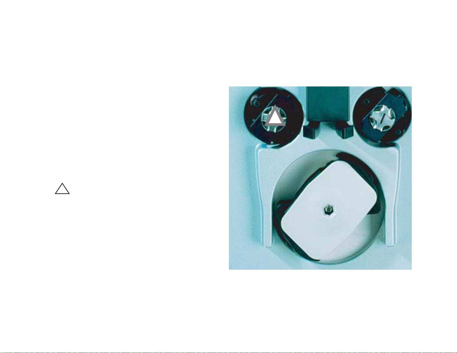
Flow Control Unit
Blood pump
Occlusive, peristaltic pump that conveys
blood through the blood flowpath of the
set and back to the patient. Blood
source may be directly from patient, or
from a device, such as an ECMO
machine. Flow rate up to 450ml/min.
Pre-blood pump (PBP)
Can be used to deliver a sterile infusion
solution into the blood access line
before the blood pump. May be used for
anticoagulation strategies or for predilution. Max flow rate: 8000ml/hr.
Prismaflex does not allow the PBP rate
to exceed the blood flow rate.
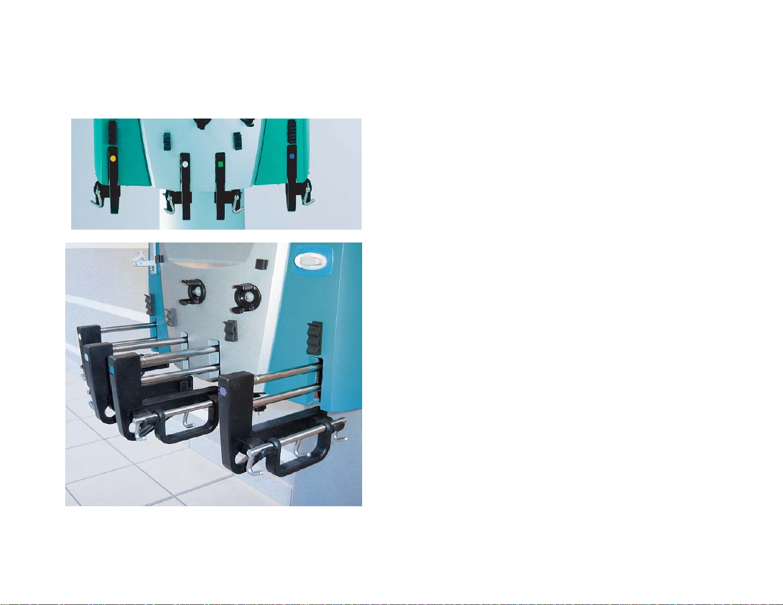
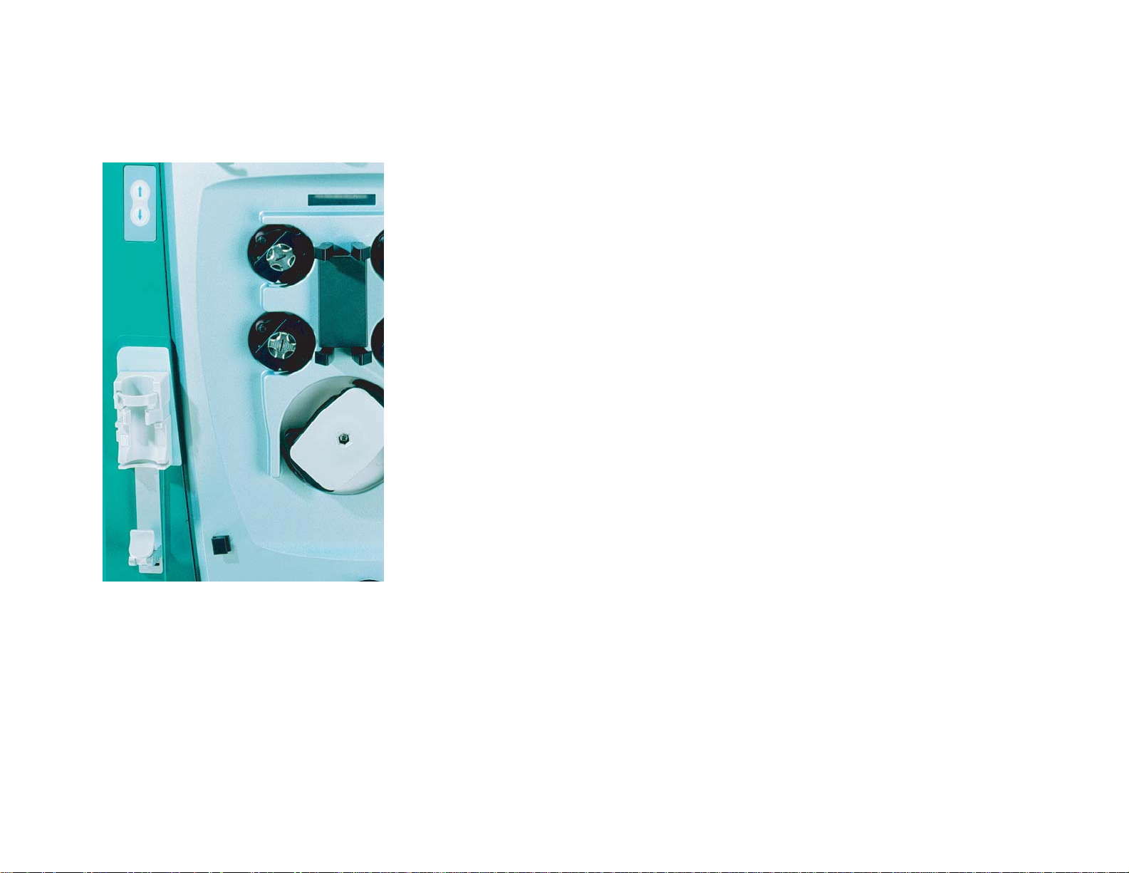
Control Unit
Scale hook assembly
Slide-out bar tray and removable
carrying bar for hanging/removing
fluid bags. Rotate the handle of the
carrying bar downwards, then push
the bar tray into the scale to close it.
Scales
Effluent
Pre-blood pump (PBP)
Dialysate
Replacement
Precision scales independently
monitor the weight of each bag and
control ultrafiltration and patient fluid
removal.
Tubing guides
Secure the lines of the set in position
on the control unit. The guide color
matches the color of the set line it
holds.
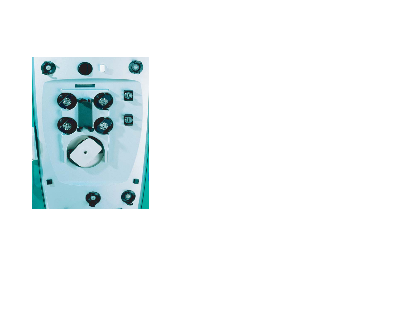
Flow Control
Pressure sensor housing
Access
Filter
Effluent
Unused (for future therapies)
Each pressure sensor housing holds the
corresponding pressure pod of the Prismaflex
Set and provides a connection between the pod
and an internal pressure sensor. This provides
non-invasive pressure monitoring of the access
line, filter, and effluent line. There are no airblood interfaces.
Control Unit
Syringe pump assembly
Delivers anticoagulant or other solution into the blood
flowpath via a syringe. Delivery can be continuous or
in boluses (See Prismaflex Operator Manual for
specification).
Syringe pump control panel
UP and DOWN buttons on the machine allow you to
install or remove a syringe.
Bar code reader
Each type of Prismaflex Set has its own range of
alarm limits and flow rate possibilities. When a set is
loaded, the bar code reader automatically scans the
identification code. The control unit then accesses the
correct operating ranges and priming sequence. This
is an important, proactive safety feature.
Control Unit
Cartridge carrier
Houses the cartridge of the
Prismaflex Set and moves inward
to automatically load the set into
the pumps raceways.
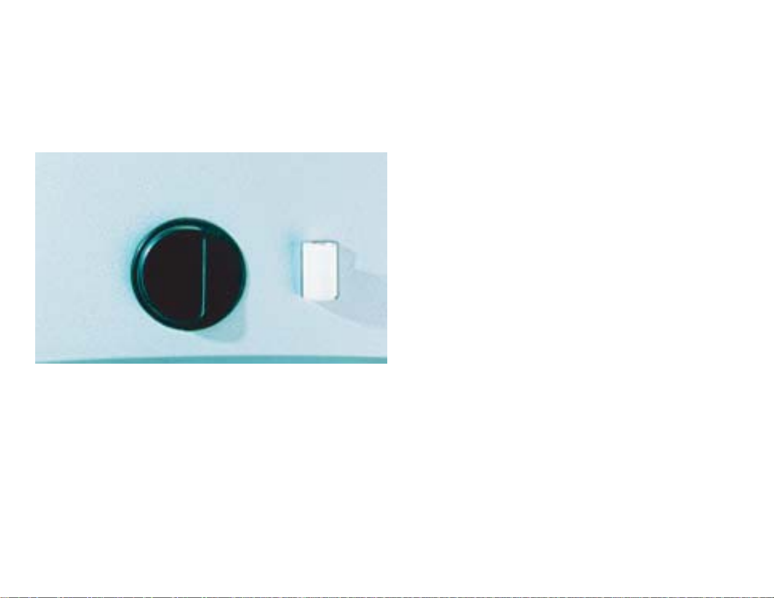
Blood leak detector (BLD)
Continuously monitors the effluent
line for the presence of red blood
cells.
Discharger ring guide
Holds the discharger ring, located
on the effluent line of the
Prismaflex Set. Provides an
electrical ground and minimizes
electrical interference with other
ICU devices.
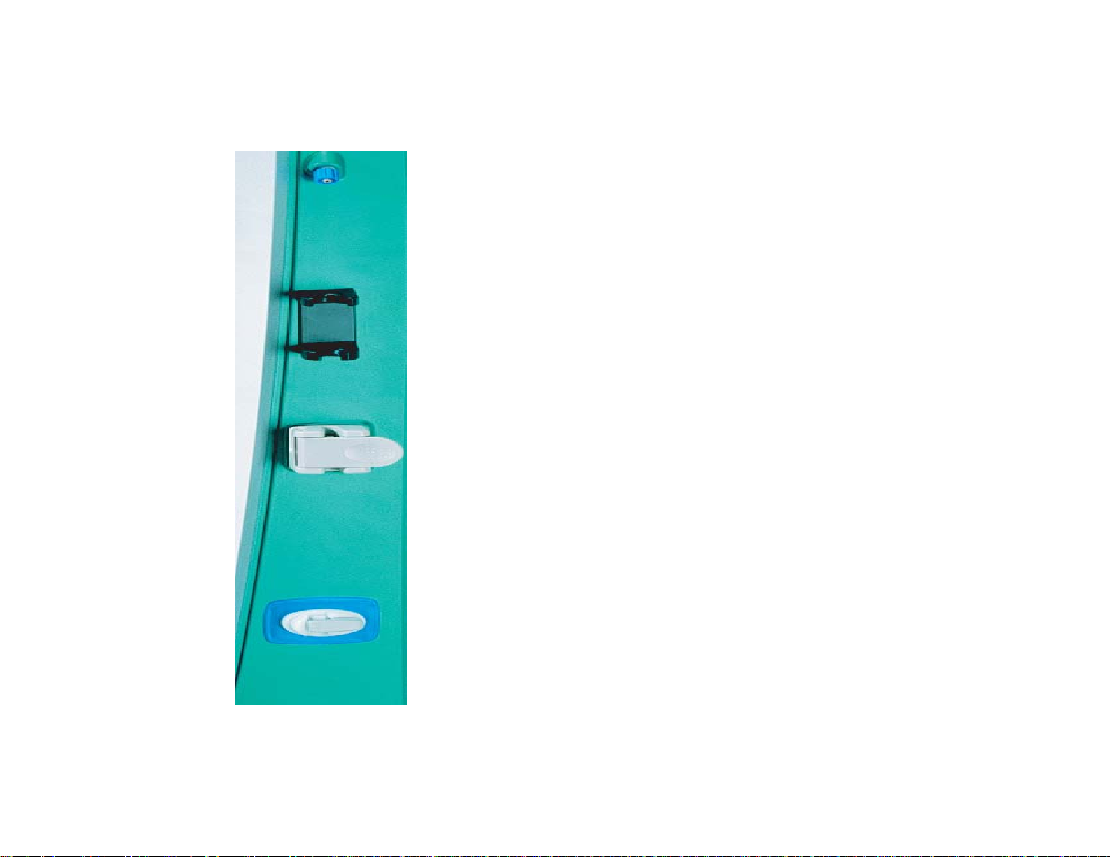
Control Unit
Return pressure port
Provides a connection between an internal pressure
sensor and the monitor line of the set’s deaeration
chamber. Non-invasive pressure monitoring of the
deaeration chamber and return line is provided. A
fluid barrier in the monitor line protects the interior
of the control unit form accidental fluid entry.
Deaeration chamber holder
Secures the deaeration chamber, which is located
on the return line of the Prismaflex Set.
Ultrasonic air bubble detector (UABD)
Continuously monitors the return line for air
bubbles. Within the housing are also a tubing
detection switch and a blood sensor. These sensors
provide additional monitoring of return line
conditions while you are setting up for treatment.
Return line clamp
This occlusive safety clamp closes if any condition
of possible patient hazard is detected. The clamp
prevents blood and/or air from passing to the
patient. A tubing detection switch is also in the
clamp housing, allowing Prismaflex to notify you if
the return line is not correctly installed in the clamp.
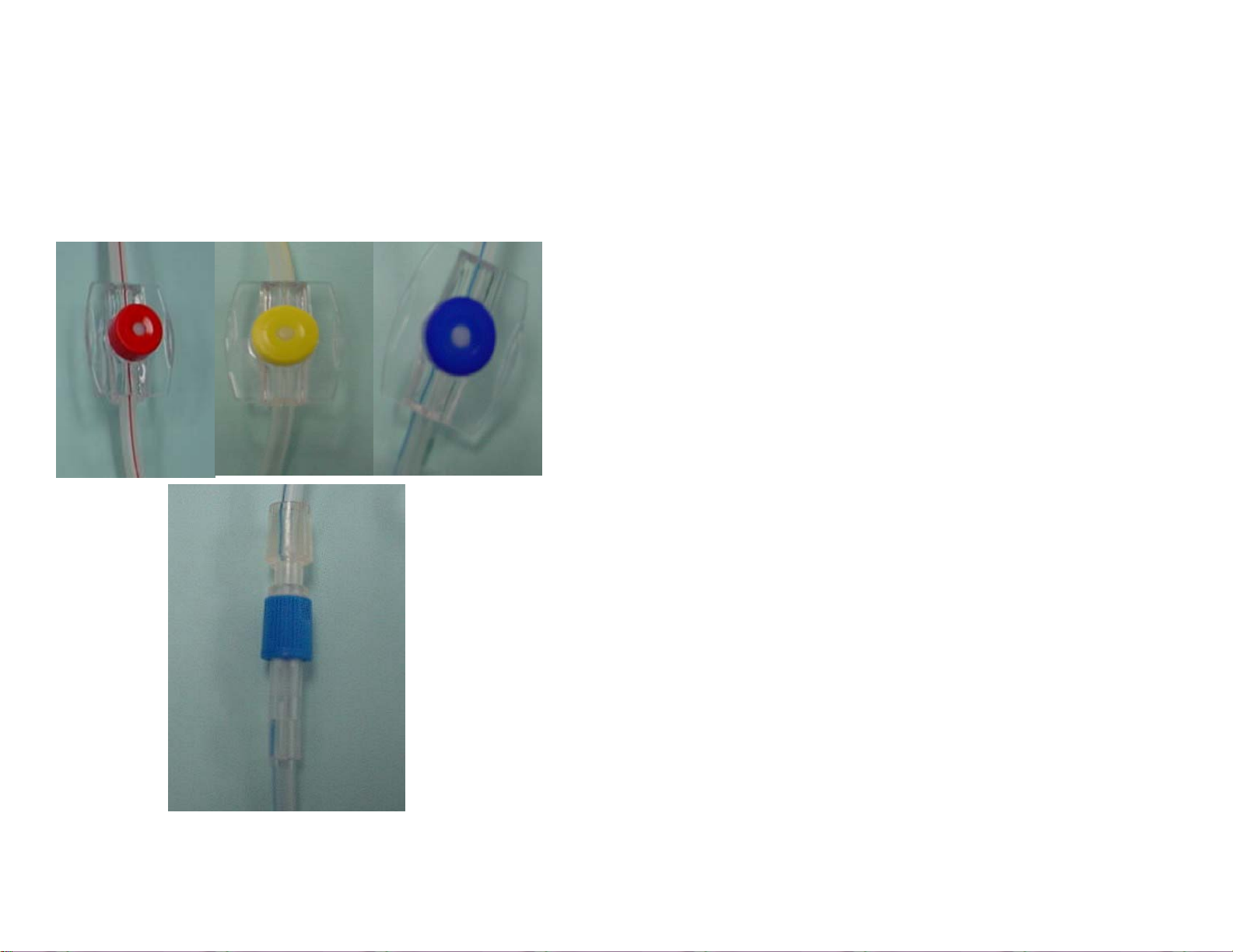
Sets, Therapies and Bags
SAMPLE SITES
•Effluent line
•Access line before the blood pump
•Access line (filter) after the blood pump
•Return line before the blood warmer
connectors and deaeration chamber.
Sample sites are color-coded ports with a
latex free plug that allows needle entry. You
can use these to obtain fluid or blood
samples, or to remove trapped air.
BLOOD WARMER CONNECTOR
This luer-lock connector allows you to attach a
disposable set for a blood warmer. The
connection is made to the return line before
the deaeration chamber. The warmer set must
be connected during Setup procedures—it is
automatically primed along with the
Prismaflex Set.
Sets, Therapies and Bags
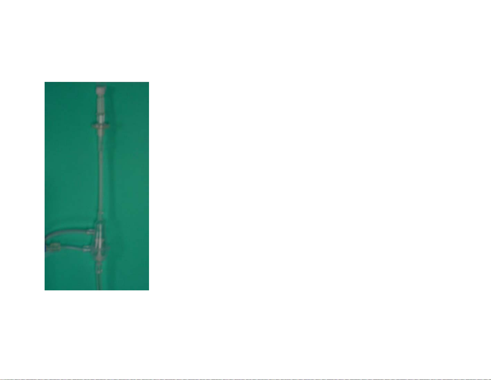
DEAERATION CHAMBER
Manages air
Bottom to tope blood flow in the set promotes continuous
elimination of air. In the return line, the dearation chamber provides
a unique conveyance path that works like a vortex to propel all air
out of the blood. Post-filter replacement solution is added into the
deaeration chamber on top of the blood. Using a minimum of 200
to 500 ml/hr of post filter replacement will prevent air/blood
interface. This is recommended to minimize clotting and foaming
into deaeration chamber.
Semi-automated fluid level adjustment
Arrow keys on a special screen allow you to easily adjust the fluid
level up or down in the chamber.
DEAERATION CHAMBER MONITOR LINE
Connects the deaeration chamber to an internal pressure sensor,
enabling return pressure monitoring and removal of air from the
chamber, if needed. A fluid barrier at the end of the line protects the
interior of the control unit form accidental blood/fluid entry.
Tightening the connections is part of your usual setup and
treatment management duties.
Sets, Therapies and Bags
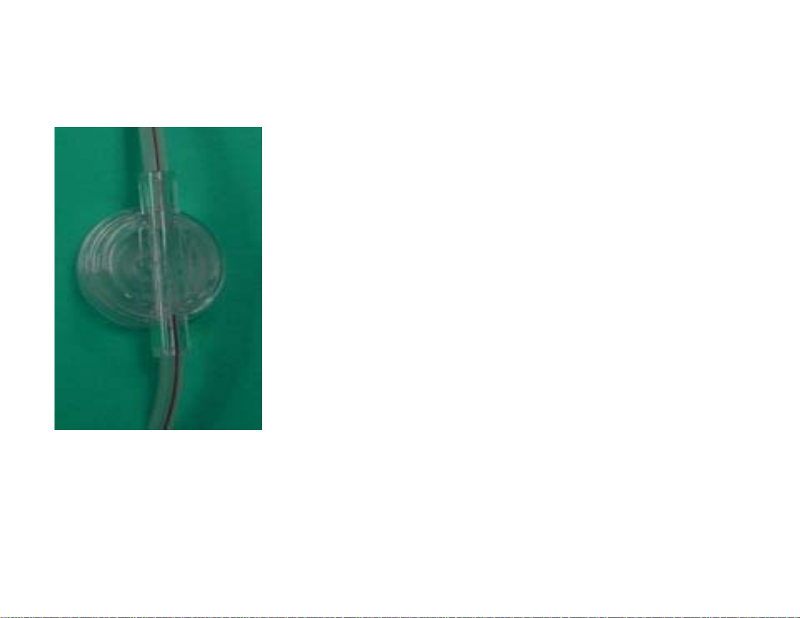
PRESSURE PODS
Effluent
Access
Filter
These integral pressure monitoring
components connect with pressure
sensors inside the machine. A
diaphragm in the pod moves according
to the pressure exerted by the fluid
flowing in the line. The internal pressure
sensor converts this motion to a
pressure reading…
When treatment begins, access pressure
is sensed to establish the type of blood
source (negative or positive pressure).
Software then activates the correct
access pressure monitoring range.
Sets, Therapies and Bags
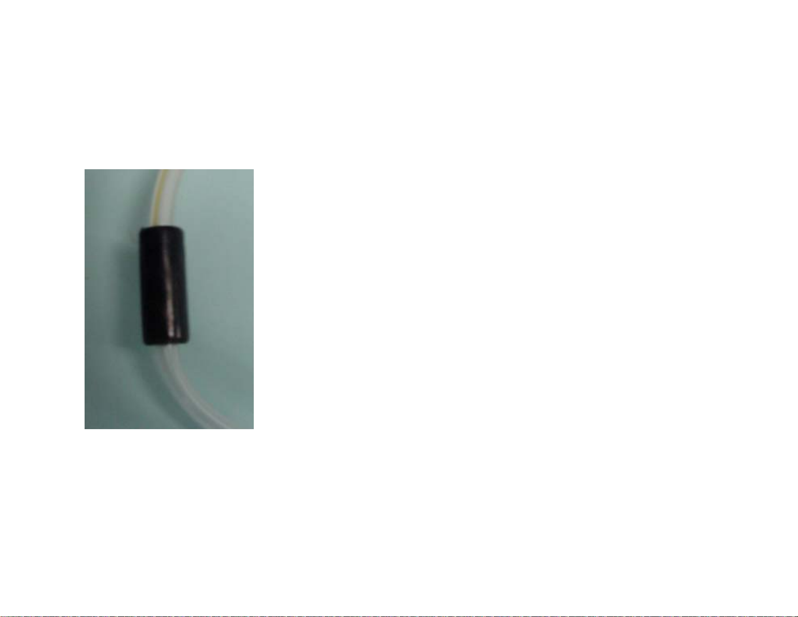
Discharger ring
This component on the effluent line
installs in the ring guide on the control
unit. Provides an electrical ground and
minimizes electrical interference with other
ICU devices.
Spike/Luer lock connector
Located at the tip of each solution line,
you may use either the spike or the luer
lock to connect to the fluid bags. If you’re
using the luer lock, you need to remove
the spike.
 Loading...