


Prismaflex®
Service Manual
For use with software version 7.xx
Manufacturer:
Gambro Lundia AB
Box 10101, Magistratsvägen 16, SE-220 10 Lund, Sweden
Tel: +46-46-16 90 00, Fax: +46-46-16 96 96
www.gambro.com
Questions or comments about this publication can be directed to your local representative or to the manufacturer.
Order number:
G5005209
Copyright:
© 2005–2012 Gambro Lundia AB
Gambro, Prismaflex, Adsorba, Prismaflo, Prismacomfort, Prismatherm, MARSFLUX, diaFLUX, diaMARS, X-MARS, septeX, oXiris, Hospal and MARS are trademarks belonging to the Gambro Group.
G5005209
Program version 7.xx

This page is intentionally left blank
G5005209 Program version 7.xx

Prismaflex® Service Manual
1.Before you get started
2.Installation Guide
3.Technical Description
4.Function Check
5.Alarms and Troubleshooting
6.Maintenance
7.Schematics
8.Specifications
9.Equations
G5005209
Program version 7.xx

Contents
1. Before you get started |
|
|
|
About this Manual . . . . . . . . . . . . . . . . . . . . . . . . . . . . . . . . . . . . . . . . . . . . . . . |
1:2 |
|
Keywords Used in this Manual . . . . . . . . . . . . . . . . . . . . . . . . . . . . . . . . . . . . . |
1:2 |
|
Complaint . . . . . . . . . . . . . . . . . . . . . . . . . . . . . . . . . . . . . . . . . . . . . . . . . . . . . |
1:3 |
|
Responsibility and Disclaimer . . . . . . . . . . . . . . . . . . . . . . . . . . . . . . . . . . . . . . |
1:3 |
|
Safety Definitions . . . . . . . . . . . . . . . . . . . . . . . . . . . . . . . . . . . . . . . . . . . . . . . |
1:4 |
|
Maintenance . . . . . . . . . . . . . . . . . . . . . . . . . . . . . . . . . . . . . . . . . . . . . . . . . . . |
1:5 |
|
Competence of Service Engineers . . . . . . . . . . . . . . . . . . . . . . . . . . . . . . . . . . . |
1:5 |
|
Technical Support . . . . . . . . . . . . . . . . . . . . . . . . . . . . . . . . . . . . . . . . . . . . . . . |
1:5 |
|
Symbols . . . . . . . . . . . . . . . . . . . . . . . . . . . . . . . . . . . . . . . . . . . . . . . . . . . . . . |
1:6 |
|
Electrical Safety . . . . . . . . . . . . . . . . . . . . . . . . . . . . . . . . . . . . . . . . . . . . . . |
1:6 |
|
Instructions and warnings . . . . . . . . . . . . . . . . . . . . . . . . . . . . . . . . . . . . . . . |
1:6 |
|
Information . . . . . . . . . . . . . . . . . . . . . . . . . . . . . . . . . . . . . . . . . . . . . . . . . |
1:7 |
|
Communication . . . . . . . . . . . . . . . . . . . . . . . . . . . . . . . . . . . . . . . . . . . . . . |
1:8 |
|
Environmental . . . . . . . . . . . . . . . . . . . . . . . . . . . . . . . . . . . . . . . . . . . . . . . |
1:8 |
|
Transportation and storage . . . . . . . . . . . . . . . . . . . . . . . . . . . . . . . . . . . . . . |
1:8 |
|
Solutions . . . . . . . . . . . . . . . . . . . . . . . . . . . . . . . . . . . . . . . . . . . . . . . . . . . |
1:9 |
|
Certification Marks . . . . . . . . . . . . . . . . . . . . . . . . . . . . . . . . . . . . . . . . . . . . |
1:10 |
|
Disposal . . . . . . . . . . . . . . . . . . . . . . . . . . . . . . . . . . . . . . . . . . . . . . . . . . . . . . |
1:10 |
|
Disposal of Discarded Equipment . . . . . . . . . . . . . . . . . . . . . . . . . . . . . . . . . |
1:10 |
2. |
Installation Guide |
|
About this Chapter . . . . . . . . . . . . . . . . . . . . . . . . . . . . . . . . . . . . . . . . . . . . . . . . . |
2:2 |
|
Installation . . . . . . . . . . . . . . . . . . . . . . . . . . . . . . . . . . . . . . . . . . . . . . . . . . . . . . . |
2:3 |
|
|
Contents of Prismaflex® Control Unit Shipping Carton . . . . . . . . . . . . . . . . . . . |
2:3 |
|
Electrical Requirements . . . . . . . . . . . . . . . . . . . . . . . . . . . . . . . . . . . . . . . . . . . |
2:4 |
|
Electromagnetic Environment Requirements . . . . . . . . . . . . . . . . . . . . . . . . . . . |
2:4 |
|
Space Requirements . . . . . . . . . . . . . . . . . . . . . . . . . . . . . . . . . . . . . . . . . . . . . |
2:4 |
|
Unpacking and Assembly . . . . . . . . . . . . . . . . . . . . . . . . . . . . . . . . . . . . . . . . . |
2:4 |
|
Unpacking . . . . . . . . . . . . . . . . . . . . . . . . . . . . . . . . . . . . . . . . . . . . . . . . . . |
2:4 |
|
Connect Power Cord . . . . . . . . . . . . . . . . . . . . . . . . . . . . . . . . . . . . . . . . . . . |
2:5 |
|
Install Scale Carrying Bars . . . . . . . . . . . . . . . . . . . . . . . . . . . . . . . . . . . . . . |
2:6 |
|
Attachment of caution label . . . . . . . . . . . . . . . . . . . . . . . . . . . . . . . . . . . . . |
2:6 |
|
Change of Syringe Clip . . . . . . . . . . . . . . . . . . . . . . . . . . . . . . . . . . . . . . . . |
2:7 |
|
Prismaflex® Control Unit Calibrations . . . . . . . . . . . . . . . . . . . . . . . . . . . . . |
2:7 |
|
Electrical Safety Inspection . . . . . . . . . . . . . . . . . . . . . . . . . . . . . . . . . . . . . |
2:8 |
|
Installation Test . . . . . . . . . . . . . . . . . . . . . . . . . . . . . . . . . . . . . . . . . . . . . . |
2:8 |
SW update . . . . . . . . . . . . . . . . . . . . . . . . . . . . . . . . . . . . . . . . . . . . . . . . . . . . . . . |
2:11 |
|
Calibrate the display . . . . . . . . . . . . . . . . . . . . . . . . . . . . . . . . . . . . . . . . . . . . . . . . |
2:12 |
|
3. |
Technical Description |
|
Prismaflex® Control Unit . . . . . . . . . . . . . . . . . . . . . . . . . . . . . . . . . . . . . . . . . . . . |
3:2 |
|
|
Prismaflex® Control Unit Functions . . . . . . . . . . . . . . . . . . . . . . . . . . . . . . . . . . |
3:2 |
|
Prismaflex® Control Unit Components . . . . . . . . . . . . . . . . . . . . . . . . . . . . . . . |
3:3 |
|
Front Panel Components . . . . . . . . . . . . . . . . . . . . . . . . . . . . . . . . . . . . . . . . . . |
3:3 |
|
Rear Panel Components . . . . . . . . . . . . . . . . . . . . . . . . . . . . . . . . . . . . . . . . . . . |
3:14 |
|
Interior Components . . . . . . . . . . . . . . . . . . . . . . . . . . . . . . . . . . . . . . . . . . . . . |
3:16 |
|
Interior — Door (Closed hatch) . . . . . . . . . . . . . . . . . . . . . . . . . . . . . . . . |
3:16 |
|
Interior — Door (Opened hatch) . . . . . . . . . . . . . . . . . . . . . . . . . . . . . . . |
3:16 |
G5005209 Program version 7.xx

Interior — Front 1 . . . . . . . . . . . . . . . . . . . . . . . . . . . . . . . . . . . . . . . . . . |
3:18 |
Interior — Front 2 . . . . . . . . . . . . . . . . . . . . . . . . . . . . . . . . . . . . . . . . . . |
3:20 |
Interior — Front 3 . . . . . . . . . . . . . . . . . . . . . . . . . . . . . . . . . . . . . . . . . . |
3:22 |
Interior — Front 4 . . . . . . . . . . . . . . . . . . . . . . . . . . . . . . . . . . . . . . . . . . |
3:24 |
Electrical Description . . . . . . . . . . . . . . . . . . . . . . . . . . . . . . . . . . . . . . . . . . . . . . . |
3:28 |
Internal Connections . . . . . . . . . . . . . . . . . . . . . . . . . . . . . . . . . . . . . . . . . . . . . |
3:28 |
Modules . . . . . . . . . . . . . . . . . . . . . . . . . . . . . . . . . . . . . . . . . . . . . . . . . . . . . . |
3:31 |
Power Supply . . . . . . . . . . . . . . . . . . . . . . . . . . . . . . . . . . . . . . . . . . . . . . . . |
3:33 |
Carrier Board . . . . . . . . . . . . . . . . . . . . . . . . . . . . . . . . . . . . . . . . . . . . . . . . |
3:34 |
Control CPU . . . . . . . . . . . . . . . . . . . . . . . . . . . . . . . . . . . . . . . . . . . . . . . . . |
3:35 |
Protective CPU board . . . . . . . . . . . . . . . . . . . . . . . . . . . . . . . . . . . . . . . . . . |
3:36 |
ARPS board . . . . . . . . . . . . . . . . . . . . . . . . . . . . . . . . . . . . . . . . . . . . . . . . . |
3:38 |
PIB board . . . . . . . . . . . . . . . . . . . . . . . . . . . . . . . . . . . . . . . . . . . . . . . . . . . |
3:40 |
Alarm light module . . . . . . . . . . . . . . . . . . . . . . . . . . . . . . . . . . . . . . . . . . . |
3:41 |
LVDS interface board . . . . . . . . . . . . . . . . . . . . . . . . . . . . . . . . . . . . . . . . . . |
3:41 |
External RS232 board . . . . . . . . . . . . . . . . . . . . . . . . . . . . . . . . . . . . . . . . . . |
3:41 |
External Ethernet board . . . . . . . . . . . . . . . . . . . . . . . . . . . . . . . . . . . . . . . . |
3:41 |
External Remote Alarm Connector . . . . . . . . . . . . . . . . . . . . . . . . . . . . . . . . |
3:42 |
Fluid pumps . . . . . . . . . . . . . . . . . . . . . . . . . . . . . . . . . . . . . . . . . . . . . . . . . |
3:42 |
Blood pump . . . . . . . . . . . . . . . . . . . . . . . . . . . . . . . . . . . . . . . . . . . . . . . . . |
3:42 |
Syringe pump . . . . . . . . . . . . . . . . . . . . . . . . . . . . . . . . . . . . . . . . . . . . . . . . |
3:43 |
Loader . . . . . . . . . . . . . . . . . . . . . . . . . . . . . . . . . . . . . . . . . . . . . . . . . . . . . |
3:43 |
Scales . . . . . . . . . . . . . . . . . . . . . . . . . . . . . . . . . . . . . . . . . . . . . . . . . . . . . . |
3:43 |
ABD assembly . . . . . . . . . . . . . . . . . . . . . . . . . . . . . . . . . . . . . . . . . . . . . . . |
3:44 |
Signals . . . . . . . . . . . . . . . . . . . . . . . . . . . . . . . . . . . . . . . . . . . . . . . . . . . . . |
3:45 |
4. Function Check |
|
About this Chapter . . . . . . . . . . . . . . . . . . . . . . . . . . . . . . . . . . . . . . . . . . . . . . . . . |
4:2 |
Main-controlled Components . . . . . . . . . . . . . . . . . . . . . . . . . . . . . . . . . . . . . . |
4:3 |
Self–tests . . . . . . . . . . . . . . . . . . . . . . . . . . . . . . . . . . . . . . . . . . . . . . . . . . . . . . . . |
4:4 |
Operating System Initialization . . . . . . . . . . . . . . . . . . . . . . . . . . . . . . . . . . . . . |
4:4 |
Initialization Test . . . . . . . . . . . . . . . . . . . . . . . . . . . . . . . . . . . . . . . . . . . . . . . . |
4:5 |
Prime Self-test . . . . . . . . . . . . . . . . . . . . . . . . . . . . . . . . . . . . . . . . . . . . . . . . . . |
4:8 |
Pre-Prime . . . . . . . . . . . . . . . . . . . . . . . . . . . . . . . . . . . . . . . . . . . . . . . . . . . |
4:8 |
Post-Prime . . . . . . . . . . . . . . . . . . . . . . . . . . . . . . . . . . . . . . . . . . . . . . . . . . |
4:13 |
Periodic Self-test . . . . . . . . . . . . . . . . . . . . . . . . . . . . . . . . . . . . . . . . . . . . . . . . |
4:21 |
Alarm Monitoring During the Periodic Self-Test . . . . . . . . . . . . . . . . . . . . . . |
4:23 |
Technical Screens . . . . . . . . . . . . . . . . . . . . . . . . . . . . . . . . . . . . . . . . . . . . . . . . . . |
4:24 |
First Technical Screen . . . . . . . . . . . . . . . . . . . . . . . . . . . . . . . . . . . . . . . . . . . . |
4:24 |
Second Technical Screen . . . . . . . . . . . . . . . . . . . . . . . . . . . . . . . . . . . . . . . . . . |
4:29 |
Third Technical Screen . . . . . . . . . . . . . . . . . . . . . . . . . . . . . . . . . . . . . . . . . . . |
4:32 |
Fourth Technical Screen . . . . . . . . . . . . . . . . . . . . . . . . . . . . . . . . . . . . . . . . . . |
4:35 |
Fifth Technical Screen . . . . . . . . . . . . . . . . . . . . . . . . . . . . . . . . . . . . . . . . . . . . |
4:36 |
Sixth Technical Screen . . . . . . . . . . . . . . . . . . . . . . . . . . . . . . . . . . . . . . . . . . . |
4:37 |
5. Alarms and Troubleshooting |
|
About this chapter . . . . . . . . . . . . . . . . . . . . . . . . . . . . . . . . . . . . . . . . . . . . . . . . . |
5:2 |
Warning Alarms . . . . . . . . . . . . . . . . . . . . . . . . . . . . . . . . . . . . . . . . . . . . . . . . . . . |
5:3 |
Prismaflex® Control Unit Actions . . . . . . . . . . . . . . . . . . . . . . . . . . . . . . . . . . . |
5:3 |
Operator Response . . . . . . . . . . . . . . . . . . . . . . . . . . . . . . . . . . . . . . . . . . . . . . |
5:3 |
Overridden Warning Alarms . . . . . . . . . . . . . . . . . . . . . . . . . . . . . . . . . . . . . . . |
5:4 |
Malfunction Alarms . . . . . . . . . . . . . . . . . . . . . . . . . . . . . . . . . . . . . . . . . . . . . . . . |
5:5 |
G5005209
Program version 7.xx

Prismaflex® Control Unit Actions . . . . . . . . . . . . . . . . . . . . . . . . . . . . . . . . . . |
. 5:5 |
Operator Response . . . . . . . . . . . . . . . . . . . . . . . . . . . . . . . . . . . . . . . . . . . . . . |
5:5 |
Overridden Malfunction Alarms . . . . . . . . . . . . . . . . . . . . . . . . . . . . . . . . . . . . |
5:6 |
Caution Alarms . . . . . . . . . . . . . . . . . . . . . . . . . . . . . . . . . . . . . . . . . . . . . . . . . . . |
5:7 |
Prismaflex® Control Unit Actions . . . . . . . . . . . . . . . . . . . . . . . . . . . . . . . . . . . |
5:7 |
Operator Response . . . . . . . . . . . . . . . . . . . . . . . . . . . . . . . . . . . . . . . . . . . . . . |
5:7 |
Advisory Alarms . . . . . . . . . . . . . . . . . . . . . . . . . . . . . . . . . . . . . . . . . . . . . . . . . . |
5:8 |
Prismaflex® Control Unit Actions . . . . . . . . . . . . . . . . . . . . . . . . . . . . . . . . . . . |
5:8 |
Operator Response . . . . . . . . . . . . . . . . . . . . . . . . . . . . . . . . . . . . . . . . . . . . . . |
5:8 |
Overridden Advisory Alarms . . . . . . . . . . . . . . . . . . . . . . . . . . . . . . . . . . . . . . . |
5:8 |
Alarm Priorities . . . . . . . . . . . . . . . . . . . . . . . . . . . . . . . . . . . . . . . . . . . . . . . . . . . |
5:9 |
Alarm Priority List . . . . . . . . . . . . . . . . . . . . . . . . . . . . . . . . . . . . . . . . . . . . . . |
5:9 |
Troubleshooting . . . . . . . . . . . . . . . . . . . . . . . . . . . . . . . . . . . . . . . . . . . . . . . . . . . |
5:14 |
About the Troubleshooting Chapter . . . . . . . . . . . . . . . . . . . . . . . . . . . . . . . . . . |
5:14 |
Warning Alarms . . . . . . . . . . . . . . . . . . . . . . . . . . . . . . . . . . . . . . . . . . . . . . . . . . . |
5:15 |
Caution Alarms . . . . . . . . . . . . . . . . . . . . . . . . . . . . . . . . . . . . . . . . . . . . . . . . . . . |
5:39 |
Advisory Alarms . . . . . . . . . . . . . . . . . . . . . . . . . . . . . . . . . . . . . . . . . . . . . . . . . . |
5:48 |
Malfunction Alarms . . . . . . . . . . . . . . . . . . . . . . . . . . . . . . . . . . . . . . . . . . . . . . . . |
5:66 |
Miscellaneous . . . . . . . . . . . . . . . . . . . . . . . . . . . . . . . . . . . . . . . . . . . . . . . . . . . . |
5:97 |
Power Failure . . . . . . . . . . . . . . . . . . . . . . . . . . . . . . . . . . . . . . . . . . . . . . . . . . . . . |
5:101 |
6. Maintenance |
|
About this Chapter . . . . . . . . . . . . . . . . . . . . . . . . . . . . . . . . . . . . . . . . . . . . . . . . . |
6:3 |
Electrical Safety Inspection . . . . . . . . . . . . . . . . . . . . . . . . . . . . . . . . . . . . . . . . . . |
6:4 |
General . . . . . . . . . . . . . . . . . . . . . . . . . . . . . . . . . . . . . . . . . . . . . . . . . . . . . . . |
6:4 |
Visual inspection . . . . . . . . . . . . . . . . . . . . . . . . . . . . . . . . . . . . . . . . . . . . . |
6:5 |
PET - Protective Earth Test . . . . . . . . . . . . . . . . . . . . . . . . . . . . . . . . . . . . . . |
6:5 |
Note: . . . . . . . . . . . . . . . . . . . . . . . . . . . . . . . . . . . . . . . . . . . . . . . . . . . . |
6:5 |
Test equipment . . . . . . . . . . . . . . . . . . . . . . . . . . . . . . . . . . . . . . . . . . . . |
6:5 |
Test . . . . . . . . . . . . . . . . . . . . . . . . . . . . . . . . . . . . . . . . . . . . . . . . . . . . . |
6:5 |
Check of Conductivity Clip . . . . . . . . . . . . . . . . . . . . . . . . . . . . . . . . . . . . . |
6:6 |
Test equipment . . . . . . . . . . . . . . . . . . . . . . . . . . . . . . . . . . . . . . . . . . . . |
6:6 |
Test . . . . . . . . . . . . . . . . . . . . . . . . . . . . . . . . . . . . . . . . . . . . . . . . . . . . . |
6:6 |
ELT / PLT . . . . . . . . . . . . . . . . . . . . . . . . . . . . . . . . . . . . . . . . . . . . . . . . . . . |
6:6 |
Test equipment . . . . . . . . . . . . . . . . . . . . . . . . . . . . . . . . . . . . . . . . . . . . |
6:6 |
General conditions for ELT / PLT . . . . . . . . . . . . . . . . . . . . . . . . . . . . . . |
6:6 |
ELT - Earth Leakage Current Test . . . . . . . . . . . . . . . . . . . . . . . . . . . . . . |
6:6 |
PLT - Patient Leakage Current Test . . . . . . . . . . . . . . . . . . . . . . . . . . . . . |
6:7 |
Test . . . . . . . . . . . . . . . . . . . . . . . . . . . . . . . . . . . . . . . . . . . . . . . . . . . . . |
6:8 |
Record of Electrical Safety Inspection . . . . . . . . . . . . . . . . . . . . . . . . . . . . . . . . |
6:9 |
Visual inspection . . . . . . . . . . . . . . . . . . . . . . . . . . . . . . . . . . . . . . . . . . . |
6:9 |
Remarks: . . . . . . . . . . . . . . . . . . . . . . . . . . . . . . . . . . . . . . . . . . . . . . . . . |
6:9 |
Conductivity Clip Test . . . . . . . . . . . . . . . . . . . . . . . . . . . . . . . . . . . . . . . |
6:9 |
PET - Protective Earth Test . . . . . . . . . . . . . . . . . . . . . . . . . . . . . . . . . . . |
6:9 |
ELT - Earth Lekage Current Test . . . . . . . . . . . . . . . . . . . . . . . . . . . . . . . |
6:10 |
PLT-Patient Leakage Current Test . . . . . . . . . . . . . . . . . . . . . . . . . . . . . . |
6:10 |
Component replacement with needed ESI . . . . . . . . . . . . . . . . . . . . . . . . . . . . . |
6:12 |
Preventive Maintenance . . . . . . . . . . . . . . . . . . . . . . . . . . . . . . . . . . . . . . . . . . . . . |
6:13 |
Tools Needed . . . . . . . . . . . . . . . . . . . . . . . . . . . . . . . . . . . . . . . . . . . . . . . . . . |
6:13 |
Working Time . . . . . . . . . . . . . . . . . . . . . . . . . . . . . . . . . . . . . . . . . . . . . . . . . . |
6:14 |
Prismaflex® PM Kit . . . . . . . . . . . . . . . . . . . . . . . . . . . . . . . . . . . . . . . . . . . . . . |
6:14 |
Visual Inspection and Cleaning . . . . . . . . . . . . . . . . . . . . . . . . . . . . . . . . . . . . . |
6:15 |
Component Replacement . . . . . . . . . . . . . . . . . . . . . . . . . . . . . . . . . . . . . . . . . . |
6:17 |
G5005209 Program version 7.xx

|
Power Supply Check . . . . . . . . . . . . . . . . . . . . . . . . . . . . . . . . . . . . . . . . . |
. . . . 6:20 |
|
Exchange of Lead Batteries for Battery Backup . . . . . . . . . . . . . . . . . . |
. . . . 6:20 |
|
Service Mode - Checkout using Service Diagnose Mode . . . . . . . . . . . . . . . |
. . . 6:21 |
Service Screens . . . . . . . . . . . . . . . . . . . . . . . . . . . . . . . . . . . . . . . . . . . . . . . . |
. . . 6:22 |
|
Service - Diagnose Screens . . . . . . . . . . . . . . . . . . . . . . . . . . . . . . . . . . . . . . . . |
. . . 6:24 |
|
|
Diagnose Screen – Pumps Diagnose . . . . . . . . . . . . . . . . . . . . . . . . . . . . . . |
. . . 6:26 |
|
Diagnose Screen – Scale Diagnose . . . . . . . . . . . . . . . . . . . . . . . . . . . . . . . |
. . . 6:28 |
|
Diagnose Screen – Pressure Pod Reposition . . . . . . . . . . . . . . . . . . . . . . . . . |
. . . 6:30 |
|
Diagnose Screen – Alarms Tone and Light . . . . . . . . . . . . . . . . . . . . . . . . . |
. . . 6:32 |
|
Diagnose Screen – Air Detector . . . . . . . . . . . . . . . . . . . . . . . . . . . . . . . . . . |
. . . 6:34 |
|
Diagnose Screen – Syringe Pump . . . . . . . . . . . . . . . . . . . . . . . . . . . . . . . . |
. . . 6:36 |
|
Diagnose Screen – Clamp and Pinch Valves . . . . . . . . . . . . . . . . . . . . . . . . |
. . . 6:41 |
|
Diagnose Screen – BLD (Blood Leak Detector) . . . . . . . . . . . . . . . . . . . . . . |
. . . 6:43 |
|
Diagnose Screen – Internal . . . . . . . . . . . . . . . . . . . . . . . . . . . . . . . . . . . . . |
. . . 6:44 |
|
Diagnose Screen – Communication . . . . . . . . . . . . . . . . . . . . . . . . . . . . . . . |
. . . 6:45 |
|
Diagnose Screen – PM timer and Date . . . . . . . . . . . . . . . . . . . . . . . . . . . . . |
. . . 6:53 |
|
Diagnose Screen – Clean Screen . . . . . . . . . . . . . . . . . . . . . . . . . . . . . . . . . |
. . . 6:55 |
|
Diagnose Screen – SW Configuration . . . . . . . . . . . . . . . . . . . . . . . . . . . . . |
. . . 6:56 |
|
Diagnose Screen – 2D Barcode . . . . . . . . . . . . . . . . . . . . . . . . . . . . . . . . . . |
. . . 6:57 |
Service Calibration Screens . . . . . . . . . . . . . . . . . . . . . . . . . . . . . . . . . . . . . . . |
. . . 6:58 |
|
|
Calibration Screen – Language Configuration . . . . . . . . . . . . . . . . . . . . . . . |
. . . 6:60 |
|
Calibration Screen – Scales Calibration . . . . . . . . . . . . . . . . . . . . . . . . . . . . |
. . . 6:61 |
|
Calibration Screen – Pressure Sensors Calibration . . . . . . . . . . . . . . . . . . . . |
. . . 6:64 |
|
Calibration Screen – Syringe Pump Calibration . . . . . . . . . . . . . . . . . . . . . . |
. . . 6:66 |
|
Calibration Screen – Filter Clotting Limits . . . . . . . . . . . . . . . . . . . . . . . . . |
. . . 6:68 |
|
Calibration Screen – Set Clock and Date . . . . . . . . . . . . . . . . . . . . . . . . . . . |
. . . 6:69 |
|
Calibration Screen – Screen Brightness Calibration . . . . . . . . . . . . . . . . . . . |
. . . 6:70 |
|
Calibration Screen – Pitch and Volume . . . . . . . . . . . . . . . . . . . . . . . . . . . . |
. . . 6:71 |
|
Calibration Screen – External Communication Interface . . . . . . . . . . . . . . . |
. . . 6:72 |
|
Calibration Screen – Therapy/Sets Configuration . . . . . . . . . . . . . . . . . . . . . |
. . . 6:73 |
|
Calibration Screen – Anticoagulation Configuration . . . . . . . . . . . . . . . . . . |
. . . 6:76 |
|
Calibration Screen – Anticoagulation Solutions . . . . . . . . . . . . . . . . . . . . . . |
. . . 6:78 |
|
Calibration Screen – Serial Number . . . . . . . . . . . . . . . . . . . . . . . . . . . . . . . |
. . . 6:84 |
|
Calibration Screen – Air Detector . . . . . . . . . . . . . . . . . . . . . . . . . . . . . . . . |
. . . 6:85 |
|
Calibration Screen – IP Settings . . . . . . . . . . . . . . . . . . . . . . . . . . . . . . . . . |
. . . 6:86 |
|
Calibration Screen – Syringe Holder Configuration . . . . . . . . . . . . . . . . . . . |
. . . 6:87 |
|
Calibration Screen – Supplementary Syringe . . . . . . . . . . . . . . . . . . . . . . . . |
. . . 6:88 |
|
Calibration Screen – Settings Handling . . . . . . . . . . . . . . . . . . . . . . . . . . . . |
. . . 6:90 |
|
Calibration Screen – Blood Warmer Configuration . . . . . . . . . . . . . . . . . . . |
. . . 6:92 |
Functional Test . . . . . . . . . . . . . . . . . . . . . . . . . . . . . . . . . . . . . . . . . . . . . . . . . |
. . . 6:94 |
|
Final Check . . . . . . . . . . . . . . . . . . . . . . . . . . . . . . . . . . . . . . . . . . . . . . . . . . . |
. . . 6:97 |
|
7. |
Schematics |
|
8. |
Specifications |
|
Performance . . . . . . . . . . . . . . . . . . . . . . . . . . . . . . . . . . . . . . . . . . . . . . . . . . . |
. . . 8:3 |
|
|
Flow Rates and Accuracy . . . . . . . . . . . . . . . . . . . . . . . . . . . . . . . . . . . . . . |
. . . 8:3 |
|
Blood Flow Rate . . . . . . . . . . . . . . . . . . . . . . . . . . . . . . . . . . . . . . . . . . |
. . . 8:3 |
|
Automatic Blood Return Volume . . . . . . . . . . . . . . . . . . . . . . . . . . . . . . |
. . . 8:3 |
|
Replacement Solution/Fluid Flow Rate . . . . . . . . . . . . . . . . . . . . . . . . . . |
. . . 8:3 |
|
Dialysate Flow Rate . . . . . . . . . . . . . . . . . . . . . . . . . . . . . . . . . . . . . . . . |
. . . 8:3 |
|
PBP Solution Rate . . . . . . . . . . . . . . . . . . . . . . . . . . . . . . . . . . . . . . . . . |
. . . 8:4 |
|
Patient Fluid Removal Performance / Patient Plasma Loss Performance |
. . . . 8:4 |
G5005209
Program version 7.xx

Effluent Flow Rate . . . . . . . . . . . . . . . . . . . . . . . . . . . . . . . . . . . . . . . . . . . . |
8:4 |
Syringe Settings . . . . . . . . . . . . . . . . . . . . . . . . . . . . . . . . . . . . . . . . . . . . . . . . |
8:5 |
Systemic, Prismaflex syringe pump anticoagulation method . . . . . . . . . . . . . |
8:5 |
Citrate – Calcium, Prismaflex Syringe Pump anticoagulation method . . . . . . |
8:6 |
TPE Settings . . . . . . . . . . . . . . . . . . . . . . . . . . . . . . . . . . . . . . . . . . . . . . . . . . . |
8:6 |
Pressure sensor range, accuracy and alarm limits . . . . . . . . . . . . . . . . . . . . . . . . |
8:6 |
Access . . . . . . . . . . . . . . . . . . . . . . . . . . . . . . . . . . . . . . . . . . . . . . . . . . . . . |
8:6 |
Return . . . . . . . . . . . . . . . . . . . . . . . . . . . . . . . . . . . . . . . . . . . . . . . . . . . . . |
8:7 |
Filter . . . . . . . . . . . . . . . . . . . . . . . . . . . . . . . . . . . . . . . . . . . . . . . . . . . . . . |
8:7 |
Effluent . . . . . . . . . . . . . . . . . . . . . . . . . . . . . . . . . . . . . . . . . . . . . . . . . . . . |
8:9 |
Patient safety . . . . . . . . . . . . . . . . . . . . . . . . . . . . . . . . . . . . . . . . . . . . . . . . . . . |
8:9 |
Air Bubble Detector . . . . . . . . . . . . . . . . . . . . . . . . . . . . . . . . . . . . . . . . . . . |
8:9 |
Blood Leak Detector . . . . . . . . . . . . . . . . . . . . . . . . . . . . . . . . . . . . . . . . . . . |
8:9 |
Alarm signals . . . . . . . . . . . . . . . . . . . . . . . . . . . . . . . . . . . . . . . . . . . . . . . . . . . . . |
8:10 |
Audible . . . . . . . . . . . . . . . . . . . . . . . . . . . . . . . . . . . . . . . . . . . . . . . . . . . . . . . |
8:10 |
Sound pressure levels . . . . . . . . . . . . . . . . . . . . . . . . . . . . . . . . . . . . . . . . . . |
8:10 |
Characteristics . . . . . . . . . . . . . . . . . . . . . . . . . . . . . . . . . . . . . . . . . . . . . . . |
8:10 |
Visual . . . . . . . . . . . . . . . . . . . . . . . . . . . . . . . . . . . . . . . . . . . . . . . . . . . . . . . . |
8:10 |
Physical Data . . . . . . . . . . . . . . . . . . . . . . . . . . . . . . . . . . . . . . . . . . . . . . . . . . . . . |
8:11 |
Weight, dimensions, etc. . . . . . . . . . . . . . . . . . . . . . . . . . . . . . . . . . . . . . . . . . . |
8:11 |
Scales Characteristics . . . . . . . . . . . . . . . . . . . . . . . . . . . . . . . . . . . . . . . . . . . . |
8:11 |
Scale Weight Range . . . . . . . . . . . . . . . . . . . . . . . . . . . . . . . . . . . . . . . . . . . |
8:11 |
Scale accuracy: . . . . . . . . . . . . . . . . . . . . . . . . . . . . . . . . . . . . . . . . . . . . . . . |
8:11 |
Power . . . . . . . . . . . . . . . . . . . . . . . . . . . . . . . . . . . . . . . . . . . . . . . . . . . . . . . . |
8:11 |
Line power . . . . . . . . . . . . . . . . . . . . . . . . . . . . . . . . . . . . . . . . . . . . . . . . . . |
8:11 |
Battery backup . . . . . . . . . . . . . . . . . . . . . . . . . . . . . . . . . . . . . . . . . . . . . . . |
8:12 |
External communication . . . . . . . . . . . . . . . . . . . . . . . . . . . . . . . . . . . . . . . . . . |
8:12 |
Environmental data . . . . . . . . . . . . . . . . . . . . . . . . . . . . . . . . . . . . . . . . . . . . . . . . |
8:13 |
Operation . . . . . . . . . . . . . . . . . . . . . . . . . . . . . . . . . . . . . . . . . . . . . . . . . . . . . |
8:13 |
Transportation and Storage . . . . . . . . . . . . . . . . . . . . . . . . . . . . . . . . . . . . . . . . |
8:13 |
Noise level . . . . . . . . . . . . . . . . . . . . . . . . . . . . . . . . . . . . . . . . . . . . . . . . . . . . |
8:13 |
Vibration levels . . . . . . . . . . . . . . . . . . . . . . . . . . . . . . . . . . . . . . . . . . . . . . . . . |
8:14 |
Fluid spillage . . . . . . . . . . . . . . . . . . . . . . . . . . . . . . . . . . . . . . . . . . . . . . . . . . . |
8:14 |
Cleanability . . . . . . . . . . . . . . . . . . . . . . . . . . . . . . . . . . . . . . . . . . . . . . . . . . . . |
8:14 |
Electromagnetic Emissions and Immunity . . . . . . . . . . . . . . . . . . . . . . . . . . . . . |
8:14 |
Electrical Safety . . . . . . . . . . . . . . . . . . . . . . . . . . . . . . . . . . . . . . . . . . . . . . . . . . . |
8:19 |
AC Leakage Current . . . . . . . . . . . . . . . . . . . . . . . . . . . . . . . . . . . . . . . . . . . . . |
8:19 |
Defibrillation-proof Applied Part . . . . . . . . . . . . . . . . . . . . . . . . . . . . . . . . . . . . |
8:19 |
Radio Frequency Interference . . . . . . . . . . . . . . . . . . . . . . . . . . . . . . . . . . . . . . |
8:19 |
Electromagnetic Compatibility . . . . . . . . . . . . . . . . . . . . . . . . . . . . . . . . . . . . . |
8:19 |
Potential Equalization . . . . . . . . . . . . . . . . . . . . . . . . . . . . . . . . . . . . . . . . . . . . |
8:20 |
Continuous Operation . . . . . . . . . . . . . . . . . . . . . . . . . . . . . . . . . . . . . . . . . . . . |
8:20 |
Conformity to International Rules . . . . . . . . . . . . . . . . . . . . . . . . . . . . . . . . . . . . . . |
8:21 |
Medical Device Classification . . . . . . . . . . . . . . . . . . . . . . . . . . . . . . . . . . . . . . . . |
8:22 |
Prismaflex® Disposable Sets . . . . . . . . . . . . . . . . . . . . . . . . . . . . . . . . . . . . . . . . . . |
8:23 |
CRRT Disposable Sets . . . . . . . . . . . . . . . . . . . . . . . . . . . . . . . . . . . . . . . . . . . . . . |
8:24 |
Low flow sets . . . . . . . . . . . . . . . . . . . . . . . . . . . . . . . . . . . . . . . . . . . . . . . . . . |
8:24 |
Priming parameters and Blood flow rates . . . . . . . . . . . . . . . . . . . . . . . . . . . |
8:24 |
Patient fluid removal and Patient fluid loss/gain limit . . . . . . . . . . . . . . . . . . |
8:24 |
Solution flow rates . . . . . . . . . . . . . . . . . . . . . . . . . . . . . . . . . . . . . . . . . . . . |
8:25 |
Return Blood and Recirculation flow rates . . . . . . . . . . . . . . . . . . . . . . . . . . |
8:25 |
High flow sets . . . . . . . . . . . . . . . . . . . . . . . . . . . . . . . . . . . . . . . . . . . . . . . . . . |
8:26 |
Priming parameters and Blood flow rates . . . . . . . . . . . . . . . . . . . . . . . . . . . |
8:26 |
Patient fluid removal and Patient fluid loss/gain limit . . . . . . . . . . . . . . . . . . |
8:26 |
G5005209 Program version 7.xx

Solution flow rates . . . . . . . . . . . . . . . . . . . . . . . . . . . . . . . . . . . . . . . . . . . . |
8:27 |
Return Blood and Recirculation flow rates . . . . . . . . . . . . . . . . . . . . . . . . . . |
8:27 |
TPE Disposable Sets . . . . . . . . . . . . . . . . . . . . . . . . . . . . . . . . . . . . . . . . . . . . . . . |
8:28 |
Low flow sets . . . . . . . . . . . . . . . . . . . . . . . . . . . . . . . . . . . . . . . . . . . . . . . . . . |
8:28 |
Priming parameters and Blood flow rates . . . . . . . . . . . . . . . . . . . . . . . . . . . |
8:28 |
Return Blood and Recirculation flow rates . . . . . . . . . . . . . . . . . . . . . . . . . . |
8:28 |
High flow sets . . . . . . . . . . . . . . . . . . . . . . . . . . . . . . . . . . . . . . . . . . . . . . . . . . |
8:29 |
Priming parameters and Blood flow rates . . . . . . . . . . . . . . . . . . . . . . . . . . . |
8:29 |
Return Blood and Recirculation flow rates . . . . . . . . . . . . . . . . . . . . . . . . . . |
8:29 |
HP Kits . . . . . . . . . . . . . . . . . . . . . . . . . . . . . . . . . . . . . . . . . . . . . . . . . . . . . . . . . |
8:30 |
Priming parameters and Blood flow rates . . . . . . . . . . . . . . . . . . . . . . . . . . . . . . |
8:30 |
Return Blood and Recirculation flow rates . . . . . . . . . . . . . . . . . . . . . . . . . . . . . |
8:30 |
9. Equations |
|
Blood pump flow rate . . . . . . . . . . . . . . . . . . . . . . . . . . . . . . . . . . . . . . . . . . . . |
9:2 |
Filter pressure drop . . . . . . . . . . . . . . . . . . . . . . . . . . . . . . . . . . . . . . . . . . . . . . |
9:2 |
Effluent flow rate . . . . . . . . . . . . . . . . . . . . . . . . . . . . . . . . . . . . . . . . . . . . . . . . |
9:2 |
Transmembrane pressure . . . . . . . . . . . . . . . . . . . . . . . . . . . . . . . . . . . . . . . . . . |
9:3 |
Total predilution . . . . . . . . . . . . . . . . . . . . . . . . . . . . . . . . . . . . . . . . . . . . . . . . |
9:3 |
CRRT prescription indicators . . . . . . . . . . . . . . . . . . . . . . . . . . . . . . . . . . . . . . . |
9:3 |
Filtration Fraction . . . . . . . . . . . . . . . . . . . . . . . . . . . . . . . . . . . . . . . . . . |
9:3 |
Doses . . . . . . . . . . . . . . . . . . . . . . . . . . . . . . . . . . . . . . . . . . . . . . . . . . . |
9:4 |
Patient fluid removed . . . . . . . . . . . . . . . . . . . . . . . . . . . . . . . . . . . . . . . . . . . . . |
9:5 |
Access transmembrane pressure . . . . . . . . . . . . . . . . . . . . . . . . . . . . . . . . . . . . |
9:5 |
Software Calculations of Target Patient Plasma Loss . . . . . . . . . . . . . . . . . . . . . |
9:5 |
Formulas used in TPE . . . . . . . . . . . . . . . . . . . . . . . . . . . . . . . . . . . . . . . . . . . . |
9:6 |
Patient plasma loss . . . . . . . . . . . . . . . . . . . . . . . . . . . . . . . . . . . . . . . . . . . . . . |
9:6 |
PBP flow rate . . . . . . . . . . . . . . . . . . . . . . . . . . . . . . . . . . . . . . . . . . . . . . . . . . |
9:7 |
Syringe flow rate . . . . . . . . . . . . . . . . . . . . . . . . . . . . . . . . . . . . . . . . . . . . . . . . |
9:7 |
G5005209
Program version 7.xx

This page is intentionally left blank
G5005209 Program version 7.xx
Chapter 1
Before you get started
About this Manual . . . . . . . . . . . . . . . . . . . . . . . . . . . . . . . . . . . . . |
1:2 |
Keywords Used in this Manual . . . . . . . . . . . . . . . . . . . . . . . . . . . |
1:2 |
Complaint . . . . . . . . . . . . . . . . . . . . . . . . . . . . . . . . . . . . . . . . . . . |
1:3 |
Responsibility and Disclaimer . . . . . . . . . . . . . . . . . . . . . . . . . . . . |
1:3 |
Safety Definitions . . . . . . . . . . . . . . . . . . . . . . . . . . . . . . . . . . . . . |
1:4 |
Maintenance . . . . . . . . . . . . . . . . . . . . . . . . . . . . . . . . . . . . . . . . . |
1:5 |
Competence of Service Engineers . . . . . . . . . . . . . . . . . . . . . . . . . |
1:5 |
Technical Support . . . . . . . . . . . . . . . . . . . . . . . . . . . . . . . . . . . . . |
1:5 |
Symbols . . . . . . . . . . . . . . . . . . . . . . . . . . . . . . . . . . . . . . . . . . . . |
1:6 |
Electrical Safety . . . . . . . . . . . . . . . . . . . . . . . . . . . . . . . . . . . . |
1:6 |
Instructions and warnings . . . . . . . . . . . . . . . . . . . . . . . . . . . . . |
1:6 |
Information . . . . . . . . . . . . . . . . . . . . . . . . . . . . . . . . . . . . . . . |
1:7 |
Communication . . . . . . . . . . . . . . . . . . . . . . . . . . . . . . . . . . . . |
1:8 |
Environmental . . . . . . . . . . . . . . . . . . . . . . . . . . . . . . . . . . . . . |
1:8 |
Transportation and storage . . . . . . . . . . . . . . . . . . . . . . . . . . . . |
1:8 |
Solutions . . . . . . . . . . . . . . . . . . . . . . . . . . . . . . . . . . . . . . . . . |
1:9 |
Certification Marks . . . . . . . . . . . . . . . . . . . . . . . . . . . . . . . . . . |
1:10 |
Disposal . . . . . . . . . . . . . . . . . . . . . . . . . . . . . . . . . . . . . . . . . . . . |
1:10 |
Disposal of Discarded Equipment . . . . . . . . . . . . . . . . . . . . . . . |
1:10 |
G5005209 |
Prismaflex® Service Manual - Before you get started |
1:1 |
Program version 7.xx |
|
|

About this Manual
This service manual provides the information needed to install the Prismaflex control unit, to carry out maintenance, component
replacements and calibrations. It is a guidance on how to identify and repair faults that may occur.
All available spare parts to be used for the Prismaflex control unit are found in the illustrated Spare Parts List.
This service manual also provides a technical description of the functionality of the Prismaflex control unit, including technical data.
Keywords Used in this Manual
Authorized service technicians
This term refers to Gambro trained and certified service technicians.
Filter
Depending on the therapy in use, Filter stands for either:
•Hemofilter/Dialyzer
•Plasmafilter
•Hemopurification cartridge
Manual
The term Manual refers to this Service Manual unless specified differently.
Operator
In this manual, Operator designates appropriately trained and qualified clinical staff who is in charge of the Prismaflex control unit. The operator sets the prescribed values in accordance with the prescribed treatment, responds to alarms, troubleshoots the Prismaflex control unit, handles the bags, etc. Once the training material is read through and understood, the operator is approved to operate the Prismaflex control unit. The operator works within one meter from the front of the Prismaflex control unit.
Responsible Organization
In this manual, Responsible Organization means a function or a person who can identify, analyze, and control potential risks that could occur, for example, when connecting the Prismaflex control unit to other equipment or when making changes to the equipment connected to the Prismaflex control unit.
Screens
The Prismaflex control unit displays different screens during operation. Whenever a screen is referred to in this manual, it is identified by its title, e.g. Enter Flow Settings screen or Status screen.
1:2 |
Prismaflex® Service Manual - Before you get started |
G5005209 |
|
|
Program version 7.xx |

Softkeys
Whenever a Softkey on the Prismaflex screen is referred to in this manual, it is written in capital italic letters, e.g. NEW PATIENT or
CHANGE BAG.
Training Material
The operator's manual is the primary training material for staff who is to operate the Prismaflex system. See section “Competence of Service Engineers” on page 1:5, for information concerning the minimum level of competence required for service engineers.
Complaint
If a complaint is raised it shall be communicated to the relevant Gambro Sales Company. In order for the Sales Company to be able to determine the relevance of a complaint, it is of vital importance that the deviation is communicated to them as comprehensive as the issue requires.
Responsibility and Disclaimer
Gambro accepts responsibility for the safety, reliability, and performance of this equipment only:
•If any modifications to the equipment have been authorized in writing by Gambro and carried out by an authorized service technician.
•If the electrical installation for powering the equipment complies with all applicable local electrical codes and requirements including, if applicable, IEC requirements.
•If the equipment is used in accordance with the Service Manual and the Operator's Manual.
Gambro will provide, on request, a service manual which contains all necessary circuit diagrams, calibration instructions, and service information to enable authorized service technicians to repair those parts of this equipment which Gambro considers to be repairable.
Gambro does not accept any responsibility or liability for use of accessories or disposables other than those specified in this manual or if any specified accessory or disposable is not used in accordance with this manual, online instructions and the Instructions for Use accompanying those accessories and disposables.
Since Gambro has no control over service work which is not performed by authorized service technicians, Gambro will in no way be responsible or liable for any damages resulting from the operation or performance of any device, or any injury caused thereby, after repair has been performed by any person other than an authorized service technician of Gambro.
G5005209 |
Prismaflex® Service Manual - Before you get started |
1:3 |
Program version 7.xx |
|
|

Under no circumstances will Gambro be liable for any indirect, incidental, special or consequential damages of any kind, its liability being hereby limited solely to repair or replacement.
Safety Definitions
This manual uses the following safety definitions :
WARNING
A warning alerts the reader about a situation which, if not avoided, could result in an adverse reaction, injury or death.
WARNING
CAUTION
A caution alerts the reader about a situation which, if not avoided, could result in minor or moderate injury to the user or patient or damage to the equipment or other property.
CAUTION
Note: Notes are added to give more information.
1:4 |
Prismaflex® Service Manual - Before you get started |
G5005209 |
|
|
Program version 7.xx |

Maintenance
To ensure proper operation of the Prismaflex control unit, an authorized service technician must perform a complete series of maintenance procedures at regular intervals.
The maintenance and calibration information is provided in this Service Manual, see Preventive Maintenance on page 6:13.
It is mandatory to perform at least one preventive maintenance once a year or every 6000 hour. The rate of preventive maintenance might be different due to variations of the operating environment.
Competence of Service Engineers
There is a certain minimum level of competence required for Service Engineers who maintain and repair Gambro products, summarized as follows.
A Service Engineer is considered authorized if he/she has:
1.Attended Prismaflex technical service course and has been given a certificate stating that the technician has passed the course.
2.Access to the recommended test equipment and special tools detailed in this Service Manual.
3.Access to the recommended Prismaflex control unit - Spare parts List.
4.Access to and understanding of the Prismaflex control unit - Service manual and the Prismaflex control unit - Operator's Manual.
In general, this policy implies that training will be carried out by Gambro Lundia AB, while local markets are responsible for their own service organization.
Technical Support
For technical support please contact your local Gambro Service representative or visit the website.
G5005209 |
Prismaflex® Service Manual - Before you get started |
1:5 |
Program version 7.xx |
|
|

Symbols
If applicable, the following symbols appear on or near the serial number label or other permanently affixed labels of this device. For more information, see chapter 8: “Specifications” on page 8:2.
Electrical Safety
Equipment applied part is Type BF, defibrillation - proof per IEC 60601-1.
Note: To be sure of the Prismaflex control unit’s classification see type label found at the back of the Prismaflex control unit.
Equipment applied part is Type CF, defibrillation-proof per IEC 60601-1.
Note: To be sure of the Prismaflex control unit’s classification see type label found at the back of the Prismaflex control unit.
Device meets the “drip proof” classification requirements.
Device requires an alternating supply current.
Nearby high-voltage conductors could be hazardous if contacted.
This symbol is located near functional ground locations on this device.
This symbol is located near protective ground locations on this device.
This symbol identifies the point of connection of a potential equalization conductor.
The terminal is connected to the chassis and should be connected to corresponding terminals on other equipment in order to eliminate potential differences.
Fuse.
Certain components within this equipment are sensitive to electrostatic discharge.
Instructions and warnings
Attention, consult accompanying documents.
1:6 |
Prismaflex® Service Manual - Before you get started |
G5005209 |
|
|
Program version 7.xx |
Read instructions before use.
This symbol warns against an incline of the Prismaflex control unit of more than 5° from the floor.
Note: This warning label must be applied on the warmer holder before use. It should be mounted on deliverance. The background color is yellow.
Pull out scale completely before hanging bag.
Pull out scale completely before hanging bag.
Risk of tipping the Prismaflex control unit from pushing, leaning, resting, etc. The colors are red, white, and black.
This symbol is applied on the stand if the Prismaflex calibration weight kit is stored inside. Calibration weights are to be removed before tilting the Prismaflex control unit into horizontal position.
The color is black on a yellow background.
Information
Date of manufacture with year as four digits.
Manufacturer. The year of manufacture may be included in the symbol expressed as four digits.
 Catalog number.
G5005209 |
Prismaflex® Service Manual - Before you get started |
1:7 |
Program version 7.xx |
|
|
 Serial number.
Communication
Ethernet port.
RS232 Serial Communication port.
Remote alarm connection.
Environmental
This symbol indicates that:
–since the equipment contains dangerous substances, it must be recycled rather than disposed together with other municipal waste;
–the equipment was placed on the market after 13 August 2005.
The device contains toxic or hazardous substances or elements.
Recycle the cardboard.
Transportation and storage
Fragile – handle with care.
Keep dry.
The maximum stacking load permitted on the transport package is 100 kg.
This end up.
1:8 |
Prismaflex® Service Manual - Before you get started |
G5005209 |
|
|
Program version 7.xx |
Atmospheric pressure limitation. Upper and lower limits are expressed with numeric values in kPa.
Humidity limitation. Upper and lower limits are expressed with numeric values in %.
Temperature limitation. Upper and lower limits are expressed with numeric values in degrees Celsius or Fahrenheit.
Solutions
Circle sign; placed as colored symbol on effluent scale and in the graphical user interface in screens related to effluent. On the disposable set the symbol is a relief shape in the plastic cover indicating the effluent pump.
Triangle sign; placed as colored symbol on PBP scale and in the graphical user interface in screens related to PBP. On the disposable set the symbol is a relief shape in the plastic cover indicating the PBP pump.
Square sign; placed as colored symbol on dialysate scale and in the graphical user interface in screens related to dialysate. On the
disposable set the symbol is a relief shape in the plastic cover indicating the dialysate pump.
Octagon sign; placed as colored symbol on replacement scale and in the graphical user interface in screens related to replacement. On the disposable set the symbol is a relief shape in the plastic cover indicating the replacement pump.
G5005209 |
Prismaflex® Service Manual - Before you get started |
1:9 |
Program version 7.xx |
|
|

Certification Marks
The CE-conformity mark indicates that the Prismaflex control unit conforms to the requirements in the EC Council Directive 93/42/EEC of 14 June, 1993 concerning medical devices. It also indicates that the notified body British Standards Institution (BSI, No. 0086) has approved the Quality Management System. The CE conformity mark is only valid for the Prismaflex control unit. Disposables and any accessories specified for use with the Prismaflex control unit are marked with CE conformity marks in their own right.
The CSA (C-US) mark indicates that the Prismaflex control unit conforms to the requirements related to safety of medical devices for the US and Canada. The “C” and the “US” adjacent to the CSA mark indicate that the Prismaflex control unit has been evaluated to the applicable ANSI/UL and CSA standards for use in the US and Canada.
The CCC mark indicates that the Prismaflex control unit conforms to the safety requirements for China Compulsory Certification (CCC) as described by the competent authority Certification and Accreditation Administration of People's Republic of China (CNCA). The “S” adjacent to the CCC mark indicates that safety requirements are met.
Disposal
The Prismaflex control unit shipping carton, foam packing, and other packaging material should be disposed of according to local regulations.
For the purpose of protecting the environment the Prismaflex control unit must not be disposed with general domestic waste, but shall be separately collected for dismantling and recovery. Where applicable national regulations shall be applied. Consult your relevant Gambro Sales Company for information.
Disposal of Discarded Equipment
Discarded electromedical equipment must not be disposed together with municipal waste but must be collected separately in order to guarantee ecologically correct disposal to prevent dispersion of potential pollutants into the environment.
Pay attention to the fact that some components of the Prismaflex control unit (display, batteries, circuit boards, etc.) may contain toxic substances which, if released into the environment, pose a risk to the health of living organisms and the environment itself.
The Prismaflex control unit contains a lithium energy cell and a lead-acid battery. The lithium energy cell is embedded in a
semiconductor on the monitor circuit card assembly. When replacing these components, follow local regulations for proper disposal.
1:10 |
Prismaflex® Service Manual - Before you get started |
G5005209 |
|
|
Program version 7.xx |
Chapter 2
Installation Guide
Contents |
|
About this Chapter . . . . . . . . . . . . . . . . . . . . . . . . . . . . . . . . . . . . . . . |
2:2 |
Installation . . . . . . . . . . . . . . . . . . . . . . . . . . . . . . . . . . . . . . . . . . . . . |
2:3 |
Contents of Prismaflex® Control Unit Shipping Carton . . . . . . . . . |
2:3 |
Electrical Requirements . . . . . . . . . . . . . . . . . . . . . . . . . . . . . . . . . |
2:4 |
Electromagnetic Environment Requirements . . . . . . . . . . . . . . . . . |
2:4 |
Space Requirements . . . . . . . . . . . . . . . . . . . . . . . . . . . . . . . . . . . |
2:4 |
Unpacking and Assembly . . . . . . . . . . . . . . . . . . . . . . . . . . . . . . . |
2:4 |
Unpacking . . . . . . . . . . . . . . . . . . . . . . . . . . . . . . . . . . . . . . . . |
2:4 |
Connect Power Cord . . . . . . . . . . . . . . . . . . . . . . . . . . . . . . . . . |
2:5 |
Install Scale Carrying Bars . . . . . . . . . . . . . . . . . . . . . . . . . . . . |
2:6 |
Attachment of caution label . . . . . . . . . . . . . . . . . . . . . . . . . . . |
2:6 |
Change of Syringe Clip . . . . . . . . . . . . . . . . . . . . . . . . . . . . . . |
2:7 |
Prismaflex® Control Unit Calibrations . . . . . . . . . . . . . . . . . . . |
2:7 |
Electrical Safety Inspection . . . . . . . . . . . . . . . . . . . . . . . . . . . |
2:8 |
Installation Test . . . . . . . . . . . . . . . . . . . . . . . . . . . . . . . . . . . . |
2:8 |
SW update . . . . . . . . . . . . . . . . . . . . . . . . . . . . . . . . . . . . . . . . . . . . . |
2:11 |
Calibrate the display . . . . . . . . . . . . . . . . . . . . . . . . . . . . . . . . . . . . . . |
2:12 |
G5005209
Program version 7.xx
Installation Guide |
2:1 |

About this Chapter
This chapter describes the installation procedure of the Prismaflex control unit. The installation must be performed by an authorized service technician.
2:2 |
Installation Guide |
G5005209 Program version 7.xx

Installation
WARNING
Read these installation instructions before starting installation. Read the Prismaflex Service Manual and perform the installation test before first use.
All electrical installations must comply with all applicable local electrical codes and manufacturer specifications.
The assembled Prismaflex control unit weighs approximately 78 kg (172 lb). Use at least two people to lift it out of the shipping carton. Handle the Prismaflex control unit carefully.
WARNING
Contents of Prismaflex® Control Unit Shipping Carton
Each Prismaflex control unit is pre-attached to a column and a base with casters. The Prismaflex control unit comes packaged with the following items:
•Installation kit:
-United States-style power cord, with retaining bracket
-Continental European-style power cord, with retaining bracket
-4 screws
-4 scale carrying bars
•20 ml syringe clip
•Pump crank
•Caution stickers
•Potential equalization connector
•Prismaflex Operator’s manual on CD
G5005209
Program version 7.xx
Installation Guide |
2:3 |

Electrical Requirements
The Prismaflex control unit operates from an electrical power source that delivers the following:
•from 100 (–10%) Vac to 240 (+10%) Vac; from 45 Hz to 65 Hz
It is essential that the power socket is properly grounded and in good condition. If there is any doubt regarding the condition of the power cord, have the wiring checked by a qualified electrician.
Electromagnetic Environment Requirements
The Prismaflex control unit requires special precautions regarding EMC and needs to be installed and put into service according to the EMC information provided in the Operator’s Manual.
Space Requirements
The assembled Prismaflex control unit requires a minimum of 63 cm × 63 cm (25 in × 25 in) of floor space. There must be enough space around the Prismaflex control unit so that all fluid bags can hang freely from the scale carrying bars.
Unpacking and Assembly
CAUTION
Be careful when you move the Prismaflex control unit, so that you don't make it fall over.
CAUTION
Unpacking
1.Open the shipping carton. Carefully lift the Prismaflex control unit out of the carton and place it upright. Carefully remove the foam packing and pay attention not to damaging the Prismaflex control unit components. Dispose of the shipping carton, foam packing, and other packaging material according to local regulations.
2.Inspect all components, paying particular attention to the front panel of the Prismaflex control unit. If any damage has occurred, immediately contact your local sales or service representative.
2:4 |
Installation Guide |
G5005209 Program version 7.xx
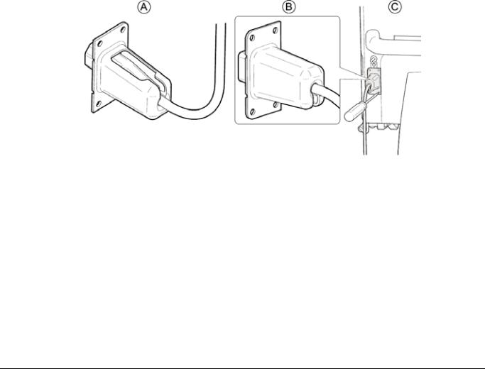
Connect Power Cord
Tool needed: Torx T-20
1. Select the appropriate power cord and cable support package.
Note: If the supplied power cord does not fit the wall socket, contact an authorized electrician that can connect the power cord to the wall socket.
2.Insert the power cord into the cable support, so that the cable support fits tightly against the female connector of the power cord.
(A)
3.Turn the cable support by half a turn so that the cable support guide is downward. (B)
4.Plug the power cord into the power cord socket on the rear panel of the Prismaflex control unit.
5.Using the 4 screws provided, secure the cable support to the studs on either side of the power cord socket. Tighten the screws using the Torx T-20. (C)
6.The Prismaflex control unit has a connection on the rear panel for a Potential Equalization Conductor. If required, connect the Potential Equalization Conductor to the connector.
Figure 2:1 Connecting the Power Cord
G5005209
Program version 7.xx
Installation Guide |
2:5 |

Install Scale Carrying Bars
Working one scale at a time, install the carrying bars into the bar trays of the four scales.
1.Open the scale, place a carrying bar on the bar tray.
2.Rotate the carrying bar so that the handle is pointing toward the floor; close the scale.
Note: Scale will not close properly unless the handle of the carrying bar is rotated toward the floor.
Figure 2:2 Placing the Carrying Bars on the Scales
Attachment of caution label
Tools needed: Cleaning Material
Perform the following steps to attach the caution labels to the front panel:
1.Clean the area of Prismaflex control unit where the stickers are to be placed according to point 3 in Visual Inspection and Cleaning on page 6:15.
2.Place the sticker next to the handle of the Effluent scale and the Replacement scale.
Note: The pictures on the stickers are not identical. Blue area on sticker is to be facing towards the Effluent scale and the Replacement scale.
2:6 |
Installation Guide |
G5005209 Program version 7.xx

3.Check that all stickers are firmly attached to the surface of the Prismaflex control unit.
4.Clean the surface on and around the stickers.
Change of Syringe Clip
Tools needed: Torx T-20
Perform the following steps to perform the change of the syringe clip:
1.Enter Service mode, Diagnose Screen - Syringe pump.
2.Using the syringe pump hard keys, move the plunger to its bottom position.
3.Switch off the Prismaflex control unit.
4.Remove the Torx screw (T-20).
5.Slide the syringe plate down.
6.Slide in the new syringe plate.
7.Fasten the screw that holds the syringe plate.
8.Select the correct size of the syringe clip and perform a configuration of the syringe holder, see Calibration Screen – Syringe Holder Configuration on page 6:87.
Prismaflex® Control Unit Calibrations
CAUTION
The installer is required to use an ESD (electro-static discharge) Grounding Wrist strap during this procedure to avoid unintentional damage to the electronic devices in the Prismaflex control unit.
Do not remove any cards or IC chips from their antistatic containers until you are ready to install them. When removing cards or chips from a system, immediately place them in an antistatic bag or container.
When handling cards or IC's, hold them by their edges. Avoid touching the components and connector leads on the card. Avoid touching the leads on the IC.
Do not slide cards or IC's over any surface. Avoid plastic, vinyl and Styrofoam in your work area.
CAUTION
Before first use of the Prismaflex control unit, the operations below must be performed in Service mode by an authorized service technician and recorded in the Maintenance Log (attached to the inside wall of the rear panel).
G5005209
Program version 7.xx
Installation Guide |
2:7 |

Calibration instructions are provided in Service Calibration Screens on page 6:58.
1.Plug the power cord into the wall socket and turn on the Prismaflex control unit.
2.Verify all scales, calibrate if necessary.
3.Verify the syringe pump, calibrate if necessary.
4.Check all pressure sensors, calibrate if necessary.
5.Set the time and date.
6.In service mode, select CALIBRATE –
LANGUAGE CONFIGURATION and install the required language.
7.Configure therapies, disposable sets, anticoagulation options, and blood warmer, if applicable.
As default the Prismaflex control unit is enabled for CRRT. Default filter set available is M60 and M100.
Electrical Safety Inspection
To ensure proper operation, an Electrical Safety Inspection (ESI) of the Prismaflex control unit shall be performed. Inspection is
performed according to instructions found in section “Electrical Safety Inspection” on page “6:4”. Test shall be documented in specific record and stored for future reference.
Installation Test
Note: Read the Service’s Manual before performing the installation test.
Before the first use of the Prismaflex control unit on a patient, the installation test must be performed with a Prismaflex CRRT set in place on the Prismaflex control unit. The installation test verifies that the Prismaflex control unit is properly installed. The test is performed using saline solution as a substitute for priming solution and fluid bags, and a container of water as a substitute for the patient. Successful completion of the installation test indicates that the Prismaflex control unit is functioning properly.
Supplies needed:
•Prismaflex CRRT set
•4 fluid bags (saline solution) 1000 ml each
•1 fluid container 1000 ml, filled with 500 ml tap water
•Catheter, 8F
2:8 |
Installation Guide |
G5005209 Program version 7.xx

To perform the installation test, follow the steps below;
1. |
Turn on the Prismaflex control unit. The Prismaflex control unit |
||||
|
performs an initialization test to check the system electronics, |
||||
|
startup signal sounds twice and status lights (green, red and yellow) |
||||
|
are lit during the test. |
|
|
||
2. |
Choose NEW PATIENT when the Choose Patient screen |
||||
|
appears and enter patient information. |
|
|||
3. |
Check that the SCUF, CVVH, CVVHD, CVVHDF softkeys |
||||
|
are available on the Choose Therapy screen. Choose the |
||||
|
CVVHDF therapy. |
|
|
|
|
4. |
Choose NO ANTICOAGULATION as |
|
|||
|
Anticoagulation Method. |
|
|||
5. |
Follow the instructions on the screen to load and prime the set. Use |
||||
|
saline solution as a substitute to priming and dialysate solutions. |
||||
|
The Prismaflex control unit performs multiple self-tests during |
||||
|
the priming cycle. |
|
|
|
|
6. |
When the prime and the prime test are completed, press |
||||
|
CONTINUE. The Enter Treatment Settings screen |
||||
|
appears. Set the Loss/Gain Limit to 140 ml/3h. Press |
||||
|
CONFIRM ALL. |
|
|
|
|
7. |
The Enter Flow Settings screen appears. Set the following |
||||
|
flow rates and press the CONFIRM ALL softkey. |
||||
|
|
|
|
|
|
Blood: |
PBP: |
Dialysate: |
Replacement: |
Fluid Removal Rate: |
|
180 ml/min |
1100 ml/h |
1200 ml/h |
1300 ml/h |
200 ml/h |
|
|
|
|
|
|
|
8. |
When the Review Prescription screen appears, verify the |
||||
|
above flow rates, then press CONTINUE. |
|
|||
9. |
When the Connect Patient screen appears, place the access |
||||
|
and return lines preferably connected through an 8F catheter into |
||||
|
the container of water. Press CONTINUE. |
|
|||
10. |
The Verify Patient Connection screen appears. Press |
||||
|
the START softkey, to enter Run mode. |
|
|||
Note: Because the installation test is performed with water, the Warning: Return Disconnection and
Advisory: Cannot Detect Return alarms could occur after the Prismaflex control unit has entered Run mode. If either of these alarms occur, press CONTINUE/OVERRIDE (depending on active alarm) and continue with the test. The alarms will not affect the outcome of the installation test.
11.Note the hour and minute on the Status screen when the Prismaflex control unit enters Run mode (this information can be found in History screen, pressing EVENTS softkey).
12.Run the installation test for at least 15 minutes.
G5005209
Program version 7.xx
Installation Guide |
2:9 |

13.Place a clamp on the access line (red) below the cartridge. The Warning: Access Pressure Extremely
Negative alarm should occur. Verify that the red light is flashing and the audible alarm sounds with a high sound, 10 sound pulses repeated approx. every 8 seconds.
14.Unclamp the access line and press the CONTINUE softkey on the Warning screen. Verify that the alarm is cleared (Warning screen leaves display, green light lit).
15.Check the Battery Backup function.
Note: Performed only if the Prismaflex control unit has Battery Backup installed. See section “Third Technical Screen” on page 4:32, Power section. Otherwise continue with step 19.
Disconnect the power cord from the wall socket. The Advisory: Main Power Lost alarm should occur. Verify that the yellow light is permanently lit and the audible alarm sounds with a low sound, 2 sound pulses repeated approx. every 21 seconds.
16.Press the OVERRIDE softkey. The Advisory screen leaves the display, but remains in Examine Alarms. Yellow light is lit, the Prismaflex control unit returns to the Status screen and the battery icon, in the top right corner of the display, is lit.
17.Connect the power cord to the wall socket. Verify that the battery icon disappears and that the Prismaflex control unit continues
in run mode. Verify that the alarm is cleared from the Examine Alarms (press SYSTEM TOOLS softkey and verify that the EXAMINE ALARMS softkey is not present) and green light lit.
18.Press the STOP softkey, then press the END TREATMENT softkey and follow the instructions to unload the set.
19.In service mode, select Diagnose Screen – PM timer and Date. Set and verify the PM timer.
20.Document the Prismaflex control unit configuration with either of the following:
-Download the logging data of the simulated treatment (LOX file) from the technical data card, and attach it to the GFS record, OR
-Download the logging data of the simulated treatment (LOX file) from the technical data card, and email it to barcode@gambro.com, OR
-Take a photo of the barcode in Service mode according to instructions in Service - Diagnose, 2D Barcode, and send it to barcode@gambro.com
21.Exit Service mode.
2:10 |
Installation Guide |
G5005209 Program version 7.xx
 Loading...