

Prismaflex
®
Service Manual
For use with software version 7.xx
Manufacturer:
Gambro Lundia AB
Box 10101, Magistratsvägen 16, SE-220 10 Lund, Sweden
Tel: +46-46-16 90 00, Fax: +46-46-16 96 96
www.gambro.com
Questions or comments about this publication can be directed to your local representative or to the manufacturer.
Order number:
G5005209
Copyright:
© 2005–2012 Gambro Lundia AB
Gambro, Prismaflex, Adsorba, Prismaflo, Prismacomfort, Prismatherm, MARSFLUX, diaFLUX, diaMARS, X-MARS,
septeX, oXiris, Hospal and MARS are trademarks belonging to the Gambro Group.
G5005209
Program version 7.xx

This page is intentionally left blank
Program version 7.xx
G5005209

Prismaflex®Service Manual
1. Before you get started
2. Installation Guide
3. Technical Description
4. Function Check
5. Alarms and Troubleshooting
6. Maintenance
7. Schematics
8. Specifications
9. Equations
G5005209
Program version 7.xx

Contents
1. Before you get started
AboutthisManual ...............................................
KeywordsUsedinthisManual .....................................
Complaint .....................................................
Responsibility and Disclaimer . .....................................
Safety Definitions ...............................................
Maintenance ...................................................
CompetenceofServiceEngineers ...................................
TechnicalSupport ...............................................
Symbols ......................................................
ElectricalSafety ..............................................
Instructionsandwarnings .......................................
Information .................................................
Communication ..............................................
Environmental ...............................................
Transportationandstorage ......................................
Solutions ...................................................
CertificationMarks ............................................
Disposal ......................................................
DisposalofDiscardedEquipment .................................
2. Installation Guide
1:2
1:2
1:3
1:3
1:4
1:5
1:5
1:5
1:6
1:6
1:6
1:7
1:8
1:8
1:8
1:9
1:10
1:10
1:10
AboutthisChapter .................................................
Installation .......................................................
Contents of Prismaflex
Electrical Requirement
Electromagnetic Envir
®
s ...........................................
onmentRequirements ...........................
olUnitShippingCarton ...................
Contr
SpaceRequirements .............................................
Unpacking and Assem
bly .........................................
Unpacking ..................................................
Connect Power Co
Install Scal
eCarryingBars ......................................
Attachment
Change of S
®
Prismafl
Electr
Insta
pdate .......................................................
SW u
libratethedisplay ................................................
Ca
3. Technical Description
ex
icalSafetyInspection .....................................
llationTest ..............................................
rd ...........................................
ofcautionlabel .....................................
yringeClip ........................................
ControlUnitCalibrations .............................
Prismaflex®ControlUnit ............................................
®
Prismaflex
Prismaflex
ControlUnitFunctions ..................................
®
ControlUnitComponents ...............................
FrontPanelComponents ..........................................
RearPanelComponents ...........................................
InteriorComponents .............................................
Interior—Door(Closedhatch) ................................
Interior—Door(Openedhatch) ...............................
2:2
2:3
2:3
2:4
2:4
2:4
2:4
2:4
2:5
2:6
2:6
2:7
2:7
2:8
2:8
2:11
2:12
3:2
3:2
3:3
3:3
3:14
3:16
3:16
3:16
Program version 7.xx
G5005209

Interior—Front1 ..........................................
Interior—Front2 ..........................................
Interior—Front3 ..........................................
Interior—Front4 ..........................................
ElectricalDescription ...............................................
InternalConnections .............................................
Modules ......................................................
PowerSupply ................................................
CarrierBoard ................................................
ControlCPU .................................................
ProtectiveCPUboard ..........................................
ARPSboard .................................................
PIBboard ...................................................
Alarmlightmodule ...........................................
LVDSinterfaceboard ..........................................
ExternalRS232board ..........................................
ExternalEthernetboard ........................................
ExternalRemoteAlarmConnector ................................
Fluidpumps .................................................
Bloodpump .................................................
Syringepump ................................................
Loader .....................................................
Scales ......................................................
ABDassembly ...............................................
Signals .....................................................
3:18
3:20
3:22
3:24
3:28
3:28
3:31
3:33
3:34
3:35
3:36
3:38
3:40
3:41
3:41
3:41
3:41
3:42
3:42
3:42
3:43
3:43
3:43
3:44
3:45
4. Function Check
AboutthisChapter .................................................
Main-controlledComponents ......................................
Self–tests ........................................................
Operating System Initialization .....................................
Initialization Test ................................................
PrimeSelf-test ..................................................
Pre-Prime ...................................................
Post-Prime ..................................................
PeriodicSelf-test ................................................
AlarmMonitoringDuringthePeriodicSelf-Test ......................
TechnicalScreens ..................................................
FirstTechnicalScreen ............................................
SecondTechnicalScreen ..........................................
ThirdTechnicalScreen ...........................................
FourthTechnicalScreen ..........................................
FifthTechnicalScreen ............................................
SixthTechnicalScreen ...........................................
5. Alarms and Troubleshooting
4:2
4:3
4:4
4:4
4:5
4:8
4:8
4:13
4:21
4:23
4:24
4:24
4:29
32
4:
:35
4
4:36
4:37
G5005209
Program version 7.xx
Aboutthischapter .................................................
WarningAlarms ...................................................
®
Prismaflex
ControlUnitActions ...................................
OperatorResponse ..............................................
OverriddenWarningAlarms .......................................
MalfunctionAlarms ................................................
5:2
5:3
5:3
5:3
5:4
5:5

Prismaflex®ControlUnitActions ...................................
OperatorResponse ..............................................
OverriddenMalfunctionAlarms ....................................
CautionAlarms ...................................................
®
Prismaflex
ControlUnitActions ...................................
OperatorResponse ..............................................
AdvisoryAlarms ..................................................
®
Prismaflex
ControlUnitActions ...................................
OperatorResponse ..............................................
OverriddenAdvisoryAlarms .......................................
Alarm Priorities . . .................................................
AlarmPriorityList ..............................................
Troubleshooting ...................................................
AbouttheTroubleshootingChapter ..................................
WarningAlarms ...................................................
CautionAlarms ...................................................
AdvisoryAlarms ..................................................
MalfunctionAlarms ................................................
Miscellaneous ....................................................
PowerFailure .....................................................
6. Maintenance
5:5
5:5
5:6
5:7
5:7
5:7
5:8
5:8
5:8
5:8
5:9
5:9
5:14
5:14
5:15
5:39
5:48
5:66
5:97
5:101
AboutthisChapter .................................................
ElectricalSafetyInspection ..........................................
General .......................................................
Visualinspection .............................................
PET-ProtectiveEarthTest ......................................
Note: ....................................................
Testequipment ............................................
Test .....................................................
CheckofConductivityClip .....................................
Testequipment ............................................
Test .....................................................
ELT/PLT ...................................................
Testequipment ............................................
General conditions for ELT / PLT ..............................
ELT-EarthLeakageCurrentTest ..............................
PLT-PatientLeakageCurrentTest .............................
Test .....................................................
RecordofElectricalSafetyInspection ................................
Visualinspection ...........................................
Remarks: .................................................
ConductivityClipTest .......................................
PET-ProtectiveEarthTest ...................................
ELT-EarthLekageCurrentTest ...............................
PLT-PatientLeakageCurrentTest ..............................
ComponentreplacementwithneededESI .............................
PreventiveMaintenance .............................................
ToolsNeeded ..................................................
WorkingTime ..................................................
®
Prismaflex
PMKit ..............................................
VisualInspectionandCleaning .....................................
ComponentReplacement ..........................................
6:3
6:4
6:4
6:5
6:5
6:5
6:5
6:5
6:6
6:6
6:6
6:6
6:6
6:6
6:6
6:7
6:8
6:9
6:
:9
6
6:9
6:9
6:10
6:10
6:12
6:13
6:13
6:14
6:14
6:15
6:17
9
Program version 7.xx
G5005209

PowerSupplyCheck .............................................
ExchangeofLeadBatteriesforBatteryBackup ......................
ServiceMode-CheckoutusingServiceDiagnoseMode ..................
ServiceScreens ...................................................
Service-DiagnoseScreens ...........................................
DiagnoseScreen–PumpsDiagnose .................................
DiagnoseScreen–ScaleDiagnose ..................................
Diagnose Screen – Pressure Pod Reposition . . . .........................
DiagnoseScreen–AlarmsToneandLight ............................
DiagnoseScreen–AirDetector .....................................
DiagnoseScreen–SyringePump ...................................
DiagnoseScreen–ClampandPinchValves ...........................
DiagnoseScreen–BLD(BloodLeakDetector) .........................
DiagnoseScreen–Internal ........................................
DiagnoseScreen–Communication ..................................
DiagnoseScreen–PMtimerandDate ................................
DiagnoseScreen–CleanScreen ....................................
Diagnose Screen – SW Configuration ................................
DiagnoseScreen–2DBarcode .....................................
ServiceCalibrationScreens ..........................................
Calibration Screen – Language Configuration ..........................
CalibrationScreen–ScalesCalibration ...............................
Calibration Screen – Pressure Sensors Calib
Calibration Screen – Syringe Pump Calibra
Calibration Screen – Filter Clotti
Calibration Screen – Set Clock an
Calibration Screen – Screen Bri
Calibration Screen – Pitch an
Calibration Screen – Extern
Calibration Screen – Ther
Calibration Screen –
Calibration Screen
Calibration Scre
Calibration Scr
Calibration S
Calibration
Calibrati
Calibra
Calibr
Funct
alCheck ......................................................
Fin
onScreen–SupplementarySyringe ...........................
tion Screen – Settings Handling ...............................
ation Screen – Blood Warmer Configuration ......................
ionalTest ....................................................
en–SerialNumber ..................................
een–AirDetector ...................................
creen–IPSettings ....................................
Screen – Syringe Holder Configuration ......................
apy/Sets Configuration ........................
Anticoagulation Configuration .....................
–AnticoagulationSolutions .........................
ngLimits ............................
dDate ..............................
ghtnessCalibration ......................
dVolume ...............................
alCommunicationInterface ..................
ration .......................
tion .........................
6:20
6:20
6:21
6:22
6:24
6:26
6:28
6:30
6:32
6:34
6:36
6:41
6:43
6:44
6:45
6:53
6:55
6:56
6:57
6:58
6:60
6:61
6:64
6:66
6:68
6:69
6:70
6:71
6:72
6:73
6:76
6:78
6:84
6:85
6:86
6:87
6:88
6:90
6:92
6:94
6:97
G5005209
Program version 7.xx
7. Schematics
8. Specifications
Performance ......................................................
FlowRatesandAccuracy .........................................
BloodFlowRate .............................................
AutomaticBloodReturnVolume .................................
ReplacementSolution/FluidFlowRate .............................
DialysateFlowRate ...........................................
PBPSolutionRate ............................................
Patient Fluid Removal Performance / Patient Plasma Loss Performance . . . .
8:3
8:3
8:3
8:3
8:3
8:3
8:4
8:4

EffluentFlowRate ............................................
Syringe Settings ................................................
Systemic, Prismaflexsyringepumpanticoagulationmethod .............
Citrate – Calcium, PrismaflexSyringePumpanticoagulationmethod ......
TPESettings ...................................................
Pressuresensorrange,accuracyandalarmlimits ........................
Access .....................................................
Return .....................................................
Filter ......................................................
Effluent ....................................................
Patientsafety ...................................................
AirBubbleDetector ...........................................
BloodLeakDetector ...........................................
Alarmsignals .....................................................
Audible .......................................................
Soundpressurelevels ..........................................
Characteristics ...............................................
Visual ........................................................
PhysicalData .....................................................
Weight,dimensions,etc. ..........................................
ScalesCharacteristics ............................................
ScaleWeightRange ...........................................
Scaleaccuracy: ...............................................
Power ........................................................
Linepower ..................................................
Batterybackup ...............................................
Externalcommunication ..........................................
Environmentaldata ................................................
Operation .....................................................
Transportation and Stora
ge ........................................
Noiselevel ....................................................
Vibrationlevels .................................................
Fluid spillage . . .................................................
Cleanability . . . .................................................
Electromagne
Electrical S
AC Leakage
Defibril
Radio F
romagnetic Compatibility .....................................
Elect
entialEqualization ............................................
Pot
ntinuousOperation ............................................
Co
onformitytoInternationalRules ......................................
C
ticEmissionsandImmunity .............................
afety ...................................................
Current .............................................
lation-proofAppliedPart ....................................
requencyInterference ......................................
Medical Device Classification ........................................
®
Prismaflex
DisposableSets ..........................................
CRRTDisposableSets ..............................................
Low flowsets ..................................................
Priming parameters and Blood flowrates ...........................
Patient fluid removal and Patient fluidloss/gainlimit ..................
Solution flowrates ............................................
Return Blood and Recirculation flowrates ..........................
High flowsets ..................................................
Priming parameters and Blood flowrates ...........................
Patient fluid removal and Patient fluidloss/gainlimit ..................
8:4
8:5
8:5
8:6
8:6
8:6
8:6
8:7
8:7
8:9
8:9
8:9
8:9
8:10
8:10
8:10
8:10
8:10
8:11
8:11
8:11
8:11
8:11
8:11
8:11
8:12
8:12
8:13
8:13
8:13
8:13
8:14
8:14
8:14
8:14
8:19
8:19
8:19
8:19
8:19
8:20
8:20
8:21
8:22
8:23
8:24
8:24
8:24
8:24
8:25
8:25
8:26
8:26
8:26
Program version 7.xx
G5005209

Solution flowrates ............................................
Return Blood and Recirculation flowrates ..........................
TPEDisposableSets ...............................................
Low flowsets ..................................................
Priming parameters and Blood flowrates ...........................
Return Blood and Recirculation flowrates ..........................
High flowsets ..................................................
Priming parameters and Blood flowrates ...........................
Return Blood and Recirculation flowrates ..........................
HPKits .........................................................
Priming parameters and Blood flowrates ..............................
Return Blood and Recirculation flowrates .............................
9. Equations
8:27
8:27
8:28
8:28
8:28
8:28
8:29
8:29
8:29
8:30
8:30
8:30
Blood pump flowrate ............................................
Filter pressure drop . . . ...........................................
Effluent flowrate ................................................
Transmembranepressure ..........................................
Totalpredilution ................................................
CRRTprescriptionindicators .......................................
Filtration Fraction ..........................................
Doses ...................................................
Patient fluidremoved .............................................
Accesstransmembranepressure ....................................
SoftwareCalculationsofTargetPatientPlasmaLoss .....................
FormulasusedinTPE ............................................
Patientplasmaloss ..............................................
PBP flowrate ..................................................
Syringe flowrate ................................................
9:2
9:2
9:2
9:3
9:3
9:3
9:3
9:4
9:5
9:5
9:5
9:6
9:6
9:7
9:7
G5005209
Program version 7.xx

This page is intentionally left blank
Program version 7.xx
G5005209

Chapter 1
Before you get started
AboutthisManual .....................................
KeywordsUsedinthisManual ...........................
Complaint ...........................................
Responsibility and Disclaimer . . ..........................
Safety Definitions .....................................
Maintenance .........................................
CompetenceofServiceEngineers .........................
TechnicalSupport .....................................
Symbols ............................................
ElectricalSafety ....................................
Instructionsandwarnings .............................
Information .......................................
Communication ....................................
Environmental .....................................
Transportationandstorage ............................
Solutions .........................................
CertificationMarks ..................................
Disposal ............................................
DisposalofDiscardedEquipment .......................
1:2
1:2
1:3
1:3
1:4
1:5
1:5
1:5
1:6
1:6
1:6
1:7
1:8
1:8
1:8
1:9
1:10
1:10
1:10
G5005209
Program version 7.xx
Prismaflex®Service Manual - Before you get started
1:1

About this Manual
This service manual provides the informationneededtoinstall
the Prismaflex control unit, to carry out maintenance, component
replacements and calibrations. It is a guidance on how to identify and
repair faults that may occur.
All available spare parts to be used for the Prismaflex control unit are
found in the illustrated Spare Parts List.
This service manual also provides a technical description of the
functionality of the Prismaflex control unit, including technical data.
Keywords Used in this Manual
Authorized service technicians
This term refers to Gambro trained and certified service technicians.
Filter
Depending on the therapy in use, Filter stands for either:
• Hemofilter/Dialyzer
• Plasmafilter
• Hemopurification cartridge
Manual
The term Manual refers to this Service Manual unless specified
differently.
Operator
In this manual, Operator designates appropriately trained and qualified
clinical staff who is in charge of t
he Prismaflex control unit. The
operator sets the prescribed values in accordance with the prescribed
treatment, responds to alarms, troubleshoots the Prismaflex control
unit, handles the bags, etc.
Once the training material is read
through and understood, the operator is approved to operate the
Prismaflex control unit. The operator works within one meter from the
front of the Prismaflex co
ntrol unit.
Responsible Organization
In this manual, Responsible Organization means a function or a person
who can identify, analyze, and control potential risks that could occur,
for example, when connecting the Prismaflex control unit to other
equipment or when making changes to the equipment connected to
the Prismaflex control unit.
1:2
Screens
The Prismaflex control unit displays different screens during operation.
Whenever a screen is referred t o in this manual, it is identified by its
title, e.
g. Enter Flow Settings screen or Status screen.
®
Prismaflex
Service Manual - Before you get started
G5005209
Program version 7.xx

Softkeys
Whenever a Softkey on the Prismaflex screen is referred to in this
manual, it is written in capital italic letters, e.g. NEW PATIENT or
CHANGE BAG.
Training Material
The operator's manual is the primary training material for staff who is
to operate the Prismaflex system. See section “Competence of Service
Engineers” on page 1:5, for information concerning the minimum level
of competence required for service engineers.
Complaint
If a c omplaint is raised it shall be communicated to the relevant Gambro
Sales Company. In order for the Sales Company to be able to determine
the relevance of a complaint, it is of vital importance that the deviation
is communicated to them as comprehensive as the issue requires.
Responsibility and Disclaimer
Gambro accepts responsibility for the safety, reliability, and
performance of this equipment only:
• If any modifications to the equipment have been authorized in
writing by Gambro and carried out by an authorized service
technician.
• If the electrical installation for powering the equipment complies
with all applicable local electrical codes and requirements
including, if applicable, IEC requirements.
• If the equipment is used in accordance with the Service Manual
and the Operator's Manual.
Gambro will provide, on request, a service manual which contains
all necessary circuit diagrams, calibration instructions, and service
information to enable authorized service technicians to repair those
parts of t his equipment which Gambro considers to be repairable.
Gambro does not accept any responsibility or liability for use of
accessories or disposables other than those specified in this manual
or if any specified accessory or disposable is not used in accordance
with this manual, online instructions and the Instructions for Use
accompanying those accessories and disposables.
Since Gambro has no control over service work which is not
performed by authorized service technicians, Gambro will in no way
be responsible or liable for any damages resulting from the operation
or performance of a ny device, or any i njury caused thereby, after repair
has been performed by any person other than an authorized service
technician of Gambro.
G5005209
Program version 7.xx
Prismaflex®Service Manual - Before you get started
1:3

Under no circumstances will Gambro be liable for any indirect,
incidental, special or consequential damages of any kind, its liability
being hereby limited solely to repair or replacement.
Safety Definitions
This manual uses the following s afety definitions :
WARNING
A warning alerts the reader about a situation which, if not avoided,
could result in an adverse reaction, injury or death.
WARNING
CAUTION
A caution alerts the reader about a situation which, if not avoided,
could result in minor or moderate injury to the user or patient or
damage to the equipment or other property.
CAUTION
Note: Notes are added to give more information.
1:4
Prismaflex
®
Service Manual - Before you get started
G5005209
Program version 7.xx

Maintenance
To ensure proper operation of the Prismaflex control unit, an authorized
service t echnician must perform a complete series of maintenance
procedures at regular intervals.
The maintenance and calibration information is provided in this
Service Manual, see Preventive Maintenance on page 6:13.
It is mandatory to perform at least one preventive maintenance once a
year or every 6000 hour. The rate of preventive maintenance might be
different due to variations of the operating environment.
Competence of Service Engineers
There is a certain minimum level of competence required for Service
Engineers who maintain and repair Gambro products, summarized
as follows.
A Service Engineer is considered authorized if he/she has:
1. Attended Prismaflex technical service course and has been given a
certificate stating that the technician has passed the course.
2. Access to the recommended test equipment and special tools
detailed in this Service Manual.
3. Access to the recommended Prismaflex control unit - Spare parts
List.
4. Access to and understanding of the Prismaflex control unit - Service
manual and the Prismaflex control unit - Operator's Manual.
In general, this policy implies that training will be carried out by
Gambro Lundia AB, while local markets are responsible for their own
service organization.
Technical Support
For technical support please contact your local Gambro Service
representative or visit the website.
G5005209
Program version 7.xx
Prismaflex®Service Manual - Before you get started
1:5
Symbols
If applicable, the following symbols appear on or near the serial
number label or other permanently affixed labels of this device. For
more information, see chapter 8: “Specifications” on page 8:2.
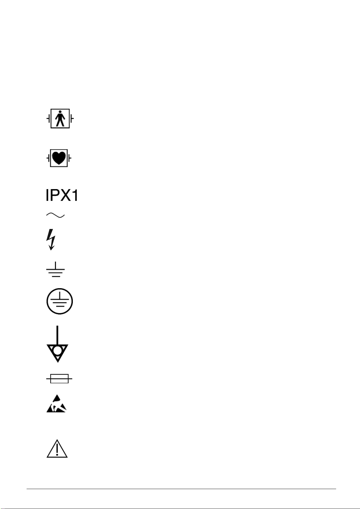
Electrical Safety
Equipment applied part is Type BF, defibrillation - proof per IEC
60601-1.
Note: TobesureofthePrismaflex control unit’s classification see type
label found at the back of the Prismaflex control unit.
Equipment applied part is Type CF, defibrillation-proof per IEC
60601-1.
Note: TobesureofthePrismaflex control unit’s classification see type
label found at the back of the Prismaflex control unit.
Device meets the “drip proof” classification requirements.
Device requires an alternating supply current.
Nearby high-voltage conductors could be hazardous if contacted.
This symbol is located near functional ground locations on this device.
This symbol is located near protective ground locations on this device.
This symbol identifies the point of connection of a potential
equalization conductor.
The terminal is c onnected to the chassis and should be connected to
corresponding terminals on other equipment in order to eliminate
potential differences.
Fuse.
Certain components within this equipment are sensitive to electrostatic
discharge.
1:6
Instructions a
nd warnings
Attention, consult accompanying documents.
®
Prismaflex
Service Manual - Before you get started
G5005209
Program version 7.xx
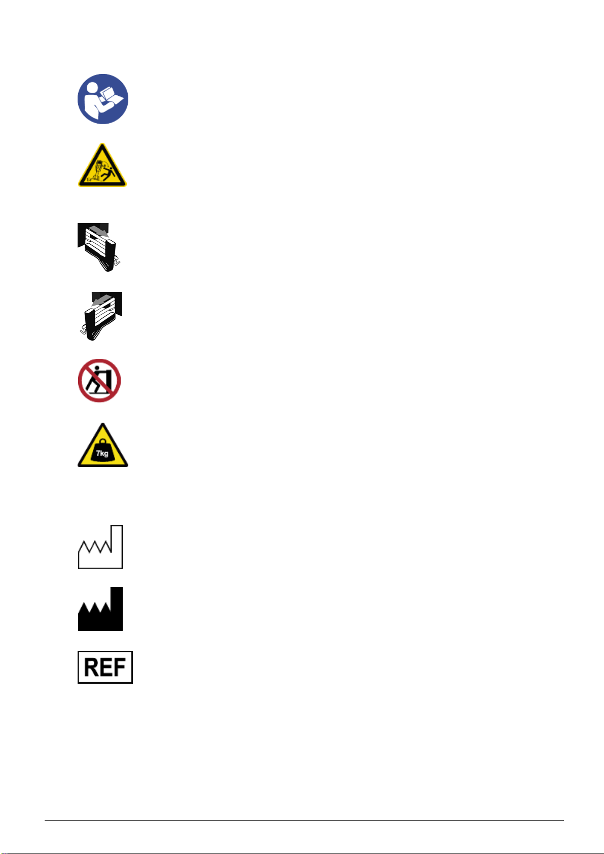
Read instructions before use.
This symbol warns against an incline of the Prismaflex control unit of
more than 5° from the floor.
Note: This warning label must be applied on the warmer holder before
use. It should be mounted on deliverance. The background color is
yellow.
Pull out scale completely before hanging bag.
Pull out scale completely before hanging bag.
Risk of tipping the Prismaflex control unit from pushing, leaning,
resting, etc. The colors are red, white, and black.
This symbol is applied on the stand if t he Prismaflex calibration weight
kit is stored inside. Calibration weights are to be removed before tilting
the Prismaflex control unit into horizontal position.
The color is black on a yellow background.
Information
Date of manufacture with year as four digits.
Manufacturer. The year of manufacture may be included in the symbol
expressed as four digits.
Catalog number.
G5005209
Program version 7.xx
Prismaflex®Service Manual - Before you get started
1:7
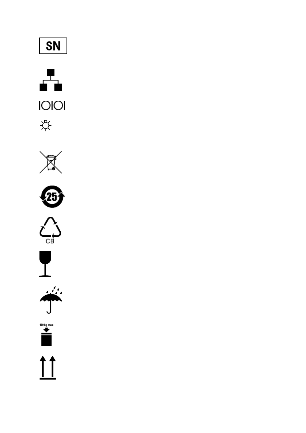
Serial number.
Communication
Ethernet port.
RS232 Serial Communication port.
Remote alarm connection.
Environmental
This symbol indicates that:
– since the equipment contains dangerous substances, it must be
recycled rather than disposed together with other municipal waste;
– the equipment was placed on the market after 13 August 2005.
The device contains toxic or hazardous substances or elements.
Recycle the cardboard.
Transportation and storage
Fragile – handle with care.
Keep dry.
The maximum stacking load permitted on the transport package is
100 kg.
This end up.
1:8
Prismaflex
®
Service Manual - Before you get started
G5005209
Program version 7.xx
Atmospheric pressure limitation. Upper and lower limits are expressed
with numeric values in kPa.
Humidity limitation. Upper and lower limits are expressed with
numeric values in %.
Temperature limitation. Upper and lower limits are expressed with
numeric values in degrees Celsius or Fahrenheit.
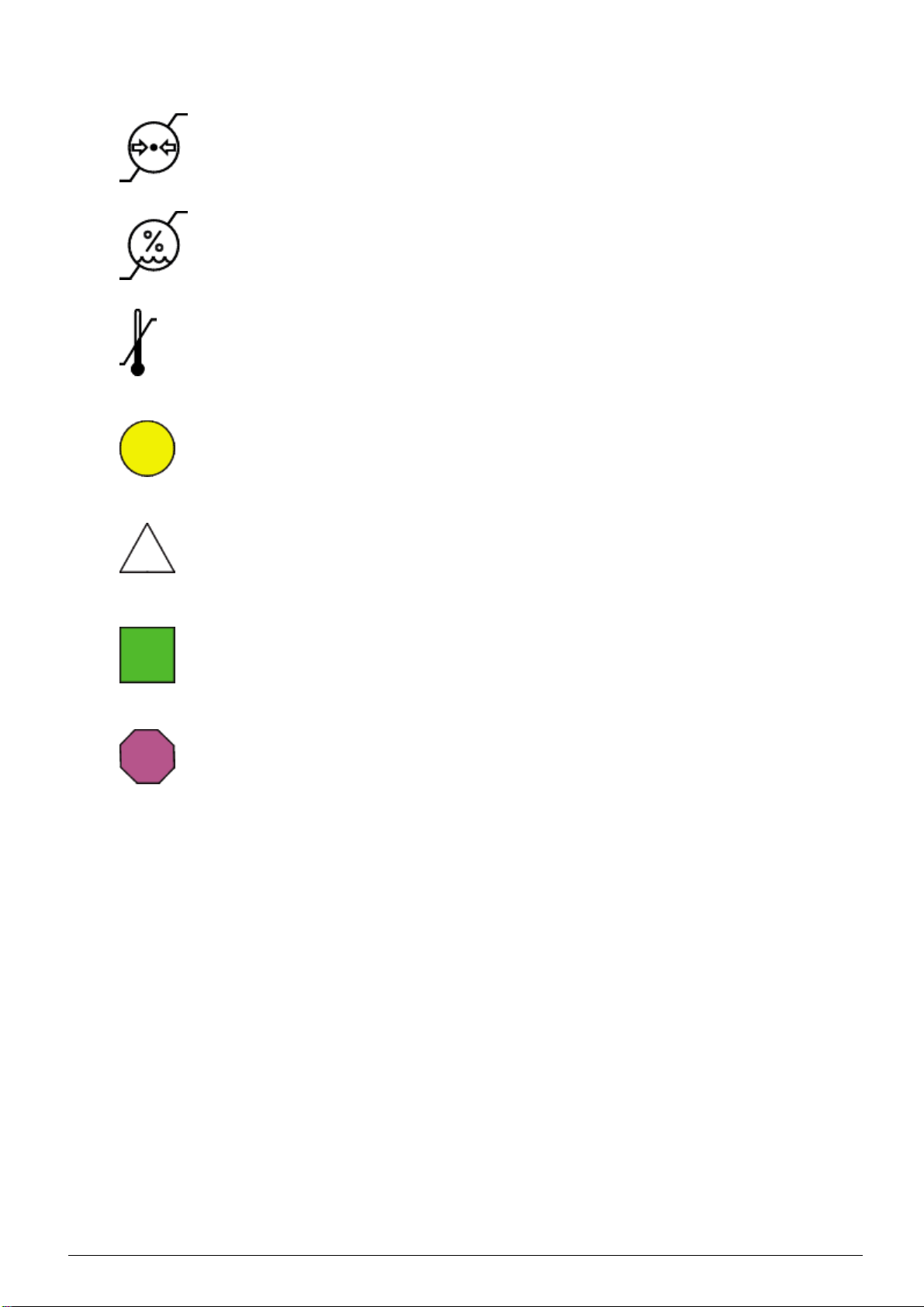
Solutions
Circle sign; placed as colored symbol on effluent scale and in the
graphical user interface in screens related to effluent. On the disposable
set the symbol is a relief shape in the plastic cover indicating the
effluent pump.
Triangle sign; placed as colored symbol on PBP scale and in the
graphical user interface in screens related to PBP. On the disposable
set the symbol is a relief shape in the plastic cover indicating the PBP
pump.
Square sign; placed as colored symbol on dialysate scale and in
the graphical user interface in screens related to dialysate. On the
disposable set the symbol is a relief shape in the plastic cover indicating
the dialysate pump.
Octagon sign; placed as colored symbol on replacement scale and in
the graphical user interface in screens related to replacement. On
the disposable set the symbol is a re
lief shape in the plastic cover
indicating the replacement pump.
G5005209
Program version 7.xx
Prismaflex®Service Manual - Before you get started
1:9

Certification Marks
The CE-conformity mark indicates that the Prismaflex control unit
conforms to the requirements in the EC Council Directive 93/42/EEC
of 14 June, 1993 concerning medical devices. It also indicates that
the notified body British Standards Institution (BSI, No. 0086) has
approved the Quality Management System. The CE conformity mark
is only valid for the Prismaflex control unit. Disposables and any
accessories specified for use with the Prismaflex control unit are
marked with CE conformity marks in their own right.
The CSA (C-US) mark indicates that the Prismaflex control unit
conforms to the requirements related to safety of medical d evices for
the US and Canada. The “C” and the “US” adjacent to the CSA mark
indicate that the Prismaflex control unit has been evaluated to the
applicable ANSI/UL and CSA standards for use in the US and Canada.
The CCC mark indicates that the Prismaflex control unit conforms to
the safety requirements for China Compulsory Certification (CCC) as
described by the competent authority Certification and Accredi
tation
Administration of People's Republic of China (CNCA). The “S”
adjacent to the CCC mark indicates that safety requirements are met.
Disposal
The Prismaflex control unit shipping carton, foam packing, and
other packaging material should be disposed of according to local
regulations.
For the purpose of protecting the environment the Prismaflex control
unit must not be disposed with general domestic waste, but shall be
separately collected for dismantling and recovery. Where applicable
national regulations shall be applied. Consult your relevant Gambro
Sales Company for information.
Disposal of Discarded Equipment
Discarded electromedic
with municipal waste but must be collected separately in order to
guarantee ecologically correct disposal to prevent dispersion of
potential pollutant
Pay attention to the fact that some components of the Prismaflex control
unit (display, ba
tteries, circuit boards, etc.) may contain toxic
substances which, if released into the environment, pose a risk to the
health of living organisms and the environment itself.
al equipment must not be disposed together
s into the environment.
1:10
The Prismaflex control unit contains a lithium energy cell and
a lead-acid battery. The lithium energy cell is embedded in a
semiconduc
tor on the monitor circuit card assembly. When replacing
these components, follow local regulations for proper disposal.
®
Prismaflex
Service Manual - Before you get started
G5005209
Program version 7.xx

Chapter 2
Installation Guide
Contents
AboutthisChapter .......................................
Installation .............................................
®
Contents of Prismaflex
ElectricalRequirements .................................
ElectromagneticEnvironmentRequirements .................
SpaceRequirements ...................................
UnpackingandAssembly ...............................
Unpacking ........................................
ConnectPowerCord .................................
InstallScaleCarryingBars ............................
Attachmentofcautionlabel ...........................
ChangeofSyringeClip ..............................
®
Prismaflex
ElectricalSafetyInspection ...........................
InstallationTest ....................................
SWupdate .............................................
Calibratethedisplay ......................................
ControlUnitCalibrations ...................
ControlUnitShippingCarton .........
2:2
2:3
2:3
2:4
2:4
2:4
2:4
2:4
2:5
2:6
2:6
2:7
2:7
2:8
2:8
2:11
2:12
G5005209
Program version 7.xx
Installation Guide
2:1

About this Chapter
This chapter describes the installation procedure of the
Prismaflex control unit. The installation must be performed by an
authorized service technician.
2:2
Installation Guide
G5005209
Program version 7.xx

Installation
WARNING
Read these installation instructions before starting installation.
Read the Prismaflex Service Manual and perform the installation
test before first use.
All electrical installations must comply with all applicable local
electrical codes and manufacturer specifications.
The assembled Prismaflex control unit weighs approximately 78 kg
(172 lb). Use at least two people to lift it out of the shipping carton.
Handle the Prismaflex control unit carefully.
WARNING
Contents of Prismaflex®Control Unit Shipping Carton
Each Prismaflex control unit is pre-attached to a column and a base
with casters. The Prismaflex control unit comes packaged with the
following items:
• Installation kit:
- United States-style power cord, with retaining bracket
- Continental European-style power cord, with retaining bracket
-4screws
- 4 scale carrying bars
• 20 ml syringe clip
• Pump crank
• Caution stickers
• Potential equalization connector
• Prismaflex Operator’s manual on CD
G5005209
Program version 7.xx
Installation Guide
2:3

Electrical Requirements
The Prismaflex control unit operates from an electrical power source
that delivers the following:
• from 100 (–10%) Vac to 240 (+10%) Vac; from 45 Hz to 65 Hz
It is essential that the power socket is properly grounded and in good
condition. If there is any doubt regarding the condition of the power
cord, have the wiring checked by a qualified electrician.
Electromagnetic Environment Requirements
The Prismaflex control unit requires special precautions regarding
EMC and needs to be installed and put into service according to the
EMC information provided in the Operator’s Manual.
Space Requirements
The assembled Prismaflex control unit requires a minimum of 63 cm
× 63 cm (25 in × 25 in) of floor space. There must be enough space
around the Prismaflex control unit so that all fluid bags can hang freely
from the scale carrying bars.
Unpacking and Assembly
CAUTION
Be careful when you move the Prismaflex control unit, so that you
don't make it fall over.
CAUTION
Unpacking
1. Open the shipping carton. C
out of the carton and place it upright. Carefully remove the foam
packing and pay attention not to damaging the Prismaflex control
unit components. Dispo
and other packaging material according to local regulations.
2. Inspect all components, paying particular attention to the front
panel of the Prisma
flex control unit. If any damage has occurred,
immediately contact your local sales or service representative.
arefully lift the Prismaflex control unit
se of the shipping carton, foam packing,
2:4
Installation Guide
G5005209
Program version 7.xx
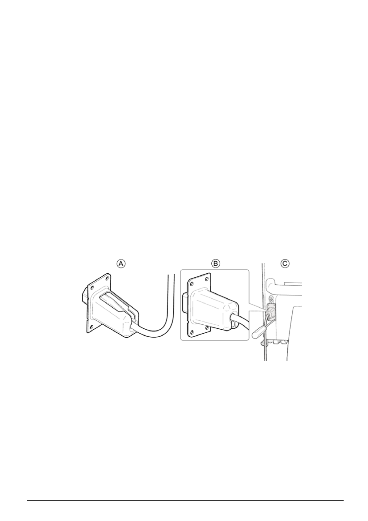
Connect Power Cord
Tool needed: Torx T-20
1. Select the appropriate power cord and cable support package.
Note: If the supplied power cord does not fit the wall socket, contact
an authorized electrician that can connect the power cord to the wall
socket.
2. Insert the power cord into the cable support, so that the cable
support fits tightly against the female connector of the power cord.
(A)
3. Turn the cable support by half a turn so that the cable support
guide is downward. (B)
4. Plug the power cord into the power cord socket on the rear panel
of the Prismaflex control unit.
5. Using the 4 screws provided, secure the cable support to the studs
on either side of the power cord socket. Tighten the screws using
the Torx T-20. (C)
6. The Prismaflex control unit has a connection on the rear panel
for a Potential Equalization Conductor. If require
d, connect the
Potential Equalization Conductor to the connector.
Figure 2:1 Connecting the Power Cord
G5005209
Program version 7.xx
Installation Guide
2:5
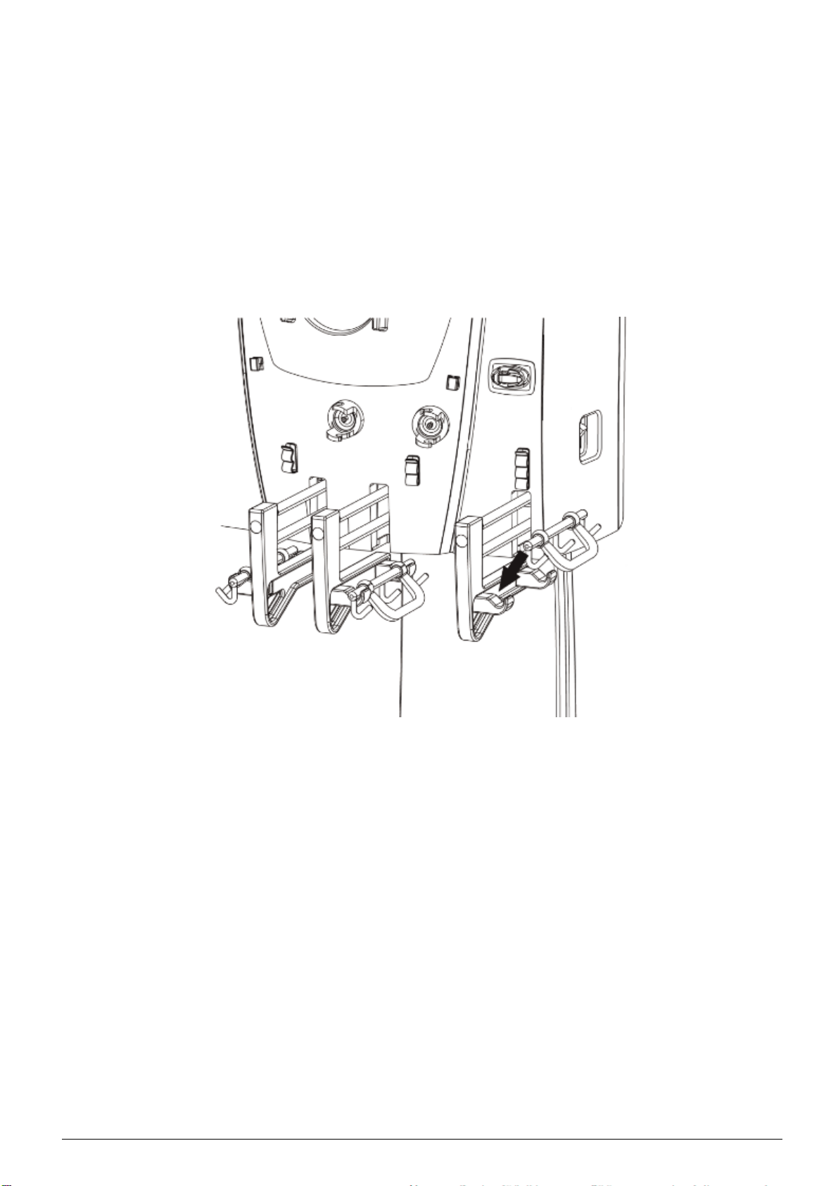
Install Scale Carrying Bars
Working one scale at a time, install the carrying bars into the bar trays
of the four scales.
1. Open the scale, place a carrying bar on the bar tray.
2. Rotate the carrying bar so that the handle is pointing toward the
floor; close the scale.
Note: Scale will not close properly unless the handle of the carrying
bar i s rotated toward the floor.
Figure 2:2 Placing the Carrying Bars on the Scales
Attachment of caution label
Tools needed: Cleaning Material
Perform the following steps to attach the caution labels to the front
panel:
1. CleantheareaofPrismaflex control unit where the stickers are to
be placed according to point 3 in Visual Inspection and Cleaning
on page 6:15.
2. Place the sticker next to the handle of the Effluent scale and the
Replacement scale.
Note: The pictures on the stickers are not identical. Blue area on sticker
is to be facing towards the Effluent scale and the Replacement scale.
2:6
Installation Guide
G5005209
Program version 7.xx

3. Check that all stickers are firmly attached to the surface of the
Prismaflex control unit.
4. Clean the surface on and around the stickers.
Change of Syringe Clip
Tools needed: Torx T-20
Perform the following steps to perform the change of the syringe clip:
1. Enter Service mode, Diagnose Screen - Syringe pump.
2. Using the syringe pump hard keys, move the plunger to its bottom
position.
3. Switch off the Prismaflex control unit.
4. Remove the Torx screw (T-20).
5. Slide the syringe plate down.
6. Slide in the new syringe plate.
7. Fasten the screw that holds the syringe plate.
8. Select the correct size of the syringe clip and perform a
configuration of the syringe holder, see Calibration Screen –
Syringe Holder Configuration on page 6:87.
®
Prismaflex
CAUTION
The installer is required to use an ESD (electro-static discharge)
Grounding Wrist strap during this procedure to avoid unintentional
damage to the electronic dev
Do not remove any cards or IC chips from their antistatic containers
until you are ready to inst
from a system, immediately place them in an antistatic bag or
container.
When handling cards or IC's, hold them by their edges. Avoid
touching the components and connector leads on the card. Avoid
touching the lead
Control Unit Calibrations
ices in the Prismaflex control unit.
all them. When removing cards or chips
sontheIC.
G5005209
Program version 7.xx
Do not slide cards or IC's over any surface. Avoid plastic, vinyl
and Styrofoam i
n your work area.
CAUTION
Before first use of the Prismaflex control unit, the operations below
must be per
formed in Service mode by an authorized service technician
and recorded in the Maintenance Log (attached to the inside wall of
the rear panel).
Installation Guide
2:7

Calibration instructions are provided in Service Calibration Screens on
page 6:58.
1. Plug the power cord into the wall socket and turn on the
Prismaflex control unit.
2. Verify all scales, calibrate if necessary.
3. Verify the syringe pump, calibrate if necessary.
4. Check all pressure sensors, calibrate if necessary.
5. Set the time and date.
6. In service mode, select CALIBRATE –
LANGUAGE CONFIGURATION and install the required language.
7. Configure therapies, disposable sets, a nticoagulation options, and
blood warmer, if applicable.
As default the Prismaflex control unit is enabled for CRRT. Default
filter set available is M60 and M100.
Electrical Safety Inspection
To ensure proper operation, an Electrical Safety Inspection (ESI)
of the Prismaflex control unit shall be performed. Inspection is
performed according to instructions found in section “Electrical Safety
Inspection” on page “6:4”. Test shall be documented in specificrecord
and stored for future reference.
Installation Test
Note: Read the Service’s Manual before performing the installation
test.
Before the first use of the Prismaflex control unit on a patient, the
installation test must be p
erformed with a Prismaflex CRRT set in
place on the Prismaflex control unit. The installation test verifies that
the Prismaflex control unit is properly installed. The test is performed
using saline solution a
s a substitute for priming solution and fluid bags,
and a container of water as a substitute for the patient. Successful
completion of the installation t est indicates that the Prismaflex control
unit i s functionin
g properly.
Supplies needed:
2:8
• Prismaflex CRRT set
• 4 fluid bags (saline solution) 1000 ml each
• 1 fluid conta
iner 1000 ml, filled with 500 ml tap water
• Catheter, 8F
Installation Guide
G5005209
Program version 7.xx

To perform the installation test, follow the steps below;
1. Turn on the Prismaflex control unit. The Prismaflex control unit
performs an initialization test to check the system electronics,
startup signal sounds twice and status lights (green, red and yellow)
are lit during the test.
2. Choose NEW PATIENT when the Choose Patient screen
appears and enter patient information.
3. Check that the SCUF, CVVH, CVVHD, CVVHDF softkeys
are available on the Choose Therapy screen. Choose the
CVVHDF therapy.
4. Choose NO ANTICOAGULATION as
Anticoagulation Method.
5. Follow the instructions on the screen to load and prime the set. Use
saline solution as a substitute to priming and dialysate solutions.
The Prismaflex control unit performs multiple self-tests during
the priming cycle.
6. When the prime and the prime test are completed, press
CONTINUE.The Enter Treatment Settings screen
appears. Set the Loss/Gain Limit to 140 ml/3h. Press
CONFIRM ALL.
7. The Enter Flow Settings screen appears. Set the f
ollowing
flow rates and press the CONFIRM ALL softkey.
Blood:
180 ml/min
PBP:
1100 ml/h
Dialysate:
1200 ml/h
Replacement:
1300 ml/h
Fluid Removal Rate:
200 ml/h
8. When the Review Prescription screen appears, verify the
above flow rates, then press CONTINUE.
9. When the Connect Patient screen ap
pears, place the access
and return lines preferably connected through an 8F catheter into
the container of water. Press CONTINUE.
10. The Verify Patient Connect
ion screen appears. Press
the START softkey, to enter Run mode.
Note: Because the installation test is performed with
water, the Warning:
Return Disconnection and
Advisory: Cannot Detect Return alarms could occur
after the Prismaflex control unit has entered Run mode. If either of
these alarms occu
r, press CONTINUE/OVERRIDE (depending on
active alarm) and continue with the test. The alarms will not affect the
outcome of the installation test.
G5005209
Program version 7.xx
11. Note the hour
and minute on the Status screen when the
Prismaflex control unit enters Run mode (this information can be
found in History screen, pressing EVENTS softkey).
12. Run the in
stallation test for at least 15 minutes.
Installation Guide
2:9

13. Place a clamp on the access line (red) below the cartridge.
The Warning: Access Pressure Extremely
Negative alarm should occur. Verify that the red light is flashing
and the audible alarm sounds with a high sound, 10 sound pulses
repeated approx. every 8 seconds.
14. Unclamp the access line and press the CONTINUE softkey
on the Warning screen. Verify that the alarm is cleared
(Warning screen leaves display, green light lit).
15. Check the Battery Backup function.
Note: Performed only if the Prismaflex control unit has Battery
Backup installed. See section “Third Technical Screen” on page
4:32, Power section. Otherwise continue with step 19.
Disconnect the power cord from the wall socket. The
Advisory: Main Power Lost alarm should occur. Verify
that the yellow light is permanently lit and the audible alarm
sounds with a low sound, 2 sound pulses repeated approx. every
21 seconds.
16. Press the OVERRIDE softkey. The Advisory screen leaves the
display, but remains in Examine Alarms. Yellow light is lit, th
e
Prismaflex control unit returns to the Status screen and the battery
icon, in the top right corner of the display, is l it.
17. Connect the power cord to the wall socket. Verify t
hat the battery
icon disappears and that the Prismaflex control unit continues
in run mode. Verify that the alarm is cleared from the Examine
Alarms (press SYSTEM TOOLS softkey and verify
that the
EXAMINE ALARMS softkey is not present) and green light lit.
18. Press the STOP softkey, then press the END TREATMENT softkey
and follow the instructions to unloa
dtheset.
19. In service mode, select Diagnose Screen – PM timer and Date.Set
and verify the PM timer.
20. Document the Prismaflex cont
rol unit configuration with either of
the following:
- Download the logging data of the simulated treatment (LOX
file) from the technical
data card, and attach it to the GFS
record, OR
- Download the logging data of the simulated treatment
(LOX file) from the
technical data card, and email it to
barcode@gambro.com, OR
2:10
- Take a photo of the barcode in Service mode according to
instruction
s in Service - Diagnose, 2D Barcode, and send it to
barcode@gambro.com
21. Exit Service mode.
Installation Guide
G5005209
Program version 7.xx

SW update
1. Check that the machine is switched off.
2. Open the cabinet using an 8 mm Hex key.
3. Swing open the bracket mounted with protective and PIB board
to access the PC-board.
4. Connect a PC keyboard to the PS2 connector on the PC 104 board.
5. Turn on the machine and insert the software upgrade CD into the
CD-player.
Note! Software 7.xx requires PC-104 board (PCM-9375) to work.
6. Switch the main switch to OFF to restart the machine, wait 5
seconds and switch it ON again to boot from the CD.
7. A list with different boot setups is displayed.
8. Press 1 on the PC keyboard to start the software download –
“Initiate all”.
9. A question appears; do you want to continue, press Y on the PC
keyboard.
10. When the software upgrade is complete a messa
ge “Press any key
to continue.” occurs.
11. Remove the software CD and PC keyboard.
12. Switch the main switch to OFF to rest
art the machine, wait 5
seconds and switch it ON again.
G5005209
Program version 7.xx
Installation Guide
2:11

Calibrate the display
1. Make sure that the Prismaflex control unit is switched OFF before
starting the procedure.
2. Open the back door using the 8 mm Hex tool.
3. Set the SW1 (Dip Switch 1), on the Carrier board, to the ON
position.
4. Turn on the Prismaflex control unit and follow the instructions
given on the screen.
5. Turn off the Prismaflex control unit when the message
Press STOP to convaliate the calibr. appears or
press SET(S).
6. Set the switch SW1 (Dip Switch 1), to the OFF position.
2:12
Installation Guide
G5005209
Program version 7.xx

Chapter 3
Technical Description
Contents
Prismaflex®ControlUnit ..................................
®
Prismaflex
Prismaflex
FrontPanelComponents ................................
RearPanelComponents .................................
InteriorComponents ...................................
ElectricalDescription .....................................
InternalConnections ...................................
Modules ............................................
PowerSupply ......................................
CarrierBoard ......................................
ControlCPU .......................................
ProtectiveCPUboard ................................
ARPSboard .......................................
PIBboard .........................................
Alarmlightmodule .................................
LVDSinterfaceboard ................................
ExternalRS232board ................................
ExternalEthernetboard ..............................
ExternalRemoteAlarmConnector ......................
Fluidpumps .......................................
Bloodpump .......................................
Syringepump ......................................
Loader ...........................................
Scales ............................................
ABDassembly .....................................
Signals ...........................................
ControlUnitFunctions ........................
®
ControlUnitComponents .....................
Interior—Door(Closedhatch) ......................
Interior—Door(Openedhatch) .....................
Interior—Front1 ................................
Interior—Front2 ................................
Interior—Front3 ................................
Interior—Front4 ................................
3:2
3:2
3:3
3:3
3:14
3:16
3:16
3:18
3:20
3:22
3:24
3:26
3:28
3:28
3:31
3:33
3:34
3:35
3:36
3:38
3:40
3:41
3:41
3:41
3:41
3:42
3:42
3:42
3:43
3:43
3:43
3:44
3:45
G5005209
Program version 7.xx
Technical Description 3:1

Prismaflex®Control Unit
The Prismaflex control unit is pre-attached to a column and a base with
casters. For installation see Installation Guide on page 2:1.
Prismaflex®Control Unit Functions
The Prismaflex control unit is a software-controlled device that
performs the following functions:
• Loads and primes the Prismaflex disposable set automatically.
• Pumps blood through the blood flowpath of the
Prismaflex disposable set.
• Delivers anticoagulant solution into the blood flowpath.
• Pumps sterile infusion solutions into the blood flowpath of the
Prismaflex disposable set, according to therapy in use.
• Pumps sterile dialysate into the fluid compartment of the filter in
CRRT therapies.
• Controls the patient fluid removal or plasma loss, according to
the therapy in use.
• Monitors the system and alerts the operator to abnormal situations
through alarms.
3:2 Technical Description
G5005209
Program version 7.xx

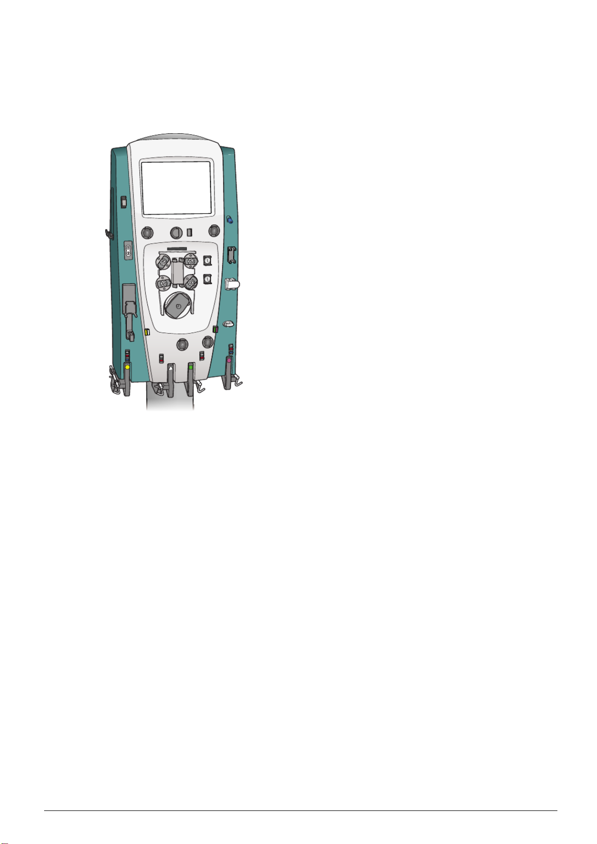
Prismaflex®Control Unit Components
The Prismaflex control unit components are divided into:
• Front Panel
• Rear Panel
• Interior Components
Front Panel Components
The front panel components of the Prismafl ex control unit are
illustrated and described in the following figures.
• Figure 3:1 on page 3:4 shows the pumps.
• Figure 3:2 on page 3:6 shows the pressure components.
• Figure 3:3 on page 3:8 shows sensors and clamps.
• Figure 3:4 on page 3:10 shows the scale components.
• Figure 3:5 on page 3:12 shows miscellaneous components.
G5005209
Program version 7.xx
Technical Description 3:3

Figure 3:1 Pumps
1. Dialysate/replacement 2 pump
CVVHD, CVVHDF: Pumps
dialysate solution into the fluid
compartment of the filter.
CVVH: If post-filt
er replacement delivery has been chosen and
replacement solution has been placed on the green scale, this pump
delivers replacement solution into the post-filter blood flowpath.
2. Replacem
ent pump
Pumps replacement solution/fluid into the blood flowpath.
CRRT: Rep
lacement solution can be delivered either pre- or
post-filter.
TPE: Re
3:4 Technical Description
placement fluid is always delivered 100% post filter.
G5005209
Program version 7.xx

3. Blood pump
Pumps blood through the blood flowpath of the Prismaflex disposable set.
4. Pre-blood pump (PBP)
If required, pumps a solution i nto the blood access line at a location
immediately after patient blood enters the line and before the blood
pump.
In “Citrate – Calcium, Prismaflex syringe pump” anticoagulation
the PBP is the pump infusing the citrate solution into the blood
access line.
5. Syringe pump assembly
The pump assembly holds the solution-filled syringe and controls
the rate of delivery. Delivery can be continuous or in boluses.
In “Systemic, Prismaflex syringe pump” anticoagulation method,
the syringe pump delivers anticoagulant into the blood flowpath.
In “Citrate – Calcium, Prismaflex syringe pump” anticoagulatio
method, the syringe pump delivers calcium solution into patient via
a separate central venous access.
6. Effluent pump
CRRT: Pumps ultrafiltrate/dialysate; a utomatically controls the
ultrafiltration rate, based on the operator-set patient fluid removal
rate, PBP, dialysate, replacement, and syri
nge flow rates (if
applicable).
TPE: Pumps removed plasma; automatic
ally controls the
plasmafiltration rate based only on the operator-set patient plasma
loss and replacement fluid rates. PBP and syringe flow rates are not
considered in the effluent pump rat
e.
7. Pump raceway
Tubing pathway within each peristaltic pump. The raceways accept
the pump segments of the Pr
ismaflex disposable set.
8. Rotor
Center component of each peristaltic pump that rotates during pump
operation. Holds t
wo rollers that occlude the pump segment in the
raceway. Occlusion moves the fluid in the pump segment forward
in discrete amounts and prevents backflow.
n
G5005209
Program version 7.xx
Technical Description 3:5

Figure 3:2 Pressure components
3:6 Technical Description
G5005209
Program version 7.xx

1. Return pressure port
Connects to the monitor line of the deaeration chamber on the
Prismaflex disposable set. A pressure sensor (transducer) located
behind the pressure port enables noninvasive pressure monitoring
of the return line and deaeration chamber. A fluid barrier at the
distal end of the monitor line protects the return pressure sensor
from accidental blood entry.
2. Effluent pressure pod
3. Deaeration chamber holder
Holds the deaeration chamber of the Prismaflex disposable set.
4. Filter pressure pod
5. Access pressure pod
6. Pressure sensor housings
Housings that hold the pressure pods of the Prismaflex disposable
set. A pressure sensor (transducer) is located behind each housing.
The sensors and pressure pods enable noninvasive pressure
monitoring of the access, filter, and effluent lines. There are no
air-blood interfaces.
7. Pressure pod (not used, for future therapy)
G5005209
Program version 7.xx
Technical Description 3:7

Figure 3:3 Sensors and clamps
3:8 Technical Description
G5005209
Program version 7.xx

1. Discharger ring guide
Holds the electrostatic discharger ring of the Prismaflex disposable
set. The main function of the discharger ring is to lower the voltage
potential in the blood/fluid path. As a result, artifacts on cardiac
monitors will be minimized.
Always install the discharger ring in its guide before connecting a
patient to the Prismaflex disposable set.
2. Air bubble detector (housing also has a tubing detection switch
and a patient blood sensor)
Ultrasonic transmission/detection device that continuously monitors
the return line for air bubbles. A Warning alarm occurs if a bubble
is detected.
Tubing detection switch (physically moves down when tubing is
installed).
Patient blood sensor (infrared sensor that detects if blood is in the
tubing).
3. Return lin e clamp (assembly also has a tubing detection switch)
Occlusive clamp that closes during all Warning and Malfunction
alarms, when power is off, and during some self-tests. Preve
nts
blood and/or air from passing to the patient.
For patient safety, a tubing detection switch is also located in the
return clamp assembly. The switch physically mo
ves down when
tubing is correctly installed under the clamp.
4. Pinch valves (upper and lower)
CVVH, CVVHDF: Upper pinch valve accepts tu
bing coming
from the dialysate/replacement 2 pump; lower pinch valve accepts
tubing coming from the replacement pump. The valves open/close
automatically to allow pre- and po
st-filter options for delivery of
replacement solution.
5. Bar code reader
The bar code reader that de
codes the bar code on the
Prismaflex disposable set during the set loading procedure. With
this information, Prismaflex software accesses the default alarm
limits, flow rate range
s, and priming sequence for the set that is
loaded.
6. Syringe control panel
Consists of UP an
d DOWN buttons that allow installation and
removal of the syringe. The buttons are activated/inactivated by
Prismaflex software, depending on operating conditions.
7. Blood lea
k detector
Continuously monitors the effluent line for the presence of red
blood cells, indicating a leak in the filter membrane. A warning
alarm oc
curs if red blood cells are detected.
G5005209
Program version 7.xx
Technical Description 3:9

Figure 3:4 Scale components
3:10 Technical Description
G5005209
Program version 7.xx

1. Dialysate scale (green square)
2. Replacement scale (purple octagon)
3. Scale carrying bar assembly
The bar tray on each scale holds a removable carrying bar with
three hooks. Using a table or other support, bags may be attached
to/removed from the hooks. After the carrying bar is replaced in
the bar tray, it m ust be rotated so the handle i s toward t he floor, so
the scale can be properly closed.
Various sizes of bags can be used, depending on the scale.
4. Effluent scale (yellow circle)
5. PBP scale (white triangle)
6. General scale Information
Independently monitor fluid bag/container weights. Weight is u
by Prismaflex software to precisely control solution flow rates and
patient fluid removal /plasma loss. An alarm sounds when the
PBP, dialysate and replacement solution bags/containers
are nearly
empty, or when the effluent bag is nearly full.
The operator pulls the bar tray of a scale out (away from) the control
unit to attach or remove bags/containers. When t
he tray is pulled
out, the scale is in “open” position; when the tray is completely
pushed in, the scale is in “closed” position. An alarm sounds if the
scale is open when operating conditions requ
ireittobeclosed.
sed
G5005209
Program version 7.xx
Technical Description 3:11

Figure 3:5 Miscellaneous components
3:12 Technical Description
G5005209
Program version 7.xx

1. Status light
Lights up to give a general indication of operating conditions.
Green constant light: Indicates that all monitored parameters are
normal during administration of the treatment (Run mode).
Yellow constant light: Indicates that an Advisory alarm has
occurred, or an alarm has been overridden. Immediate patient
safety is not compromised, but the operator should investigate (Run
mode).
Note: During modes in which a patient treatment is not in progress
(Setup, Standby, End, and Custom m ode), yellow indicates that
monitoring is active, and that all monitored parameters are normal.
Ye l l o w flashing light: Indicates that a Caution alarm has occurred.
Immediate patient safety is not compromised, but the operator
should investigate (Run mode).
Red flashing light: Indicates that a Warning or Malfunction alarm
has occurred because of a condition of possible patient hazard.
Immediate operator intervention is required (Run mode).
2. Tubing clips
Secure the blood lines going to the patient, i ncluding the PBP line.
Route tubing through clips closest to patient, according to color
coding.
3. Tubing guides
Hold the lines of the Prismaflex disposable set in correct position
on the control unit. The color of each tubing g
uide matches the
color of the line it holds.
4. Loader
Loads the Prismaflex disposable se
t.
5. Side hooks (left and right side)
Bags can be put on this hook.
6. Recessed handles (lef
tandrightside)
7. Display
Shows text and softkeys. Provides operating, alarm, and help
instructions. Pr
essing the softkeys allows the operator to change
settings, start and stop functions, and navigate between screens.
8. Upper clip
Supports th
e calcium infusion line when performing “Citrate –
Calcium, Prismaflex syringe pump” anticoagulation method.
Temporarily holds the return line during setup of hemopurification
sets.
G5005209
Program version 7.xx
Technical Description 3:13

Rear Panel Components
Figure 3:6 Prismaflex
control unit: Rear Panel
1. Speaker
Creates alarm sounds.
2. Fan
Provides continuous ventilation for the interior components of the
control unit.
3. Hour meter
Displays operating hours (cumulative time that power to the
Prismaflex control unit has been on).
3:14 Technical Description
G5005209
Program version 7.xx

4. Remote alarm connection
Connection for an optional remote alarm (for example installed in
a nursing station).
5. Buzzer (inside)
Transmits a continuous buzz if a power loss occurs.
6. Rear handle (bottom)
7. Power cord holder
8. Power cord socket
9. Connection for potential equalization conductor
Potential equalization terminal is connected to the monitor chassis.
It can be connected to corresponding terminals on other equipment
to eliminate potential differences. Do not use it for additional
protective grounding.
10. Power switch
11. Pump crank
12. Technical data card holder
You can copy history data to a technical data card.
13. Ethernet port
An IP addressable port for data exc
hange with a personal computer
or communication network. Network communication ability is only
intended for sending out data and will not receive data that changes
the settings in the Prisma flex c
ontrol unit.
14. RS232 serial communication port
For data exchange with a personal computer, communication
network or modem. Netwo
rk communication ability is only
intended for sending out data and will not receive data that changes
the settings in the Prisma flex control unit.
15. Rear handle (
top)
G5005209
Program version 7.xx
Technical Description 3:15

Interior Components
Only authorized service technicians have access to the interior of the
Prismaflex control unit and are allowed to perform service maintenance
on the Prismaflex control unit.
This section is divided into:
• Door
• Front
Interior — Door (Closed hatch)
3:16 Technical Description
G5005209
Program version 7.xx

1. Remote alarm board
For use with external alarms.
2. Power Supervision Board
Power Supervision board detects unintended switch off during
treatment.
3. RS 232 board
Enables external serial data communication with the
Prismaflex control unit.
4. Memory board
Prismaflex control unit interface for the technical data card.
5. Ethernet board
Enables external Ethernet communication with the
Prismaflex control unit.
6. PIB board
Peripheral Interface Board. Contains the circuitry and connections
for the UABD, venous clamp, BLD and the pinch valves.
7. Log book
Update the Prismaflex control unit log book when the service is
performed.
G5005209
Program version 7.xx
Technical Description 3:17

Interior — Door (Opened hatch)
3:18 Technical Description
G5005209
Program version 7.xx

1. Protective board
Controls the Protective system.
2. Power supply
Supplies DC voltage to the Prismaflex control unit.
3. RAM memory
Internal memory for the PC 104 board.
4. PC 104 board
Control system C PU.
5. Compact flash
Placed on backside of PC 104 board, stores the Prismaflex software.
6. Carrier board
Interface for the PC 104 board.
7. Hour meter
Counts the total running hours of the Prismaflex control unit. Not
only the treatment hours.
G5005209
Program version 7.xx
Technical Description 3:19

Interior — Front 1
3:20 Technical Description
G5005209
Program version 7.xx

1. PBP (Pre-blood pump)
A stepper motor runs the slave pump rotor which rotates the PBP
pump.
2. Blood pump
Runs the Blood pump rotor.
3. Syring pump assemb ly
Administrates the syringe fluids.
4. Replacement pump
A stepper motor runs the slave pump rotor which rotates the
replacement pump.
5. Dialysate pump
A stepper motor runs the slave pump rotor which rotates the
dialysate pump.
6. Effluent pump
A stepper motor runs the slave pump rotor which rotates the
Effluent pump
7. Loader board
Controls the loader stepper motor.
8. Loader stepper motor
Maneuvers the loader.
9. Micro switch
Detection for completely loaded Prismaflex d
isposable set.
G5005209
Program version 7.xx
Technical Description 3:21

Interior — Front 2
3:22 Technical Description
G5005209
Program version 7.xx

1. Access pressure sensor
2. Filter pressure sensor
Cable length 50 cm
3. Effluent pressure sensor
Cable length 100 cm
4. Return pressure port
5. Pressure sensor
Fifth pod. Not used, for future therapy. Cable length 70 cm
6. Blood Leak Detector BLD
Infrared blood leak detection (detects presence of red blood cells
in the effluent line).
7. Pressure transducer
Measures reference pressure for the ARPS (Automatic
Repositioning System).
8. ARPS pump
The pump is used for the ARPS and for adjusting the level in the
bubble trap.
9. ARPS stepper motor
The motor is used for the ARPS and for adjusting the
bubble trap.
10. ARPS tubing
Connects the complete pressure system.
level in the
G5005209
Program version 7.xx
Technical Description 3:23

Interior — Front 3
3:24 Technical Description
G5005209
Program version 7.xx

1. LED board
Alarm light-green, yellow and red
2. Display
Graphical user interface.
3. Touch screen control
Handles the information from the touch screen.
4. Discharge clip board
Connects the discharger clip to earth.
5. Barcodereader
Recognizes the filter set loaded on the Prismaflex control unit.
6. Return clamp
The return clamp has two functions:
• Clamps the r eturn line.
• Tubing detection switch.
7. Air Bubble Detector ABD
The ABD has three functions:
• Ultrasonic transmission/detection (device that continuously
monitors the return line for air bubbles. A Warning alarm occurs
if a bubble is detected).
• Tubing detection switch.
• Infrared patient sensor. (Not used)
8. Pinch valve
The pinch valves open/close, depending on which therapy is
chosen, to allow pre- and post-filter options for delivery of
replacement solution.
9. CD-Rom player
CD/DVD reader
G5005209
Program version 7.xx
Technical Description 3:25

Interior — Front 4
3:26 Technical Description
G5005209
Program version 7.xx

1. Main switch assembly
2. Battery, 24 V
Provides the possibility to proceed treatment during a power
failure. For more information see Power Failure on page 5:101.
3. Battery, 12 V
Not present in newer configurations of the Prismaflex control unit.
4. ARPS board
All pressure sensors and the ARPS valves are connected to this
board.
G5005209
Program version 7.xx
Technical Description 3:27

Electrical Description
Internal Connections
The figures below shows the internal connections between boards.
Internal Connections (Display with integrated LVDS)
3:28 Technical Description
G5005209
Program version 7.xx

Internal Connections (Display with out integrated LVDS)
G5005209
Program version 7.xx
Technical Description 3:29

The figures below shows the routing for the internal I2C
communication. Each board except the Blood pump has two I2C
connectors connected in parallel. Buffering is made on each board
using an I2C line driver type Philips 82B715. The I2C bus consists of
4 signals (+5V, SDA, SCL and GND). The +5V supply is connected
to the Blood pump board, but it is possible (through jumpers on each
board) to set a different configuration of the +5V supply.
I2C Interconnection Diagram
3:30 Technical Description
G5005209
Program version 7.xx

Modules
The electronic design consists of the following main modules:
• Power supply unit (PSU)
• Protective CPU board
• Carrier board (working as motherboard for the Control CPU)
• Control CPU (PC-104)
• ARPS board
• PIB board
Supporting and connected modules are:
• Slave fl uid pumps
• Blood pump
• Syringe pump
• Loader
• Scales
• ABD assembly
• Blood leak detector
• Pinch valves
• Venous clamp
• Pressure valves
• Pressure sensors
• Bar-code reader
• Technical data card holder
• Remote alarm
• External RS232 & Ethernet boards
G5005209
Program version 7.xx
• Power supervision board
Technical Description 3:31

• LVDS interface board
• Touch screen controller
• TFT display with backlight inverter and touch screen
• Alarm light and buzzer
• Hour meter
3:32 Technical Description
G5005209
Program version 7.xx

Power Supply
The power supply provides the following DC voltages referred to
a common ground:
Voltage Low
limit
+24Vm 22.8V 25.2V 15A
+12Vout 11.9V 12.3V 4.0A Positive 12V used for supply of analogue parts as well
+5Vd 5 .1V 5.3V 6A Positive 5V generally used for digital circuitry
+5Vprot 5.1V 5.3V 5A Positive 5V used for digital circuitry in the protective
–5Va –5.4V –5.1V 2.0A Negative 5V used as supply to analogue parts
High
limit
Nominal
current
(shared
with
currently
unused
+24Vc)
Description
Positive 24V used as supply mainly to actuators. This
voltage is enabled by the signal ENABLE_24Vm from
the Protective CPU board. W hen the PSU is running on
battery in 24V mode (UPS mode) these limits can be
ignored and the voltage might foll ow the battery voltage
(max 1V below battery voltage)
as the ARPS pump
system and also used for miscellaneous digital circuitry
The system reference ground is in the power supply unit, and all
sub-system grounds originate from here to avoid ground loops as well
as power noise on sensor signals.
Description Signals Interfacing board(s)/module(s)
Protective CPU supply &
PSU voltage supervision
Enable of actuator power ENABLE_24Vm From Protective CPU board
Carrier board (Control
CPU) supply & PSU
status
ARPS supply +12Vout, –5Va, +24Vm,
PIB supply +5Vprot, +12
Slave pump & Loader
supply
Syringe pump supply +5Vprot, +24Vm, GND Syringe pump control board
cales supply
S
+5Vd, +5Vprot, +12Vout,
–5Va, +24Vm, GND
+5Vd, +12Vout,
POWER_FAIL,
POWER_RESET,
ENABLE_24Vm, GND
GND
Vout, –5Va,
+24Vm, GND
+5Vd, +24Vm, GND PBP/Infusion pump, Replacement pump,
12Vout, –5Va, GND
+
Protective CPU board
Carrier board (signals PO
ENABLE_24Vm and POWER_RESET are
passed by the Carrier board to the Protective
CPU)
ARPS board
PIB board
ate pump, Effluent pump, Blood pu mp
Dialys
and Loader
BP/Infusion scale, Replacement scale,
P
Dialysate scale and Effluent scale
WER_FAIL,
G5005209
Program version 7.xx
Back-up battery test TEST_BAT From Protective CPU board
Battery test status OUT_TBAT To Protective CPU board
Technical Description 3:33

Carrier Board
The Carrier board has the following main functions:
• Motherboard for the Control CPU
• Backlight inverter control for user interface TFT screen
• Provides I2C communication to the PC-104 compatible Control
CPU
• Contains a 512kB battery backed-up memory for storage of
data from therapies, events and alarms (384kB) and used for
communication and for the PCMCIA controller supporting the
Technical data card interface
Description Signals Interfacing board(s)/module(s)
Power input +5Vd, +12Vout, GND From PSU
Power status POWER_FAIL, POWER_RE-
SET, ENABLE_24Vm and GND
Interface to Control CPU 16-bit ISA-bus PC-104 signals Control CPU board
External RS232 Rx, Tx, RTS, CTS, +5Vd, GND External RS232 interface board
LCD backlight inverter pow er
and control
Bar-code reader power and
control
Technical Data Card Reader 68 pin PCMCIA interface To PCMCIA holder
Control CPU buzzer request AUX_BUZZ_IN, GND To Protective CPU board
I2C bus +5Vd, I2C_SDA , I2C_SCL,
+12Vout, +5Vd (NC),
Brightness, Refhigh (NC),
STEPDW and GND
+5Vd, BARCODE_TRIGGER
and GND
GND
From PSU To Protective CPU
board
To LCD backlight inverter
(STEPDW enables inverter)
To Bar code reader module
(BARCODE_TRIGGER enables
bar code reader LED)
Protective CPU board
3:34 Technical Description
G5005209
Program version 7.xx

Control CPU
The Control CPU is a PC-104 compatible PC with a Pentium processor
industrial standard. VxWorks is used as Operating System. The
Control CPU has the following main functions:
• Runs the treatment (including priming and end-of-treatment etc.)
• Supervises the behaviour of the Prismaflex control unit
• Controls the subsystems ARPS and PIB as well as fluid pumps,
Blood pump, Syringe pump, scales and loader (through I2C)
• Managing requests from Protective system (through I2C)
• GUI control
• Provides connection to external Ethernet interface
• Supports the Touch screen controller through RS232 / COM1
• Supports the Bar-code reader through RS232 / COM2
• Supports the CD-ROM through IDE
Description Signals Interfacing board(s)/module(s)
Connection to m otherboard 16-bit ISA-bus PC-104 signals Carrier board
Touch screen interface Full RS232 interface on Control
CPU COM1
Bar-code reader interface RS232 interface (Rx and Tx) on
Control CPU COM2
TFT output 44-pin connector LVDS transmitter board. Present
CD-ROM interface 40 signals on 44-pin connector
standard IDE-cable
External Ethernet IRX–, IRX+ ITX– and ITX+ External Ethernet board
Touch screen controller
Bar-code reader
only on older Prismaflex control
units. (See Service Newslet
for P rismaflex control unit
numbers)
CD-ROM player
ter
G5005209
Program version 7.xx
Technical Description 3:35

Protective CPU board
The Protective CPU board has the following main functions:
• Monitors the activity of the Prismaflex control unit and forcing
the Prismaflex control unit in a Safe State through a specific
state request to the Control System in case of mismatch with the
appropriate Safety Criteria
• Activates of tests T0 and T1 to monitor the Hardware integrity (T0
and T1 are standards for electrical/mechanical safety for medical
device)
• Request the control system to activate SpecificSafeState
conditions
• Activates the General Safe State if previous specificsafestate
condition was not met or if a severe failure condition occurred
• Supervises PWR_FAIL and PWR RESET signals
• Supervises all supply voltages (both from PSU and from ARPS)
• Handle t he air bubble alarm
• Supervises the scales (through I2C)
• Supervises (directly) the speeds for Blood pump a
nd Syringe pump
• Supervises (through I2C) the speeds for Dialysate pump, Effluent
pump, Infusion pump and additional PBP (Pre-blood pump)
• Supervises (through I2C) the Access pr
essure, R eturn pressure,
Filter pressure, Effluent pressure, Auxiliary pressure and ARPS
pump line pressure
• Activates the alarm lights and spe
aker
• Activates remote alarm
• Enables the Blood pump relay
• Enables the +24V for pump
s
• Enables the +12V for ARPS actuators
• Back-up battery test and monitoring
3:36 Technical Description
G5005209
Program version 7.xx

Description Signals Interfacing board(s)/module(s)
PSU voltage supervision +5Vd, +5Vprot, +12Vout, –5Va,
From Power Supply Unit (PSU)
+24Vm, GND
PSU status monitoring POWER_FAIL, EN-
From Carrier board
ABLE_24Vm, POWER_RESET, GND
Enable of actuator power ENABLE_24Vm To PSU
ARPS board actuator power
ENABLE_12, GND To ARPS board
control
ARPS board voltage monitoring VDD_ARPS, AVCC_ARPS,
From ARPS board
VREF_ARPS
Pump inhibition /APSTOP To PBP/Infusion pump,
Replacement pump, Dialysate
pump, Effluent pump and Blood
pump
Power enable for Blood pump ENABLEMOT To Blood pump (this signal is in
fact connected to the Blood Pump
Relay board and disconnects the
pump from the supply when e.g.
manual end-of-treatment is used)
Blood pump speed supervision BP_EN CODER From Blood pump
Syringe pump supervision SPEED_OUT, DIR_OUT From Syringe pump
ABD (Air Bubble Detection)
management
ABD_TEST, UB_TEST (not
used), ABD_Alm_Rst_A,
PIB board
ABD_Alm_Rst_B and
ABDA_ALM
ABD trouble detect
Visual Alarm LAMP_POWER (= +5Vprot),
ion
TRBL_ALM From PIB board
To Alarm light module
RED_LAMP, YELLOW_LAMP,
GREEN_LAMP
Audible Alarm COIL_OUT, GND To alarm buzzer
Control system alarm control –
ently not used
curr
wer supply to Touch screen
Po
AUX_BUZZ_IN,
pull-down
GND-
Vd, GND
+5
From Carrier board
touch screen controller
To
controller
Power supply to CD-ROM
+5Vd, GND To CD-ROM player
player
Power supply to hour meter +5Vprot, GND To hour meter
Power supply to fan +12Vout, FAN_ENCODER,
GND
To fan (3 signals; +12V, GND
and FAN_ENCO DER)
G5005209
Program version 7.xx
I2C bus +5Vd, I2C_SDA , I2C_SCL,
Carrier board and PIB board
GND
Back-up battery test TEST_BAT To PSU
Battery test status OUT_TBAT From PSU
Technical Description 3:37

ARPS board
The ARPS (Automatic Repositioning System) board has the following
main functions:
• Monitors the pressure values from Access pressure sensor, Return
pressure sensor, Filter pressure sensor, Effluent pressure sensor
and A uxiliary pressure sensor
• Monitors the internal ARPS pump line pressure sensor
• Controls the valves between the ARPS pump and the pressure
sensors for access pressure, return pressure, filter pressure, effluent
pressure and auxiliary pressure
• Controls the ARPS pump to adjust pressure sensor membrane
positions and for creating pressure levels for taring and testing
thepressuresensors
• Handles the increase or decrease of the fluid level in the deaeration
chamber
• Provides voltage references for pressure sensor bridges and internal
ADC; +10V for sensor bridges (ARPS_VDD), +5Vref for ADC
and +2.5V for pressure sensor neutral position reference
3:38 Technical Description
G5005209
Program version 7.xx

Description Signals Interfacing board(s)/module(s)
Access pressure sensor voltage
reference and measurement
signal
Return pressure sensor voltage
reference and measurement
signal
Filter pressure sensor voltage
reference and measurement
signal
Effluent pressure sensor voltage
reference and measurement
signal
Auxiliary pressure sensor voltage
reference and measurement
signal
ARPS pump line pressure
sensor voltage reference and
measurement signal
Control of Access pressure
sensor valve
ARPS_VDD, AP_High_bridge,
Access pressure sensor
AP_Low_bridge, GND, Shield
ARPS_VDD, VP_High_bridge,
Return pressure sensor
VP_Low_bridge, GND, Shield
ARPS_VDD, FP_High_bridge,
Filter pressure sensor
FP_Low_bridge,GND,Shield
ARPS_VDD, EP_High_bridge,
Effluent pressure sensor
EP_Low_bridge, GND, Shield
ARPS_VDD,
Auxiliary pressure sensor
AuxP_High_bridge,
AuxP_Low_bridge, GND,
Shield
ARPS_VDD,
ARPS pressure sensor
ARPSP_High_bridge,
ARPSP_Low_bridge, GND,
Shield
ARPS_VDD, AV_Open drain To access pressure sensor valve
Control of Return pressure
ARPS_VDD, VV_Open drain To return pressure sensor valve
sensor valve
Control of Filter pressure sensor
ARPS_VDD, FV_Open drain To filter pressure sensor valve
valve
Control of Effluent pressure
ARPS_VDD, EV_Open drain To effluent pressure sensor valve
sensor valve
Control of Auxi
liary pressure
ARPS_VDD, AuxV
_Open drain
sensor valve
Control of ARPS pump A RPS_VDD, 4 open drain
H-bridg
e outputs for stepper
motor coil
I2C bus +5Vd, I2C_SDA , I2C_SCL,
GND
To auxiliary pr
essure sensor
valve
To ARPS pum p
PIB board and Effluent Scale
G5005209
Program version 7.xx
Technical Description 3:39

PIB board
The PIB board has the following main functions:
• Handles the air bubble detector
• Monitors the optical switch to detect that the blood line is present
in air bubble detector
• Activates the venous clamp (through I2C)
• Monitors the venous clamp position
• Monitors the blood detector (through I2C)
• Monitors the blood leak detector (through I2C)
• Controls and monitors the position of pinch valve for dialysate line
• Controls and monitors the position of pinch valve for infusion line
Description Signals Interfacing board(s)/module(s)
Monitoring of air bubble detector UABD_RCV, UABD_TRANS-
MIT, REF_BIG, REF_MICRO,
GND
Monitoring of blood detector PTSR_K, PTSR_A, PTST_A,
PTST_K
Monitoring of blood line present
detector
Monitoring of blood leak BLD T-A, BLDT-K, BLDR-A,
Control of Dialysate line pinch
valve
Control of Infusion line pinch
valve
Monitoring of Dialysate line
and Infusion line pinch valves
position
Control of venous clamp CLAMP_CMD, +24Vm To venous clamp
Monitoring of venous clamp +5VP, VCP, LVCS, GND Venous clamp detector board
+5VP, UABD_LS, LSS2, GND ABD (Air Bubble Detector)
BLDR-K, GND
CL_MOT2_OUT1,
CL_MOT2_OUT2
CL_MOT1_OUT1,
CL_MOT1_OUT2
+5VP, PV_OPT_COM,
S1_MOT1, S2_MOT1,
S3_MOT1, S1_MOT2,
S2_MOT2, S3_MOT2, GND
ABD (Air Bubble Detector)
assembly
ABD (Air Bubble Detector)
assembly
assembly
Blood leak detector board
To dialysate line pinch valve
To infusion line pinch valve
From dialysate line pinch valve
and Infusion line pinch valve
position detector board
s
I2C bu
3:40 Technical Description
I2C_SDA, I2C_SCL,
+5Vd,
GND
ctive CPU board and ARPS
Prote
board
G5005209
Program version 7.xx

Alarm light module
The Alarm light board consists of two rows of LEDs on three different
PCBs mounted in a triangle to provide 360° visibility. One of the LED
rows displays red and yellow light. The other displays green light. The
alarm light is controlled by the Protective CPU.
Description Signals Interfacing board(s)/module(s)
Visual Alarm LAMP_POWER (= +5Vprot),
RED_LAMP, YELLOW_LAMP,
GREEN_LAMP
To Protective CPU board
LVDS interface board
Note: LVDS transmitter board is only present on older
Prismaflex control units. See Service N ewsletter for specific
Prismaflex control unit numbers.
The LVDS interface board converts the parallel digital LCD display
signals from the Control CPU into serial LVDS signals.
Description Signals Interfacing board(s)/module(s)
Parallel LCD interface 24 bit color, VSYNC, HSYNC,
SHFCLK, DE, ENAVDD,
+12Vout, +5Vd and GND
LVDS to TFT screen 4 shielded TP LVD S signals,
TFT_VCC, +5Vd and GND
Control CPU board
TFT screen
External RS232 board
The external RS232 board provides an isolated serial communications
port f or external equipment.
Description Signals Interfacing board(s)/module(s)
Power and communication for
external RS232 interface
Rx, Tx, RTS, CTS, +5V d, GND Carrier board
External Ethernet board
The external Et
hernet board provides an isolated Ethernet port for
external equipment.
Description Signals Interfacing
External Ethernet interface
signals
IRX–, IRX+ ITX– and ITX+ Control CPU board
board(s)/module(s)
G5005209
Program version 7.xx
Technical Description 3:41

External Remote Alarm Connector
The external Remote Alarm interface provides a summary relay
interface to a remote alarm device. The summary relay closes the
circuit when Prismaflex control unit issues a Warning alarm, a
Malfunction alarm or an Advisory alarm. Whenever the issued alarm
is overridden (or in some cases when softkey CONTINUE is pressed),
the relay opens the remote alarm circuit. The relay circuit must be
powered by the remote alarm device.
Description Signals Interfacing board(s)/module(s)
Open / Closed relay circuit for
connection to a Remote Alarm
device. Relay rating: 26VAC @
1A
WARNING
The clinic/user is solely responsible for connecting a remote alarm
to the Prismaflex control unit and for verifying its function. If a
remote alarm is used, the operator is responsible for periodically
checking on the patient in person.
Fluid pumps
The Dialysate pump, Effluent pump, Replacement
PBP (Pre-blood pump) are all slave pumps with individual electronics
boards. These pumps are controlled through commands passed through
the I2C communication bus. Each pump has an u
and this address is configured using jumpers on the intergrated circuit
board. The fluid pumps are responsible to control and monitor the
pump rotation direction and speed a
Open /closed relay circuit pin 1
and 4
ccording to the commanded value.
Remote Alarm Relay Board
WARNING
pump and additional
nique I2C address
Description Signals Interfacing board(s)/module(s)
Power supply input +24Vm, +5Vd, GND From PSU
Blood pump
The Blood pump is a slave pump with an individual electronics board.
The pump is controlled through commands passed through the I2C
communication bus. The Blood pump controls the pump rotation
direction and speed according to the commanded value.
Description Signals Interfacing board(s)/module(s)
Power supply input +24Vm, +5Vd, GND PSU
Motor stop and supervision BP_ENCODER, /APSTOP,
ENABLEMOT
Monitoring of speed and
direction
I2C bus +5Vd, I2C_SDA , I2C_SCL,
+5Vd, Position_1, Position_2,
GND
GND
Protective CPU board
Hall sensors mounted on motor
Replacement pump
3:42 Technical Description
G5005209
Program version 7.xx

Syringe pump
Depending on the selected anticoagulation method, the syringe pump i s
used for i nfusing anticoagulant or calcium solutions. The Syringe pump
controls and monitors the infusion to the line set by moving its actuator
to push the piston of a syringe, when commanded by the Control
CPU (through I2C). There are built-in detection of end-of-stroke and
overload and the presence of a syringe can be detected.
The movement of the actuator, during installation of syringe, can be
performed manually through the t wo hardkeys on the side of the
Prismaflex control unit or the softkeys on the screen.
Description Signals Interfacing board(s)/module(s)
Power supply input +24Vm, +5Vprot, GND PSU
Motor stop and supervision SPEED_OUT, DIR_OUT Protective CPU board
I2C bus +5Vd, I2C_SDA , I2C_SCL,
GND
Replacement scale and PBP /
Infusion pump
Loader
The Loader handles the mounting of an attached line-set by pulling it
in position so that t he fluid pumps and Blood pump can auto route the
pump segments into the slave pump runways.
Description Signals Interfacing board(s)/module(s)
Power supply input +24Vm, +5Vd, GND PSU
I2C bus +5Vd, I2C_SDA , I2C_SCL,
GND
Effluent / i nfu s ion pump and
Dialysate / infusion pump
Scales
The scales provides a reading of weight of the different fluid bags to
two different channels for the Control and Protective systems. Also
reporting to Protective that the bag holder is properly inserted into the
scale. All information is passed through I2C.
G5005209
Program version 7.xx
Description Signals Interfacing board(s)/module(s)
Power supply input +12Vout, –5Va and GND PSU
I2C bus +5Vd, I2C_SDA , I2C_SCL,
GND
Technical Description 3:43
Effluent scale: ARPS board and
PBP/Infusion scale PBP/Infusion
scale: Effluent scale and
Dialysate scale Dialysate
scale: PBP/Infusion scale and
Replacement scale Replacement
scale: Dialysate scale and
Syringe pump

ABD assembly
The ABD has the following main functions:
• Detects air in the blood returned to the patient
• Detects blood in the return line
3:44 Technical Description
G5005209
Program version 7.xx

Signals
This section describes the signals between the modules inside
Prismaflex control unit.
Signal name Description From To
EN_24Vm TTL square wave > 3 Hz used as
watchdog to enable the +24Vm voltage.
UB_TEST Logic TTL signal, Protective activates
this signal (active low) 4 times each
second for a duration of 8ms to test the
air bubble detector. The air bubble alarm
must then be activated within 5ms.
ABDA_ALM Logic TTL signal, PIB sends this sig nal
to protective when a macrobubble has
been detected.
TRBL_ALM Logic TTL signal, PIB sends this signal
to protective when trouble has been
detected, which means that the AGC has
not been able to control the amplitude of
the received signal.
ABD_Alm_Rst_A Logical TTL signal to clock the flip-flop
for air bubble detector alarm. Not active
status is high.
ABD_Alm_Rst_B Logical TTL signal for clearing data
of the flip-flop for air bubble detector
alarm. Not active status is high.
Protective PSU
Protective PIB
PIB Protective
PIB Protective
Protective PIB
Protective PIB
/APSTOP Logic TTL signal to enable the driver
stage of the pumps P1, P2 , P3, P4 and
Protective P1, P2, P3, P4
and BLD
BLD.
Brightness control Analog voltage (0 – 3.75V) to control
Carrier Inverter
brightness of backlight to TFT.
Refhigh 3.75V Carrier Inverter
STEPDW Logic TTL signal to enable inverter for
Carrier Inverter
backlight to TFT.
DIR_OUT Logic TTL signal to indicate Syringe
Syringe pump Protective
pump direction.
(Low = CW, up. High = CCW, down)
SPEED_OUT TTL square wave from magnetic en coder
Syringe pump Protective
to verify the speed o f the Syringe pump.
16 pulses for each mm of vertical
movement.
ENABLE_12 Enable signal from protective to activate
Protective ARPS
the 12V power on the AR PS board used
for the ARPS pump. It is a sq uare wave
TTL level of 20 Hz frequency which
stimulates the watch-dog on the ARPS
board.
G5005209
Program version 7.xx
Technical Description 3:45

Signal name Description From To
ARPS_VDD +10V reference voltage for pressure
sensor bridges.
ARPS_AVCC +5V reference voltage for pressure
sensor ADC.
ARPS_VREF +2.5V reference voltage for neutral
position reference for pressure sensors.
COIL_OUT Analog sin usoid al signal 1 kHz, 1.5 kHz
or 2.5 kHz sent to the alarm speaker
(buzzer). The maximum amplitude can
be 2Vpp with offset 0V.
AUX_BUZZ_IN Digital square wave signal TTL level of
frequency 1 kHz, 1.5 kHz or 2.5 kHz
sent to the from Carrier to Protective.
POWER_FAIL Logic TTL signal. Low indicates that
no power from the supply line has been
detected.
POWER_RESET Logic TTL signal. Low indicates the
PSU is in reset condition.
FAN_ENCODER Open collector pulse signal from cooling
Fan pull-up on Protective board used to
read the speed of the Fan.
ARPS Protective
ARPS Protective
ARPS Protective
Protective Speaker
Carrier Protective
PSU Carrier and
Protective
(through Carrier)
PSU Carrier and
Protective
(through Carrier)
Cooling Fan Protective
BARCODE_TRIG
Logic signal TTL level; Low level
indicates that barcode reader is active.
TFT_VCC A delayed +5V power to the TFT. The
delay is controlled by a signal f ro m
Control CPU; ENAVDD.
ENAVDD Digital signal TTL level controlling the
output power to the TFT.
BP_ENCODER Digital signal TTL leve
l pulses indication
of Blood pump motor speed. (gear box
30:1)
ENABLEMOT Digital signal
open drain to connect
the Blood pump motor to the driver
H-bridge. Low level connects the motor
to the bridg
e. Relay coil at motor is used
as pull-up.
TEST_BAT Digital open drain signal to activate
y test by connecting a resistive load
batter
to the back-up batte ry and monitoring
the resulting voltage across the battery.
level activates the test.
Low
Carrier Bar-code reader
LVDS_Tx board TFT
Control CPU LVDS_Tx board
Blood pump Protective
Protective Blood pump
Protective PSU
OUT_TBAT Digital TTL status signal for back-up
battery test. Low level during the test
indicates that the battery is charged.
High level indicates low battery voltage.
3:46 Technical Description
PSU Protective
G5005209
Program version 7.xx

Chapter 4
Function Check
Contents
AboutthisChapter .......................................
Main-controlledComponents ............................
Self–tests ..............................................
Operating System Initialization . ..........................
Initialization Test ......................................
PrimeSelf-test ........................................
Pre-Prime .........................................
Post-Prime ........................................
PeriodicSelf-test ......................................
AlarmMonitoringDuringthePeriodicSelf-Test ............
TechnicalScreens ........................................
FirstTechnicalScreen ..................................
SecondTechnicalScreen ................................
ThirdTechnicalScreen .................................
FourthTechnicalScreen ................................
FifthTechnicalScreen ..................................
SixthTechnicalScreen .................................
4:2
4:3
4:4
4:4
4:5
4:8
4:8
4:13
4:21
4:23
4:24
4:24
4:29
4:32
4:35
4:36
4:37
G5005209
Program version 7.xx
Function Check
4:1

About this Chapter
Prismaflex control unit software continually monitors the operation
of the Prismaflex control unit and the Prismaflex disposable set. To
ensure the functionality of the Prismaflex control unit throughout the
whole treatment several tests are performed. These tests can be divided
into four sets of self-test. This chapter describes the sequences.
4:2
Function Check
G5005209
Program version 7.xx

Main-controlled Components
G5005209
Program version 7.xx
Structure of commands and communication of the Prismaflex control
unit
Function Check
4:3

Self–tests
The Prismaflex software continually monitors the operation of the
Prismaflex control unit and performs diagnostic self tests to ensure that
the operation is within specifications. Each self-test consists of a series
of subtests done in a sequential order. The self-tests can be separated
into four different categories:
• Operating System Initialization
• Initialization Tests
• Prime S elf-Tests
• Periodic Self-Tests
Operating System Initialization
The Operating System Initialization test starts when the
Prismaflex control unit is switched on, and consists of two subtests:
1. Basic Input Output Software (BIOS)
2. VxWorks Operating System
1. BIOS Software
When the Prismaflex control unit is switched on, the Basic Input
Output Software (BIOS) of the PC104 is executed. The BIOS executes
a memory test on the PC104 board RAM and its ability to communicate
with hardware components.
During the initialization the boot file (bootrom.sys) is read and
executed from the first sector on the PC104's compact flash.
2. VxWorks Operating System
The system boots each of the boards in the Prismaflex control unit.
The following boards are initialized:
- Carrier Board
- Protective Board
- PIB Board (Peripheral Interface)
- ARPS Board (Automatic Repositioning System)
4:4
When the boot file is finished being read the VxWorks application
program is initialized. VxWorks is a real time multi-tasking operating
system used to run the application program of the Prismaflex control
unit.
The VxWorks screen appears and the application programs begin to
load from the PC104's compact flash.
Function Check
G5005209
Program version 7.xx

Initialization Test
The initialization test checks that the Control and Protective
microprocessors and memory are operating properly. When
the initialization test begins, the Logo screen appears on the
Prismaflex control unit display, the non-mutable buzzer sounds,
and the status lights are lit during the test. After the initialization
test completes, the Prismaflex control unit enters Setup mode. The
initialization test consists of seven subtests, of which six are automatic
and one is up to the service technician to verify:
1. Processor F lag Check
2. Write-to and Read-from RAM
3. Calculation of Cyclical Redundancy Check (CRCs)
4. Communication between Microprocessors
5. Audio & Visual Alarm Activation
6. Information Structures Stored in Main Compact Flash and
Protective CPU Eprom
7. Start-up Conditions
1. Processor Flag Check
The processor verifies that all condition flags
can be set.
This test accesses the protective system, microprocessor registers and
branch instructions. The test verifies that the protective slave can
receive output data instructions.
2. Write-to and Read-from RAM
Whatever is read from the RAM must match what is written.
The protective system RAM is verified in a two-step process. First
the protective system wri
tes predefined data to a fixed address of the
RAM. Secondly the protective system tries to read the data from the
fixed address of the RAM. The protective system then compares the
written and read data an
dverifies that the information is the same.
This verification is performed on the Carrier (channel processor) and
Protective systems.
3. Calculation of Cyclical Redundancy Check (CRCs)
G5005209
Program version 7.xx
The calculati
ons must match the CRCs stored in ROM. If the
calculations are correct, the ROM is not corrupted.
Cyclical Redundancy Check (CRC) is a process which verifies that
program da
ta is not corrupt. By summing all t he bits of the information
in a software program a C RC can be calculated and represented as
a 16–bit number in hex format.
During t
he initialization of the application programs CRC verifications
are performed on the slave boards to ensure that the program data has
not been corrupted.
Function Check
4:5

The following software programs located on the slaves are CRC
checked during initialization (both boot loader and application software
are checked):
- Carrier Slave (software for channel processor)
- Protective Slave
-PIBSlave
-ARPSSlave
-Scales
The software of the Protective Task that was executed on PC104 is
CRC checked by calculating the CRC of the PROTEC.OUT file and
comparing it with the CRC written in the PROTEC.CRC file. Both
files are located on the Compact Flash of the PC104 board.
4. Communication between Microprocessors
Both Control and Protective microprocessors must write and read
data from the I2C bus. This process verifies that both systems can
communicate with all hardware connected to the I2C bus.
5. Audio & Visual Alarm Activation
The Protective system activates the Green, Yellow and Red LED
alternately. The buzzer is activated during this process. The
Prismaflex control unit has no internal monitoring for this process so
it is the responsibility of the operator to verify the correct operation
of this process.
6. Information Structures Stored
Protective CPU Eprom
in Main Compact Flash and
Two ve rifications are performed here; (a) Checksum Verification (b)
Range Verification
a. Checksum Comparison
Checksum of each structure is compared to the software-calculated
checksum for that structure. Information structures stored on the
PC 104 compact flash a
nd the Protective system processor are
verified for errors.
A checksum of the following information structures are
performed:
- SDB (System Data Base)
4:6
- Custom.ini (stores all the different settings made by customer)
-Library.
ini (stores all the default settings)
b. Range Check
Information structures which contain minimum and maximum
ng values are range checked to ensure t he range is valid.
setti
Function Check
G5005209
Program version 7.xx

7. Start-up Conditions
The Prismaflex control unit displays information about next preventive
maintenance. Messages that can appear is:
-“Overdue” if PM not done within time
-“Due in dd day(s)” if calendar time is nearest PM
-“Due in hhh hour(s)” if operation time is nearest
The Prismaflex control unit performs a test to determine if a Battery
backup is installed or not. If the systems runs on a 12V battery system
a periodic battery check executes. If battery is below specificbattery
limit, the ADVISORY: Memory backup alarm is displayed with
the option to OVERRIDE.
The way that the Prismaflex control unit was turned off, determines
how the Prismaflex control unit will start. There are three different
screens t hat can be displayed:
- The regular Prismaflex System screen
- Query screen
- Alarm screen
If an alarm occurs,see Alarms and Troubleshooting chapter for
details on how to remedy the alarm.
G5005209
Program version 7.xx
Function Check
4:7

Prime Self-test
The prime self-test consists of two phases of subtests:
• Pre-prime
• Post-prime
The pre-prime phase starts when the softkey NEW PATIENT or
SAME PATIENT is selected. The service technician manually starts the
post-prime phase of testing by pressing the PRIME + TEST softkey
in Verify Setup screen or the PRIME TEST softkeyonthe
Priming X of Y Cycles Complete screen. During the
testing process, if any subtest fails, an alarm occurs informing the
service technician about the specific failure and provides instructions.
Note: A congruency check on the system database is performed before
the Pre-Prime phase of the Prime Self-test.
Pre-Prime
The pre-prime phase includes ten subtests:
1. 24 V Battery Backup Test
2. Scale Zero Test
3. Pressure Zero Test
4. Line Presence Sensors of ABD and Return Line Clamp (Pre–Prime)
5. Scale Position Test
6. Pinch Valve Position Test
7. Effluent Line Check
8. Syringe Line Check
9. Positioning of Pinch Val
ves
10. Recognition Test
11. Syringe Pump
1. 24 V Battery-Up Test
Executes only when the Prismaflex control unit is equipped with
24V Battery Backup. The test is activated when the softkey
NEW PATIENT is selected. The protective system checks the limit
status of the voltage of the 24 V battery.
4:8
Alarm generated is;
ADVISORY: Battery Exhausted
Options:OVERRIDE
Function Check
G5005209
Program version 7.xx

2. Scale Zero Test
The test is activated when the softkey NEW PATIENT or
SAME PATIENT is selected. The protective system acquires the A/D
conversion value for each scale f rom its scale board via the I2C bus.
The A/D values are then converted to weight using the protective
calibration data. The protective system verifies that the load on the
Effluent, Replacement, Dialysate and PBP scales are reading between
±30 g. This test verifies that the protective scale calibration is valid
for 0 grams weight.
Alarm generated is;
MALFUNCTION: Scale Zero Test
Option:RETEST
3. Pressure Zero Test
The test is activated when the softkey NEW PATIENT or
SAME PATIENT is selected. The protective system acquires the A/D
conversion value for each pressure reading from the ARPS via the I2C
bus. The A/D values are then converted to pressure using the protective
calibration data. The protective system verifies that the pressure on
the Access, Effluent, Filter and Return pressure sensors are reading
±15 mmHg. This test verifies that there is no external pressure on any
of the sensors and that the protective pressure calibration is valid for
atmospheric pressure.
Alarm generated is;
MALFUNCTION: Pressure Zero Test
Option: RETEST
4. Line Presence Sensors of ABD and Return Line Clamp
When the NEW PATIENT softkey is selecte
d the Protective system
checks the status of the line presence switch in the ABD. The micro
switch must indicate that no line is present in the ABD. If a line is
present an alarm message will trigg
er.
The test occurs both before and after a set is loaded. Do not insert the
return line into the air detector before the set is loaded. After loading,
the return line should be pre
Alarms generated are
MALFUNCTION: Line in Air D
sent in the detector.
etector
Options:RETEST, OVERRIDE
When the NEW PATIENT s
oftkey is selected the Protective system
checks the status of the line presence switch the Return line clamp.
The micro switch must indicate that no line is present in the Return
line clamp. If a lin
e is present an alarm message will trigger. The test
occurs both before and after a set is loaded. Do not insert the return
line into the clamp before t he set is loaded. After loading, the return
line should be p
resent in the clamp.
G5005209
Program version 7.xx
Alarms generated are;
MALFUNCTION
: Line in Clamp
Options:RETEST, OVERRIDE
Function Check
4:9

5. Scale Position Test
After the selection of the Therapy mode by the operator the protective
system monitors that the a ssociated scale position sensors detect
movement. The sensors on the scales involved in the selected therapy
must change from closed to open. Then they must detect a change
from open to closed (solution bag loaded). Then the protective system
must detect a weight of higher than 100 grams on the scale. If this is
performed before the PRIME button i s pressed, then the test passes.
Alarms generated are;
WA R N IN G : Bag Volume Incorrect
Options:KEEP BAG, CONTINUE
WA R N IN G : Effluent Bag Incorrect
Options:MODIFY BAG, CONTINUE
MALFUNCTION: Scale Sensor
Options: RETEST, OVERRIDE
6. Pinch Valve Position Test
When pressing LOAD softkey, control system via the PIB board will
command the dialysate and replacement pinch valves to move to
neutral position. The protective system will then acquire position
signals from the PIB board via the I2C bus and monitor that the pinch
valves are in Neutral position.
Alarms generated are;
WA R N IN G :Loading Error
Due To: Wrong pinch valve position when pressing LOAD
Options:RETEST
7. Effluent Line Check
Protective system will check that efflu
ent line is installed in the blood
leak detector.
Alarms generated are;
WA R N IN G : Effluent Line Not in BLD
Due To: Effluent line not installed in BLD when pressing LOAD
Options: RETEST, DISCONNECT
8. Syringe Line Check
During the priming of the calcium line, hence the user has chosen
Citrate – Calcium, Prismaflex syringe pump, a test will be performed,
checking that the correct line is used and that the dedicated calcium
line is not clamped. If any of these tests fail, one of the following
alarms will be triggered.
Alarms generated are;
WA R N IN G :Ca Line Not Connected
Options: CONTINUE, CH ANGE SYR/LINE
WA R N IN G :Calcium Line Clamped
Options: CONTINUE, CH ANGE SYR/LINE
4:10
9. Positio
ning of Pinch Valves
After the set has been loaded the control system via the PIB board will
command the dialysate and replacement pinch valves to move through
all of th
eir positions. The protective system will then acquire position
Function Check
G5005209
Program version 7.xx

signals from the PIB board via the I2C bus and monitor that the pinch
valves are able to actuate through each of the three positions. The pinch
valves valve positions are detected with their associated optical sensors.
Upper Pinch Valve: The protective system commands the upper
(dialysate) pinch valve into the dialysate position, and its position is
verified by the position sensors.
The pinch valve is then commanded into the neutral position and is
again verified by the position sensors.
Finally the pinch valve is commanded into the replacement 2 position
and veri fied by the position sensors.
Lower Pinch Valve: The protective system commands the lower
(pre/post) pinch valve into the pre position, and its position is verified
by the position sensors.
The pinch valve is then commanded into the neutral position and is
again verified by the position sensors.
Finally the pinch valve is commanded into the post position and is
verified by the position sensors.
Alarms generated are;
MALFUNCTION:Prime Self-Test
Code: 21
Due To: Upper pinch valve
MALFUNCTION:Prime Self-Test
Code: 22
Due To: Lower pinch valve
MALFUNCTION:Prime Self-Test
Code: 23
Due To: Upper and lower pinch valve
Options: RETEST,DISCONNECT,NEWSET
10. Recognition Test
The venous clamp closes. The upper pinch valve closes the Dialysate
line. The Prismaflex control unit measures for effluent, filter and
return reference pressures. The Dialysate pump runs for 4 s. The
Prismaflex control unit looks for pressure differences. In case of
unexpected change, “Warning: Set-up error” is triggered.
CRRT: The Prismaflex control unit looks for a pressure change of
more than 5 mmHg.
Alarms generated are;
WA R N IN G :Set-up error
Options: UNLOAD, RETEST
TPE, HP: As there is no dialysate line i n this therapy, the
Prismaflex control unit looks for a pressure change of less than 5
mmHg.
The bar code is read at loading. If the identified bar code mode is
different than the selected one (TPE set for CRRT set for example),
then the alarm “Warning: Wrong set loaded” is triggered.
Alarms generated are;
WA R N IN G :Wrong set loaded
Option: UNLOAD
G5005209
Program version 7.xx
Function Check
4:11

11. Syringe Pump
During the Syringe Installation the pump direction and speed
function is verified. The operator is prompted to activate the syringe
pump in the downward direction (by either pressing the auto down or
by pressing the hard-keys with a downwards arrow). The protective
system then acquires the encoder signals directly from the syringe
pump board and verifies the pump direction and rate. The operator is
prompted to activate the syringe pump in the upward direction. The
protective system then acquires the encoder signals directly from the
syringe pump board and verifies the pump direction and rate.
This must be completed within 6 minutes or the
alarm Malfunction: Syringe Pump Hardware is
generated.
Alarm generated is;
MALFUNCTION:Prime Self-Test
Code: 28
Due to: Syringe Pump Hardware
Options:RETEST, DISCONNECT
4:12
Function Check
G5005209
Program version 7.xx

Post-Prime
Before Post prime tests are performed, a wrong set selected test is
done in case of bar code reading has failed: Low Flow (LF) and High
Flow (HF) set check. Mass variation (m) on each of the Effluent,
PBP, Dialysate and Replacement scale records are used to check for
LF set use instead of HF set, and vice versa. If bar code reading has
previously failed and the mass variation test fails, the alarm "Warning:
Wrong Set Selected" is triggered.
The Post-Prime tests are performed once the priming of the set occurs
and the service technician has pressed the PRIME TEST softkey on the
Priming X of X Cycles Complete screen.
The Post-Prime phase includes eleven subtests:
1. Line Presence Sensors of ABD and Return Line Clamp
(Post-loading)
2. BLD Normalization
3. BLD Test
4. +12 V ARPS Pump
5. Air/Pump Security (ABD)
6. Pump Occlusivity Test
7. Return Pressure Sensor
8. +24VandReturnClamp
9. Pressure Pods Reposition
10. TMPa Calibration (only performed in TPE)
11. Remote Alarm Test
1. Line Presence Sensors of ABD and Return Line Clamp
(Post-loading)
When the set has been loaded the protective system checks the status
of the line presence switch in both the ABD and the Return line
clamp. The micro switches must indicate that a line is present on both
associated micro switch sensors.
Alarms generated are;
MALFUNCTION:No Line in Air Detector
MALFUNCTION:No Line in Clamp
Options:RETEST, OVERRIDE, DISCONNECT
G5005209
Program version 7.xx
Note: If OVERRIDE is selected the Prismaflex control unit
is able to continue, but will display a Caution alarm ”Yellow
alarm light” throughout the treatment. An alarm message in the
Examine alarms screen will also be present.
Function Check
4:13

2. BLD Normalization
Immediately after selecting the PRIME TEST softkey the Protective
system requests the PIB board to normalize the BLD.
The PIB adjusts the level of the BLD's transmitter IR LED between
transmitter PWM (Pulse Width Modulation) levels of 0% (transmitter
OFF) and 100% (transmitter full ON). It uses the bisection method
until the BLD IR receiver has reached a value of 43500 ±1280.
Then the PIB responds to the protective system the Normalization has
completed. The protective system checks that the transmitter PWM
level is lower than 45%, that the receiver value remains within 43500
±1500 and that the receiver value is below 3000 when the transmitter is
switched OFF.
If the PIB has not responded to the protective system that the
normalization has completed within 30 seconds or the values of the
receiver and transmitter PWM are determined to be out of range by the
protective system the test has failed. The protective system can request
the PIB to perform the Normalization three times before issuing an
alarm.
Alarm generated is;
MALFUNCTION:Prime Self-Test
Code: 17
Due To: Blood Leak Detector Normalization Time-out, Normalization
value 0
Options: RETEST, DISCONNECT, NEW SET, REPRIME
3. BLD Test
Two seconds after a successful BLD normalizatio
ntheBLDtestis
performed. The transmitter PWM is lowered to a level simulating a
blood leak. The receiver value must be reduced to a value below 15000
within 5 seconds, which is equal to the de
Alarm generated is;
tection of a blood leak.
MALFUNCTION:Prime Self-Test
Code: 18
Due To: Blood Leak Detector Threshold error
Options:RETEST, DISCONNECT, NEW
SET, REPRIME
4:14
Function Check
G5005209
Program version 7.xx

4. +12 V ARPS Pump
The Protective circuit board disables the 12 V relay that powers the
Automatic Repositioning system motor. Protective circuit board then
checks to see if the relay is disabled, and finally, re-enables the relay.
The protective system requests the control system to start turning
the ARPS air pump. The protective system verifi es that there is no
leakage in the ARPS by looking for pressure changes in the ARPS. The
protective system then disables the 12 V relay and checks that ARPS
pump has stopped by monitoring the ARPS pressure and detects that
there is no change. Finally the protective system re-enables the 12 V
relay and checks that the ARPS pressure sensor value changes.
Alarm generated is;
MALFUNCTION:Prime Self-Test
Code: 24
Due To: 24 Volt / 12 Volt
Options: RETEST, DISCONNECT
5. Air/Pump Security (ABD)
Test ve rifies that the Control CCA activates a “safe state” wherein all
pumps are stopped and the Return clamp is closed when a simulated
air bubble is detected. The protective system commands the contr
ol
system to start the Blood pump and the four fluid pumps only when the
blood line in the Air Bubble Detector is filled with fluid.
An ABD alarm is simulated by reducing the ABD's transmitter p
ower
to a level causing the receiver to detect an Air bubble.
The pr otective system must see that the:
• Air in blood hardware alarm signal is activated
• Blood pump stop hardware command is activated
• All t he pumps have really stopped
The protective system then sends the commands START BP PUMP and
START FLUID PUMPS to the control system; all pumps must start.
The protective system then sends t
he commands STOP FLUID PUMPS
to the control system and checks that each fluid pump remain stopped
while the Blood pump is running.
The protective system then s
ends again the commands START BP
PUMP and START FLUID PUMPS to the control system and checks
that each pump run again.
The protective system th
en sends again the commands STOP BP
PUMP and STOP FLUID PUMPS to the control system and checks
that each pump remain stopped.
The protective syst
em clears the ABD alarm signal.
The protective system checks that the trouble signal ABD has been
activated by the receiver hardware circuitry when the ABD transmitter
is first switched
Alarm generated is;
MALFUNCTION:
ON.
Prime Self-Test
Code: 19
Due To: Air/Pump Security Test
Options:R
ETEST, DISCONNECT
G5005209
Program version 7.xx
Function Check
4:15

6. Pump Occlusivity Test
Tests whether the rollers of each peristaltic pump can completely
occlude the tubing within the pump raceway and for external leakage
in the Prismaflex disposable set (damaged component or setup error).
The protective system commands the control to stop all the pumps and
close the return line clamp. The protective system then commands the
blood pump to start turning until the return pressure reach a specific
pressure. The pressure is depending on the selected disposable set.
While t he blood pump is turning, the protective system counts the
number of rotations required to achieve this pressure using the encoder.
The number of rotations must not be greater than a specificvalue
dependent on the selected disposable set.
The protective system reads the values of the filter, effluent and return
pressure sensors.
After waiting an additional 10 seconds the protective system again
reads the pressure values and compares them with the initial recorded
values.
Allowed pressure drop depends on selected disposable set.
Alarm generated is;
MALFUNCTION:Prime Self-Test
Code: 20
Due To: Pump Occlusivity Test
Options:RETEST, DISCONNECT, NEW SET, REPRIME
7. Return Pressure Sensor
Immediately after the Occlusivity test the retu
rn pressure will normally
be greater than 250 mmHg. The protective system commands the
control system to run the ARPS pump until the ARPS pressure sensor
is equal to that measured by Return press
ure sensor.
The ARPS return valve is then opened and the pressure reading of the
Return and ARPS pressure sensors must be within ±20 mmHg.
Alarm generated is;
MALFUNCTION:Prime Self-Test
Code: 16
Due To: Return Pressure Sensor
Options: RETEST, DISCONNECT, NEW SET, REPRIME
4:16
Function Check
G5005209
Program version 7.xx

8. +24 V and Return Clamp
First the protective system commands the control system to close the
Return clamp.
The protective system then disables the +24V relay in t he Power supply
and confirms that no +24V is supplied to the Prismaflex control unit.
Next the protective system re-enables the +24V relay, confirms that the
+24V has been restored and checks that the Return clamp has remained
closed during the above operations.
Theprotectivesystemfinally commands the clamp to open and checks
that the position sensor, located in the clamp, has detected this correctly.
Alarms generated are;
MALFUNCTION:Prime Self-Test
Code: 24
Due To: 24 Volt / 12 Volt
MALFUNCTION:Prime Self-Test
Code: 25
Due To: Return Clamp Sensor
MALFUNCTION:Prime Self-Test
Code: 26
Due To: 24 Volt and Return Clamp Sensor
Options:RETEST, DISCONNECT
9. Pressure Pods Reposition
Access, Filter and Effluent pressure pod sensors
During this test the pressure pods are repositioned and the sensors are
checked in the following sequence:
a. Effluent pressure sensor
b. Access pressure sensor
c. Filter pressure sensor
Repositioning using the First algorithm:
Effluent pressure pod/sensor: the i
nitial pressure of the Effluent
pressure sensor is measured and stored. The ARPS pump is then
commanded to run until the A RPS pressure sensor is equal to the initial
effluent pressure value. A ve
rification of the Effluent pressure sensor is
performed, it must be equal to the ARPS pressure sensor ±20 mmHg
for at least 2 seconds. The ARPS pump is then commanded to run for
a maximum of 3000 steps to d
ecrease the Effluent pressure by 100
mmHg. After this the ARPS pump changes direction and re-introduces
approximately 1 m l of air (about ½ the working range of the pod).
G5005209
Program version 7.xx
The effluent valve is closed and the repositioning sequence of the
Access pressure pod/sensor is started.
Note: If during the repositioning sequence the effluent and ARPS
pressure sensor values differ by more than 20 mmHg for longer than 5
sec. the valve c
loses and the verification/repositioning has failed. The
repositioning of this pod/sensor is skipped and the protective system
will start the repositioning on the next pod/sensor.
Function Check
4:17

Access pressure pod/sensor: the initial pressure of the Access pressure
sensor is measured and stored. The ARPS pump is then commanded
to run until the ARPS pressure sensor is equal to the initial access
pressure value.
Averification of the Access pressure sensor is performed it must be
equal to the ARPS pressure sensor ±20 mmHg for at least 2 seconds.
The ARPS pump is then commanded to run for a maximum of 3000
steps to decrease the access pressure by 100 mmHg. After this the
ARPS pump changes direction and re-introduces approximately 1 ml
of air (about ½ the working r ange of the pod).
The access valve is then closed and the repositioning sequence of the
Filter pressure pod/sensor is started.
Note: If during the repositioning sequence the access and ARPS
pressure sensor values differ by more than 20 mmHg for longer than 5
sec. the valve closes and the verification/repositioning has failed. The
repositioning of this pod/sensor is skipped and the protective system
will start the repositioning on the next pod/sensor.
Filter pressure pod/sensor: the initial pressure of the Filter pressure
sensor is measured and stored. The ARPS pump is then commanded
to run until the ARPS pressure sensor is equal to the initial filt
er
pressure value.
Averification of the Filter pressure sensor is perfo
rmed;itmustbe
equal to the ARPS pressure sensor ±20 mmHg for at least 2 seconds.
The ARPS pump is then commanded to run for a maximum
of 3000
steps to increase the filter pressure by 100 mmHg. After this the ARPS
pump changes direction and removes approximately 1 ml of air (about
½ t he working range of the pod).
The Filter valve is then closed and the repositioning is complete.
Note: If during the repositioning sequence the filter a nd ARPS pressure
sensor values differ by more than 20 mmHg for longer than 5 sec.
the valve closes and the verifica
tion/repositioning has failed. The
repositioning of this pod/sensor is skipped.
After t he command to close the
filter valve, the protective system
waits 15 seconds before verifying that the Effluent, Access and Filter
pressure sensors are within ±50 mmHg of their initial stored values.
For any pressure sensor that has failed the first repositioning sequence
the protective system will command that a new repositioning sequence
using the second repos
itioning algorithm be performed.
Repositioning using the Second algorithm:
4:18
The valve of the pressure sensor to be repositioned is opened.
For the negative
pressure pods (Effluent and Access) the ARPS pump
is commanded to run and remove air from the pod, pulling the pod
membrane towards the Prismaflex control unit until the protective
Function Check
G5005209
Program version 7.xx

system detects a pressure change greater 10 mmHg/sec for 3 seconds
(it determines the plateau or end of travel for the pod membrane).
For the positive pod (Filter) the ARPS is commanded to pump air into
the pod, pushing the pod membrane away from the Prismaflex control
unit until the end of travel is detected.
The ARPS pump is then commanded by the protective system to run
for a maximum of 3000 steps in the opposite direction pumping air into
the pod (Effluent and Access) or removing air (Filter) while counting
the number of steps of the stepper motor. When a pressure change is
greater than 10 mmHg/sec, the end of travel of the pod membrane is
again detected and the ARPS pump stops. The protective system then
commands the ARPS pump to reverse direction again and run for half
the number of steps previously counted between the pod membrane's
ends of travel so placing the pod membrane in the middle of the pod
before closing the valve.
Note: If during the repositioning sequence the access and ARPS
pressure sensor values differ by more than 20 mmHg for longer than
5 sec. or t he repositioning time-out has been reached >2 minutes
the valve closes and the verification/repositioning has failed.
The
repositioning of this pod/sensor has failed. The protective system will
start the repositioning on the next pod/sensor.
Note: The Access pod is repositioned with the same process as the
Filter pod when the access pressure is positive.
Alarms generated are;
MALFUNCTION:Prime Self-Test
Code: 1
Due To: Pressure Pod/Sensor - Access
MALFUNCTION:Prime Self-Test
Code: 2
Due To: Pressure Pod/Sensor - Filter
MALFUNCTION:Prime Self-Test
Code: 3
Due To: Pressure Pod/Sensor - Access and Filter
MALFUNCTION:Prime Self-Test
Code: 4
Due To: Pressure Pod/Sensor - Effluent
MALFUNCTION:Prime Self-Test
Code: 5
Due To: Pressure Pod/Sensor - Access and Effluent
MALFUNCTION:Prime Self-Test
Code: 6
Due To: Pressure Pod/Sensor - Filter and Effluent
MALFUNCTION:Prime Self-Test
Code: 7
Due To: Pressure Pod/Sensor - Access, Filter and Effluent
Options: RETEST, DISCONNECT, NEW TEST, REPRIME
G5005209
Program version 7.xx
Function Check
4:19

10. TMPa Calibration (only performed in TPE)
Using the Automatic Repositioning system, pressurizes the Filter,
Effluent, and Return pressure sensors to various pressures, determines
if the sensor characteristics are within 20 percent of each other, then
returns the sensors to their initial pressures. Calculates initial TMPa
in less than four minutes.
Alarm generated is:
MALFUNCTION:Prime Self-Test
Code: 27
Due To: TMPa calibration failed
Options: RETEST, DISCONNECT, NEW TEST, REPRIME
11. Remote Alarm Test
This test occurs when the Prime Test Complete screen is
displayed. The protective system checks if it is able to generate
a signal to a remote alarm device by simulating an alarm. The
Prismaflex control unit will activate the red status light, and the remote
alarm device.
Note: This test is performed even if there is not remote alarm connected
to the Prismaflex control unit. The service technician is respons
ible to
confirm if the r emote alarm has been activated.
4:20
Function Check
G5005209
Program version 7.xx

Periodic Self-test
A periodic self-test is conducted by the control unit during Run mode.
A test is initiated at the following times:
• During patient treatment (Run mode): A periodic self-test is
conducted every two hours. The first periodic self-test starts 10
minutes after Run mode is entered. If another alarm occurs at
the scheduled start of a periodic self-test, the self-test may be
delayed up to 15 seconds. Periodic self-test may be delayed 10
minbyselectingtheDELAY TEST softkey. When the user has
initiated three delays of a due self-test the Advisory: Self-Test
Overdue alarm occurs. Time schedule of the periodic self-test may
also be automatically modified by the system according to next
intervention schedule (bag change or syringe empty).
• If needed, an ongoing self-test can be interrupted by pressing
the STOP softkey. Self-test is then restarted when pressing the
RESUME softkeyintheStop screen.
• Following an operator’s request (Run mode): A periodic self-test
is conducted by pressing the SELF-TEST softkey from the
System Tools screen.
Flow Rates can be read from the Flow settings field and Anticoagulation
field of the Status screen. H istory information can be read from the
History screen. A complete periodic self-test takes approximately
1 to 6 minutes. Once started, its progress is signalled to the operator
through messages on the Status screen. Certain functions, including
adjustments to treatment parameters, are unavailable during an ongoing
test and the related softkeys are gray. Any treatment i nterruptions via
the STOP softkey should be avoided during an ongoing test in order to
allow for its swift and successful completion.
Note: The information icon “i” on the Status screen is lit with an
orange color during self-test.
If any of t he subtests fail, the ongoing run of the periodic self-test is
terminated and a Malfunction: Self-test Failure alarm occurs. The
alarm screen identifies the failed subtest and provides instructions for
the operator.
The following four Periodic self-tests are performed:
1. Blood Leak Detector Test
2. +24 V and Return Clamp Test
G5005209
Program version 7.xx
3. Return Pressur
e Sensor Test
4. Pressure Pod Repositioning
Function Check
4:21

1. Blood Leak Detector Test
As soon as the Periodic self-test has started the Protective system
commands the PIB to start the BLD test. The transmitter PWM is
lowered to a level simulating a blood leak. The receiver value must
be reduced to a value below 15000 within 5 seconds, which is equal
to the detection of a blood leak.
Alarm generated is;
MALFUNCTION:Self-Test Failure
Code: 18
Due To: Blood leak detector threshold error
Options: RETEST, DISCONNECT
2. +24 V and Return Clamp Test
First the protective system commands the control system to close the
Return clamp. The protective system then disables the +24V relay
in the Power supply and confirms that no +24V is supplied to the
Prismaflex control unit. Next the protective system re-enables the
+24V relay, confirms that the +24V has been restored and checks that
the Return clamp has remained closed during the above operations.
Theprotectivesystemfinally commands the clamp to open and checks
that the position sensor in the clamp has detected this correctly
.
Alarms generated are;
MALFUNCTION:Self-Test Failure
Code: 24
Due To: 24 Volt / 12 Volt
MALFUNCTION:Self-Test Failure
Code: 25
Due To: Return clamp sensor
MALFUNCTION:Self-Test Failure
Code: 26
Due To: 24 V and Return Clamp sensor
Options:RETEST, DISCONNECT
3. Return Pressure Sensor Test
The protective system commands th
e control system to run the ARPS
pump until the ARPS pressure sensor is equal to t hat of the Return
pressure sensor. The ARPS return valve is then opened. The pressure
reading of the Return and ARP
S pressure sensors must be within ±20
mmHg for each other.
Alarm generated is;
MALFUNCTION:Self-Test Failure
Code: 16
Due To: Return presso
rsensor
Options:RETEST, DISCONNECT, NEW SET, REPRIME
4:22
4. Pressure Pod Rep
ositioning
For repositioning of the pressure pods and the alarms generated,
see Post-Prime, subtest 9.
Function Check
G5005209
Program version 7.xx
 Loading...