

Page 1
Important Information
Concerning this manual; Operator’s Manual, AK 96 Dialysis machine, Program version 3.xx,
Rev 12.2010
Dear operator,
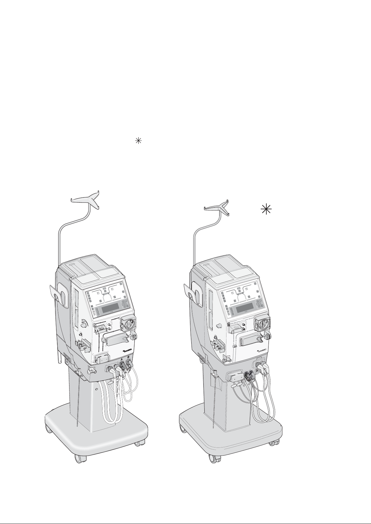
The exterior of the machine that you are using might be different in appearance from the
exterior described in this manual. If there is a difference, this is because you are using a
previous version of the machine.
Whenever this asterix symbol appears in the manual, it indicates that it is the previous
version of the machine.
The differences are to be found in chapter 2 and 4.
Machine in this manual Previous version of the machine
Page 2

Page 3

AK 96®Dialysis Machine
Operator's Manual
For use with program version 3.xx
Manufacturer:
Gambro Lundia AB
Box 10101
Magistratsvägen 16
SE-220 10 LUND
Sweden
Phone +46 46 169000
www.gambro.com
Questions or comments about this publication can be directed to your lo
Order number:
MHCEN12239–12/10
cal representative or to the manufacturer.
HCEN12239 Revision 12.2010
Program version 3.xx
Page 4

Intellectual Property Rights
Copyright:
© 2007, 2008-2009 G ambro Lundia AB. All rights reserved.
Trademarks:
AK 96®is a trademark of Gambro Lundia AB filed in the United S tates and registered in the European Community,
Australia, Bulgaria, Belarus, Switzerland, Ukraine, China, Croatia, Japan, South Korea, Morocco, Norway, Russian
Federation, Singapore, Syria and Turkey
®
BiCart
is a trademark registered in Austria, Bosnia-Herzegovina, Bulgaria, Benelux, Belarus, Czech Rep
Algeria, Egypt, Spain, France, Croatia, Hungary, Italy, North Korea, Kazakstan, Liechtenstein, Morocco, Monaco, The
former Yugoslav Republic of Macedonia, Mongolia, Portugal, Romania, Russian Federation, Sudan, Slovenia, Slovak
Republic, San Marino, Tunisia, Ukraine, Uzbekistan, Vietnam, Serbia and Montenegr
Finland, Mexico, New Zealand, Sweden, Uruguay, Japan, Greece, Australia, Brazil, Chile, Colombia, Denmark, Great
Britain, South Korea, Peru, Taiwan and the United States in the name of Gambro Hospal (Schweiz) AG, Gambro AB
and Gambro Lundia AB
CleanCart
Poland, Portugal, Romania, Russian Federation, Sudan, Slovenia, Slovak Republic, Albania, Armenia, Austria, Azerbaijan,
Bosnia-Herzegovina, Bulgaria, Benelux, Belarus, China, Cuba
Croatia, Hungary, Italy, Kyrgyzstan, North Korea, Kazakstan, Liech ten s tein , Liberia, Latvia, Morocco, Monaco, San
Marino, Tajikistan, Ukraine, Uzbekistan, Vietnam, Serbia and Montenegro, Canada, Japan, Sweden and Australia in the
name of Gambro Hospal (Schweiz) AG, Gambro AB and Gambro Lun
Diascan
Czech Republic, Germany, Greece, Croatia, Italy, Norway, Poland, Portugal, Russian Federation, Slovenia, Turkey,
Ukraine, Hong Kong, Mexico, Taiwan, United Stat
name of Gambro Hospal (Switzerland) ltd
U9000
The following trade m arks mentioned in the Op
Dialox
®
is a trademark registered in Switzerland, Moldova, The former Yugoslav Republic of Macedonia, Mongolia,
, Czech Republic, Germany, Algeria, Egypt, Spain, France,
dia AB
®
is a trademark registered in France, A ustria, Australia, Benelux, Switzerland, China, Serbia and Montenegro,
es and Great Britain in the name of Gambro Lundia AB and in the
®
is a tradema rk of Gambro Lundia AB re gistered in the European Community
erator’s Manual are not owned by any company within Gambro:
o, Switzerland, Argentina, Canada,
ublic, Germany,
Patents:
The AK 96 dialysis machine is protec
US: 5173125, 5792367, 5567320, 7246530, 7435235
EP: 745213, 658352
CA: 1327022, 2138354
DE: 69528156T2, 69406253, 69406257
ES: 2109643
FR: 9403710
JP: 3183528, 3618352
KR: 94404
SE: 524229
The AK 96 dialysis machine is protected by one or more of the following designs:
WO: DM/070849
EU: 000747811–00
AL: 420833801
AU: 318776 – 318782
CA: 123590
IN: 213741, 213742
KR: 497613
01 – 000747811–0007
ted by one or more of the following patents:
HCEN12239 Revision 12.2010
Program version 3.xx
Page 5

AK 96®Dialysis Machine
Operator's Manual
Program version 3.xx
Part 1 Base Manual for General Use
1. Before you get started - General Information
2. Description - The Machine and its Components
3. Operating the Machine - Handling Guidelines
4. Hemodialysis - Double Needle Treatment
5. Hemodialysis - Single Needle Treatment (option)
6. Isolated Ultrafiltration
7. Profiling
8. Hygiene and Maintenance
9. Technical Data and Specifications
10. Major Changes in Operator's Manual
Part 2 Instructions for Measurement Functions
11. BPM – Bloo
d Pressure Monitor (option)
12. Diascan® (option)
Part 3 Alarm Handbook
13. Alarms
14. Attention Alarms
Note
• Please observe that this part of the Operator's manual f or the AK 96 dialysis
machine is one out of three. To assimilate these instructions the complete
manual must be available. For information see “How To Use this Manual”
on page 1:2 in part 1.
Note
HCEN12239 Revision 12.2010
Program version 3.xx
Page 6

This page is intentionally left blank
HCEN12239 Revision 12.2010
Program version 3.xx
Page 7

Chapter 1
Before you get started - General
Information
Contents
HowToUsethisManual ..................................
How to findwhatyouarelookingfor ..................
ChapterDescriptions ...................................
Part1;BaseManualforGeneralUse ....................
Part2;InstructionsforMeasurementFunctions ............
Part3;AlarmHandbook ..............................
Definitions of Expressions used in this Manual . ..............
Warning ..........................................
Caution ...........................................
Note .............................................
OtherKeywordsusedinthisManual ....................
Figures .............................................
Symbols ............................................
SymbolswithinthisManual ...........................
SymbolswithintheUserInterface ......................
Symbols fixedontotheMachine .......................
GeneralPrecautionsbeforeuse ..............................
IntendedUse ...........................................
SafetyPhilosophy ........................................
The Preparation of Dialys
Inlet Water Requirement
Preparation of the Dia
UFD- Ultrafiltered Di
Ultrafilter - Frequ
List of Concentra
Concentrates
Lines ...............................................
Dialyzers
Blood Pre
Certific
ationmarks .......................................
tes,AccessoriesandDisposables ...............
.........................................
/Ultrafilter ....................................
ssureMeasurementAccessories ...................
isFluid ............................
s ...............................
lysisFluid ..........................
alysisFluid(option) ...................
encyofChange .......................
1:2
1:2
1:3
1:3
1:4
1:4
1:5
1:5
1:5
1:5
1:6
1:7
1:8
1:8
1:8
1:9
1:11
1:14
1:15
1:17
1:17
1:17
1:17
1:17
1:18
1:19
1:20
1:21
1:21
1:22
HCEN12239 Revision 12.2010
Program version 3.xx
AK 96®Operator's Manual - Before you get started
1:1
Page 8

How To Use this Manual
This Operator's Manual for the AK 96 dialysis machine is divided up
into three parts according to their contents. The reason for this is ease
of access for the operator of the machine. It is important to observe
that the parts should be considered as one document in spite of the
fact that it is printed in three separate parts. This means that things like
references and index extend over the complete manual. Furthermore,
note that all alarms and attention alarms are described in the third part,
the “Alarm Handbook”.
The first part; “Base Manual for General Use” include instructions on
how to generally use and run the m achine.
The second part; “Instructions for Measurement Functions” include
instructions on how to use the optional BPM (Blood Pressure Monitor)
and Diascan function.
The third part; “Alarm Handbook” include all alarms and attention
alarms originating from all functions of the machine.
The first part is printed in A 4 format, the second and third in A 5.
The parts are put in a box which should be considered as cover of the
complete manual. Conseqently, when the manual needs to be chang
to a m ore recent version due to updating of the machine program
version, the complete m anual (all three parts) needs to be changed at
the same time.
ed
How to find what you are looking for
To be able to find what you are looking for in this manual, first read the
brief explanation of how the chapters are structured and intended to be
used further on in this section. Then use the table of contents either
at the beginning of the complete manual or at the beginning of each
chapter. There is also an index included last in each part extending
over all three parts of the m anual.
References to pages within the manual are shown with two figures,
divided by a colon. The first figure is the chapter number and the
second is the page number. For example; page 4:10 would be chapter
4, page 10. The first page in all three parts is the same, i.e. an overview
of which chapter numbers are included in which part.
A small reference number beside the figures within the manual has
been added to simplify manual production.
On the following pages is a brief explanation of how the parts and
chapters in this manual are structured and are intended to be used.
1:2
AK 96
®
Operator's Manual - Before you get started
HCEN12239 Revision 12.2010
Program version 3.xx
Page 9

Chapter Descriptions
Part 1; Base Manual for General Use
Chapter 1; Before you get started - General Information
This chapter contains information to be read before using the
AK 96 dialysis machine.
Chapter 2; Description - The Machine and its Components
This chapter contains component descriptions (terms and details) of the
blood part, the fluid part and the rear of the machine.
Chapter 3; Operating the Machine - Handling Guidelines
This chapter contains explanations of how the machine is to be
controlled. For example, how to use the buttons and the keypad of the
Operator's panel together with the menus on the Information Display.
Furthermore in this chapter, the alarm functions are described and how
parameters are to be set. How to use handling features of the machine
are also explained here. The overview screens displayed on the
Information Display are explained as well as the ultrafiltration control,
and information is provided on what to do if a power failure occurs.
Chapter 4; Hemodialysis - Double Needle Treatment
This chapter contains instructions on how to p
erform hemodialysis
with two needles, using the AK 96 dialysis machine. The chapter
begins with how to start the machine and continues with how to attach
the dialyzer and the blood lines, the prim
ing procedure, starting the
treatment and setting of parameters. It finishes with the discontinuing
procedure.
Chapter 5; Hemodialysis - Single Needle Treatment (option)
This chapter contains instructions on how to perform hemodialysis
with one needle. The chapter is based on chapter 4 "Hemodialysis Double Needle Treatment" starting on page 4:1 in part 1, with added
specific instructions for single needle treatment.
Chapter 6; Isolated Ultrafiltration
This chapter contains instructions on how to perform isolated
ultrafiltration.
Chapter 7; Profiling
This chapter contains instructions on how to use the profiling function
for ultrafiltration, as well as for the dialysis fluid concentration of
sodium and bicarbonate.
HCEN12239 Revision 12.2010
Program version 3.xx
Chapter 8; Hygiene and Maintenance
This chapter contains information and instructions concerning the
hygiene
and maintenance of the machine that should be carried out
by the operator of the machine. The chapter begins with a general
section where a schedule for hygiene and maintenance is included.
The H
ygiene sections contain general information and instructions
on how to perform the disinfection programs. The Maintenance
sections include instructions on the maintenance of the flow path and
e e xterior of the machine.
th
AK 96®Operator's Manual - Before you get started
1:3
Page 10

Chapter 9; Technical Data and Specifications
This chapter contains technical specifications of the control and
supervisory systems of the machine. It also includes physical data,
materials which come into contact with water, concentrates and dialysis
fluid, environmental data and a list of standards which the machine
complies with.
Chapter 10; Major changes in operator's manual
This chapter includes brief information about major changes
between the current and previous program versions of the machine
that have been made in the manual. The changes mentioned are
mostly information concerning the operation of the machine and are
specifically addressed to the operator.
Part 2; Instructions for Measurement Functions
Chapter 11; BPM – Blood Pressure Monitor (option)
This chapter contains instructions on how to use the BPM (if installed),
which measures blood pressure and pulse rate. A particular bloo
d
pressure measurement cuff and a cuff hose are to be used. The
chapter includes explanations of how the BPM is handled using t he
BPM button and the BPM screens, and also describes the alarm
function. The BPM can be used manually if only one measurement
check is to be done, or at set intervals during treatment.
Chapter 12; Diascan®function (option)
This chapter contains instructions on how to use the Diascan function,
which m easures clearance (K) and dialysis dose (Kt or Kt/V). The
chapter is divided into two parts where the first section includes
general information about the Diascan function, explanation of the
Diascan screens and the alarm functions. The second section includes
step-by-step instructions for measuring clearance and Kt/V, single or
continuous measuring.
Part 3; Alarm Handbook
Chapter 13; Alarms
This chapter contains a list of alarms. The list includes additional
information concerning possible causes and suggestions about
measures to be taken f
Chapter 14; Attention Alarms
or each alarm.
This chapter contains a list of attention a larms. The list includes
additional information concerning possible causes and suggestions
about measures to be taken for each attention alarm. The attention
alarms in the list is shown in alphabetical order.
1:4
AK 96
®
Operator's Manual - Before you get started
HCEN12239 Revision 12.2010
Program version 3.xx
Page 11

Definitions of Expressions used in this Manual
Warning
WARNING
Is used to alert the user/operator not to take a certain action, which
if taken can cause a potential hazard and result in a serious adverse
reaction, injury or death. A warning may also be used to alert the
user/operator to take a certain action to avoid the potential hazard
as above.
Caution
CAUTION
Is used to alert the user/operator to take a certain action to protect
against a possible hazard which, if ignored, could have an adverse
effect on the patient or the equipment. A caution may also be us
to alert the user/operator not to take a certain action to avoid the
potential hazard as above.
WARNING
ed
CAUTION
Note
Note
• A reminder to the user/operator on normal treatment activity
and on what is a suitable action in a particular situation.
Note
HCEN12239 Revision 12.2010
Program version 3.xx
AK 96®Operator's Manual - Before you get started
1:5
Page 12

Other Keywords used in this Manual
User
A User in this manual, designates a person who has the comprehensive
responsibility for how the AK 96 dialysis machine is being used. The
user decides which clinic routines are applicable for the AK 96 dialysis
machine.
Operator
An Operator in this manual, designates a person who has knowledge of
and has been trained in hemodialysis and is in charge of the machine
i.e. makes the machine settings which have to be done before, during
and after the hemodialysis treatment. The operator is sometimes
referred to as ”You”.
Authorized technician
The Authorized technician is a technician who has been through
Gambro training on the AK 96 dialysis machine and has received a
Gambro certificate or has gained equivalent knowledge in some other
way.
Machine
Whenever the word Machine is used within this manual, machine
always refers to the AK 96 dialysis machine if no other is written.
Manual
Whenever the word Manual is used within this m anual, manual always
refers to this Operator's Manual for the AK 96 dialysis machine if no
other is written.
Option
Sometimes functions and machine compone
nts are marked Option,
meaning that the machine may not be equipped with the described
function/component. Sometimes the option is a function/component
of which the machine has been manufactu
redwithandsometimesthe
option can be implemented by an authorized technician afterwards
upon request.
1:6
AK 96
®
Operator's Manual - Before you get started
HCEN12239 Revision 12.2010
Program version 3.xx
Page 13
Figures
There are different type of figures included in this manual. Screens and
menus shown on the Information Display are one type of figure. These
figures are a direct "shot" of the Information Display of the machine
and have not been revised afterwards in order for the operator to
recognize current machine displays for the ongoing procedure. Some
figures illustrate handling or point out components of the machine.
To highlight certain items or illustrate movements arrows have been
included in these figures.
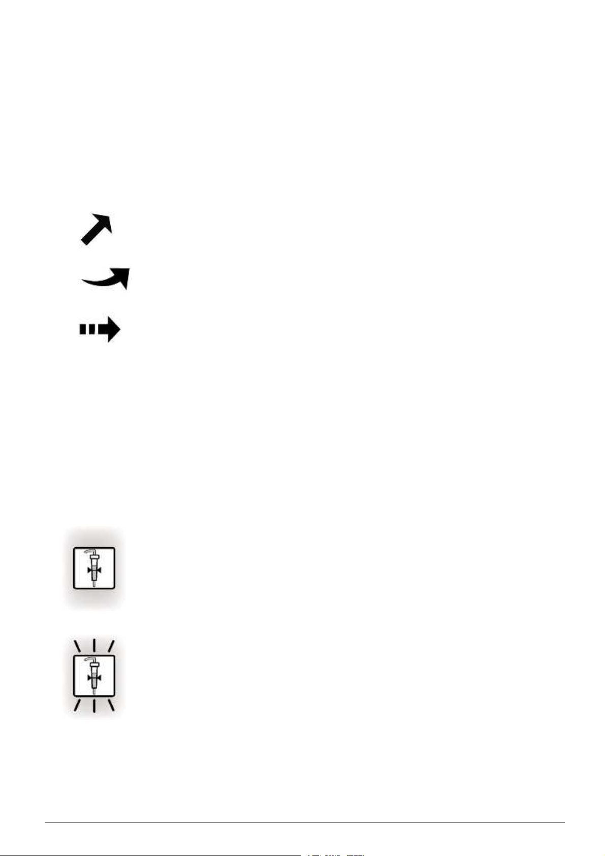
This "straight arrow" in figures points out details described in the
corresponding text. The arrow can also show a direction, i.e. if
somethingistobemovedinacertaindirection.
This "curved arrow" i n figures shows a direction of a rotation. This can
be the direction of something that is to be connected or opened/closed.
This "pressure arrow" appears in figures when something is to be
pressed in or pulled out. The point where the arrow points to is the
pressure/pulling point.
In addition, to highlight certain items, the details that the describing
text in the instructions aims at, are highlighted in gray in the
corresponding figure.
The buttons on the operator's panel light up in different situations to
guide the operator or to inform of current status. If the button is lit or
not is not normally illustrated in the handling instructions; the button
figures are the same for lit, flashing and not lit buttons. This is valid
for all instructions except for the alarm list (see "Alarm List" on page
13:9 in part 3) where the button figures also show status in order for
the operator to apprehend the instructions fully.
This is an example of a lit button.
This is an example of a flashing button.
HCEN12239 Revision 12.2010
Program version 3.xx
A small reference number beside the figure has sometimes been added
to simplify manu
al production.
AK 96®Operator's Manual - Before you get started
1:7
Page 14

Symbols
Symbols within this Manual
When this symbol appears in the manual text, it indicates that it is
possible to preset the value of a parameter. The preset can be done to
adapt the settings of the m achine to correspond with the routines of the
user/clinic. It has to be done by an authorized technician.
All values mentioned in this manual are default values set in the
machine when it was manufactured. It is important to check with the
authorized technician if values have been changed, and if so, which
ones.
For instance, it is possible to preset the machine for which mode to
start up in, some alarm limits, some functions and options.
This symbol appears at the right hand side of a page when there is more
important information to be read on the following page (there is not
enough room for all assembled information on the same page). Please
continue your reading to obtain the complete information.
In lists, different icons in front of the items show how the lists are
to be used.
1. A numbered list is to be followed from the beginning to the end.
This kind of list mostly appears in handling
instructions.
• In a bullet list not all items may be valid and the items in the list
are not presented in a particular order.
A checkbox list is used when a number of items should be checked
before a procedure is perform
ed.
- In a dashed list all items are valid but are not presented in a
particular order.
Symbols within the User Interface
See chapter 3, "Buttons" starting on page 3:8 in part 1.
1:8
AK 96
®
Operator's Manual - Before you get started
HCEN12239 Revision 12.2010
Program version 3.xx
Page 15
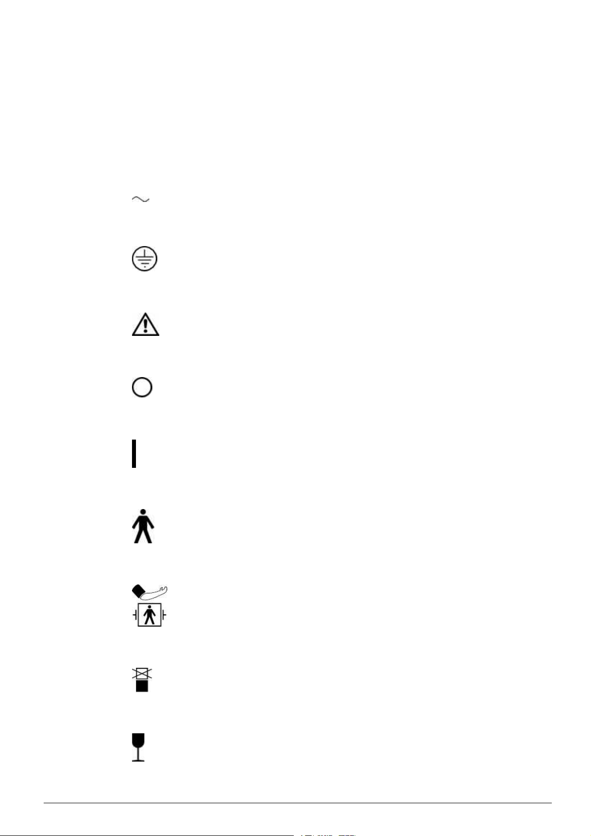
SymbolsfixedontotheMachine
All symbols in the list below may not be represented on this product.
The symbols can be attached to the machine or attached to the original
packaging.
Symbol Description
Alternating c urrent
Protective earth (ground)
Warning, consult accompanying
documents
Off (power, disconnection from the
mains)
On (power, connection to the mains)
Type B, applied part
NIBP type BF applied part, defibrillator
proof
HCEN12239 Revision 12.2010
Program version 3.xx
Do not stack
Fragile – Handle with care
AK 96®Operator's Manual - Before you get started
1:9
Page 16
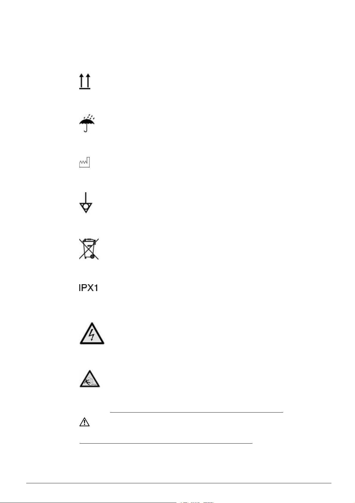
Symbol Description
This way up
Keep dry
Year of manufacturing
Equipotentiality
Separate collection for electrical and
electronic equipment
The AK 96 dialysis machine is protected
against dripping water
Warning, Dangerous voltage. Contact
may cause electric shock or burn.
The label is yellow with a black frame
and icon. This symbol is a warning label
not to tilt the machine through an angle
of more than 5°.
WARNING
If a remote operator's panel has been installed, fluid bags must
be removed from the in
transporting (moving) the machine.
fusion pole or placed on the top tray when
WARNING
1:10
AK 96
®
Operator's Manual - Before you get started
HCEN12239 Revision 12.2010
Program version 3.xx
Page 17

General Precautions before use
WARNING
Unauthorized modifications, alterations or repair and lack of
maintenance or calibration of the AK 96 dialysis machine may result
in malfunctioning or have other serious consequences for the safe
operation of the equipment.
CAUTION
The AK 96 dialysis machine may only be operated by persons
trained in hemodialysis and who have studied the instructions in this
manual. The user/operator should draw special attention towards
the text valid for the safety philosophy of the machine. See section
"Safety Philosophy" on page 1:15 in part 1. Verify that the first digit
of the program version of both the machine and the manual is the
same. If the AK 96 dialysis machine does not perform as described
in this manual, it should not be used until the condition is rectified.
When unpacking, check the equipment for any signs of damage.
If the equipment is in any way damaged, proper operation cannot
be assured.
WARNING
Patients connected to the AK 96 dialysis machine should be
monitored by competent personnel since life thr
can arise that may not activate alarms. The operator should pay
attention to all appropriate alarms and follow the instructions,
warnings, cautions, and notes given in this
that the machine has passed the function check before connecting
to a patient.
During installation all calibration checks must be completed before
the machine is used for dialysis treatment.
The AK 96 dialysis machine needs special precautions regarding
EMC and needs to be installed and put into service according to
the EMC information provided
Data and Specifications".
The use of mobile teleph
vicinity of the AK 96 dialysis machine could adversely influence the
performance of the machine. For further information, see part 1 and
chapter 9, "Technica
The AK 96 dialysis machine will perform as designed only if it is
used and maintai
Any warranties made by Gambro with respect to the AK 96 dialysis
machine are void if the equipment is not used in accordance with
the instructi
any damage or injury resulting from improper use or maintenance
or unauthorized repair.
ons provided. Gambro will not accept responsibility for
l Data and Specifications".
ned in accordance with Gambro’s instructions.
in part 1and chapter 9, "Technical
ones or communication equipment in the
eatening situations
manual. It is imperative
CAUTION →
→→
HCEN12239 Revision 12.2010
Program version 3.xx
AK 96®Operator's Manual - Before you get started
1:11
Page 18

→→→CAUTION
Preventive inspection, maintenance and calibration of the
AK 96 dialysis machine shall be performed by a fully trained
authorized service technician according to the Maintenance Manual
in the AK 96 Service Manual which can be ordered from your
Gambro representative. It is mandatory for preventive maintenance
to be performed at least every other year. Yearly maintenance
is recommended. The interval between preventive maintenance
procedures might differ due to operating environment variations.
The AK 96 dialysis machine is in compliance with certain
requirements concerning patient leakage current from the dialysis
fluid in accordance with international standards and regulations.
When a central venous catheter is used, and the tip of the
catheter is close to the heart, it is however necessary to take
extra precautions to minimize the risk of arrythmia due to leakage
currents. For these treatments it is necessary to connect the
potential equalization conductor between the AK 96 dialysis
machine and the potential equalization bus bar in the electrical
installation. Potential equalisation also has to be used when legal
requirements of the installation place requires it.
To minimize the leakage currents from other electrical equipment it
is recommended to place such equipment outside the patient area.
Any equipment within the patient area shall fulfil the IEC 60601-1
and IEC 60601-1-1 standards and be a part of the potential
equalization. One way to minimize the leakage currents from
equipment within the patient area is to electrically isolate it. Make
sure leakage current values are below respective limit required by
CF type applied parts. Check with authorized technician.
If your clinic/hospital uses a central venous catheter during
treatments please make sure your machine is equipped with a
potential equalization connection. If not please contact your local
Gambro Service Technician for further assistance.
The AK 96 dialysis machine is not suitable for use in the presence
of a flammable anesthetic mixture with air or with oxygen or nitrous
oxide.
CAUTION
1:12
AK 96
®
Operator's Manual - Before you get started
HCEN12239 Revision 12.2010
Program version 3.xx
Page 19

Note
• This Operator’s Manual provides instructions necessary for the
proper operation of the AK 96 dialysis machine. It is not a
guide for the administration of hemodialysis.
• Machines are not disinfected before delivery. Always perform
a chemical disinfection after installation, before initial use.
• When accuracy ranges are written as e.g. ”(±1 ml/min or
±1%)” the widest range is valid.
• During transportation and storage the equipment has to be kept
in its original packing. If transportation or storage time is more
than 15 weeks the environmental data relating to the operation
has to be followed.
• For the authorized technician the Service Manual for the
AK 96 dialysis machine is available. The Service Manual
provides all of the necessary information for installation and
safe and required maintenance of the machine.
• It is important that the protective earth in the installation i
high quality.
• For the purpose of protecting the environment the
AK 96 dialysis machine must not be disposed of with
general domestic waste, but shall be separately collected
for dismantling and recovery. Where applicable
, national
regulations shall be applied. Consult your local Gambro
distributor for information.
• The AK 96 dialysis machine is intended for continuous
operation.
sof
Note
HCEN12239 Revision 12.2010
Program version 3.xx
AK 96®Operator's Manual - Before you get started
1:13
Page 20

Intended Use
TheGambroAK96dialysismachineisdesignedtobeusedasa
single patient machine to perform hemodialysis treatments upon
prescription by a physician. Patient counselling and teaching of
treatment techniques are directly under the supervision and discretion
of the physician.
CAUTION
Patient education, counselling, home care follow-up and medical
maintenance must be performed under the direction and supervision
of the physician prescribing the treatment. Gambro specifically
denies any responsibility for patient education, counselling or home
care and medical maintenance.
When the AK 96 dialysis machine is used to produce bicarbonate
containing dialysis fluid originating from non-liquid concentrates, the
AK 96 dialysis machine is designed and validated for use with the
Gambro BiCart cartridge. Gambro does not accept responsibility for
use of other non-liquid concentrate containers.
CAUTION
1:14
AK 96
®
Operator's Manual - Before you get started
HCEN12239 Revision 12.2010
Program version 3.xx
Page 21

Safety Philosophy
The AK 96 dialysis machine is designed according to the current
standards for hemodialysis equipment, IEC 60601-2-16. This means
that safety under so-called Single Fault Conditions is granted. In
practice this means that controllable treatment parameters (i.e.
conductivity, temperature and ultrafiltration) are controlled by one
system, the control system, and monitored by another completely
separate protective system, utilizing its own sensors, electrical circuits
and m icroprocessors. The functionality of the protective system is
checked by the AK 96 dialysis machine before each treatment. A fault
detection during the pre-treatment tests will make it impossible to
start the treatment.
In order to verify that the corresponding control and protective systems
are operating with the correct input values, the user is instructed to
compare the readings from these systems before connecting to the
patient. Check that the calculated conductivity values (C/P) displayed
in the conductivity menu are in agreement. If this comparison is not
satisfactory, call an authorized technician.
The protective system will, when a parameter (measured by the
protective system) is outside the alarm limits, put the AK 96 dialysis
machine into a patient-safe condition. This means that the
system can stop the blood pump, close the venous clamp, prevent the
dialysis fluid from reaching the dialyzer and alert the operator with
sound and light.
protective
There is a risk that the b lood of the patient may be contaminated
with bacteria and endotoxins due to transpor
t of undesired substances
from the dialysis fluid compartment to the blood compartment of the
dialyzer. This risk is reduced by using intact dialyzers, high inlet
water quality, high quality of conce
ntrates and by using the optional
ultrafilter for dialysis fluid.
Ultrafiltration
For the ultrafiltration control system, the transmembrane pressure
(TMP) is used as the protective system. Alarm limits for TMP related
to the dialyzer UF coefficient and the expected UF rate, are to be set
around the actual TMP value when starting treatment. The TMP alarm
limit correspond to a UF-deviation limit described by TMP
UF
coefficient
. Example: If the alarm window is set to ±50 mmHg and
Alarm limit
x
the UF-coefficientis10ml/mmHgxhthemaximumweightdeviations
without any alarm is ±500 g/h. Default the alarm window is set to
±100 mmHg. It is essential to ensure that the alarm window is set as
close as possible to the working TMP. As an additional precaution it is
recommended that the blood pressure is checked regularly.
HCEN12239 Revision 12.2010
Program version 3.xx
Venous pre
ssure
To protect the patient against a hazardous blood loss to the environment
AK 96 dialysis machine incorporates a venous pressure monitoring
system
. This system will react on a change in the venous pressure,
AK 96®Operator's Manual - Before you get started
1:15
Page 22

i.e. when the pressure falls below the low alarm limit. It must be
observed that under certain pressure/ flow conditions a blood loss to
the environment may not be able to cause the venous pressure to fall
below the low alarm limit. To avoid blood loss to the environment
it is essential to ensure that all connections in the extracorporeal
blood circuit are tight and secured, that the fistula needle is correctly
positioned and secured and that the low alarm limit is set as close as
possible to the working venous pressure.
The venous pressure measuring system is the protection against blood
loss to the environment. This measuring system is automatically
checked before each treatment. A failure will make it impossible to
start the treatment.
Blood pump
The supervision of the stop time of the blood pump is the protection
system against patient blood loss due to coagulation during treatment.
The operator will be notified via an attention alarm that the blood pump
stop time has been exceeded.
Blood leak detector
The blood leak detector system, which utilizes an optical sensor, is
automatically tested before each treatment for
being a ble to detect
transparency (no blood) and non-transparency (blood) before each
treatment. If the system cannot detect these states, it is impossible to
start the treatment.
Air detector
The air detector utilizes an ultrasonic sound sensing system in which
the transmitter is handled by one microprocessor and the receiver is
handled by both microprocessors in the protective system. The system
is tested pre-treatment for parameter deviation in terms of sensitivity
change.
Any infusion/transfusion/medication given to the patient via the
extracorporeal blood circuit of the AK 96 dialysis machine during
treatment, must pass the venous drip chamber and the activated air
detector. I nstructions for infusions can be read in "Infusions during
Treatment" on page 3:36 in part 1.
1:16
Chemical disinfectant intake
The AK 96 dial
ysis machine is designed to take in chemical
disinfectants via a permanent connection. For this reason, the machine
is equipped with an extra valve within the protective system. The
machine au
tomatically checks before each treatment if a chemical
disinfection program has previously been performed and if so, the
chemical intake valves are automatically checked during function
check. A
failure will make it impossible to start the treatment.
®
AK 96
Operator's Manual - Before you get started
HCEN12239 Revision 12.2010
Program version 3.xx
Page 23

The Preparation of Dialysis Fluid
Inlet Water Requirements
The chemical and microbiological quality of the water used to prepare
fluids for dialysis is a n important factor for achieving and maintaining
the proper quality of the d ialysis fluid.
The quality of the water depends on the technical equipment for water
treatment. Further, proper maintenance of the water treatment system
and of the water distribution loop is essential.
The inlet water must comply with valid standards for water for dialysis;
see "Water supply" on page 9:11 in part 1 for more details.
Preparation of the Dialysis Fluid
The AK 96 dialysis machine prepares dialysis fluid f rom inlet water
and concentrates.
The dialysis fluid should be made from an acidic (A) concentrate and a
dry bicarbonate concentrate (such as the BiCart cartridge). It can also
be made from an acidic (A) concentrate and a liquid
concentrate or from an acetate concentrate. See "Concentrates" on
page 1:19 in part 1.
bicarbonate (B)
UFD- Ultrafiltered Dialysis Fluid (option)
The AK 96 dialysis machine can be equipped with a holder in which
an ultrafilter can be mounted. The ultrafilter purifies the dialysis fluid
from possible contamination by bacteria and endotoxins.
Ultrafilter - Frequency of Change
The ultrafilter used when
be changed regularly depending on the primary fluid quality and the
desired final fluid quality. The results from microbiological controls
have to determine the
a month and once every three months can be expected.
For instructions
on how to change the ultrafilter, see “Ultrafilter - How
tochange"onpage8:39inpart1.
preparing Ultra Filtered Dialysis Fluid is to
frequency of change. A frequency between once
HCEN12239 Revision 12.2010
Program version 3.xx
AK 96®Operator's Manual - Before you get started
1:17
Page 24

List of Concentrates, Accessories and
Disposables
This manual contains a number of r eferences to concentrates,
accessories and disposables for use with the AK 96 dialysis machine.
For ease of reference, set out below i s a comprehensive listing of such
concentrates, accessories and disposables as follows.
CAUTION
The AK 96 dialysis machine has been tested and validated for
use with the concentrates, accessories and disposables specified
as follows.
Gambro does not accept any responsibility or liability for use of
concentrates, accessories or disposables other than those specified
as follows. Depending on the circumstances, use of concentrates,
accessories or disposables other than those specified may also
reduce Gambro’s warranties for the AK 96 dialysis machine.
Observe the manufacturer's instructions for use regarding single
use of blood lines and dialyzers.
CAUTION
Note
• The user should make sure to have a current listing of
concentrates, accessories and disposables available.
• The user should follow the facility procedures for proper
disposal of used blood lines, dialyzers and other disposables
per local regulations.
Note
1:18
AK 96
®
Operator's Manual - Before you get started
HCEN12239 Revision 12.2010
Program version 3.xx
Page 25

Concentrates
CAUTION
Incorrect choice of dialysis fluid concentrate may cause incorrect
composition of the dialysis fluid. Incorrect composition may lead to
electrolytic imbalance in the patient's blood.
Liquid concentrates Area of use
001-099 series Liquid acetate concentrates for
preparation of acetate dialysis fluid.
CAUTION
2xx series
7xx series
8xx series
Liquid A-concentrate for preparation of
bicarbonate dialysis fluid together with
BiCart cartridge or with bicarbonate
hemodialysis concentrate D 200 (Sodium
bicarbonate 8,4%).
3xx series Liquid A and B concentrates for
preparation of bicarbonate dialysis fluid.
Non-liquid concentrates Area of use
®
BiCart
cartridge Dry bicarbonate concentrate for
preparation of bicarbonate dialysis
fluid together with proper liquid
A-concentrate.
HCEN12239 Revision 12.2010
Program version 3.xx
AK 96®Operator's Manual - Before you get started
1:19
Page 26

Lines
Line number Area of use
Gambro Medical Line (PVC+DOP/ EtO sterilized)
BL 10 series Arterial and venous blood line set
BL 100 series Arterial and venous blood line set
AV 100 series Arterial and venous blood line set
A 5000 series Arterial blood lines
Note especially the Warning text below
concerning pediatric blood line set
V 5000 series Venous blood lines
Note especially the Warning text below
concerning pediatric blood line set
Gambro Blood Tubing System (PVC+DOA/Beta sterilized)
BL 200 series Arterial and venous blood line set
Gambro Accessories
C series Hemodialysis accessories
C 705
A connection line with an expansion
chamber. Used in single needle mode.
WARNING
Do not use the pediatric blood lines; A-5.128-B4 or V-5.127-X. The
blood line clamps of the AK 96 dialysis machine cannot clamp these
thin blood lines.
WARNING
1:20
AK 96
®
Operator's Manual - Before you get started
HCEN12239 Revision 12.2010
Program version 3.xx
Page 27

Dialyzers/Ultrafilter
Dialyzer/Ultrafilter Area of use
U9000
®
Ultrafilter used when preparing Ultra
Filtered Dialysis Fluid.
Dialyzers Most types of dialyzers, except plate
dialyzers, can be used. However, it is
essential to verify that the specifications
and instructions for use of the dialyzers
are not in discrepancy with those given
for AK 96 dialysis machine, with regards
to e.g. the maximum UF coefficient and
the recommended priming procedure.
The connectors and the ports of the
dialyzer must comply with ISO 8637 and
EN 1283.
Blood Pressure Measurement Accessories
Gambro Cuff Size
Adult
Large Adult
Small Adult
Child
Gambro Cuff
(single hand)
Adult
Large Adult
Small Adult
Gambro Cuff hose)
3.0 m
23 - 33 cm
31 - 40 cm
17- 25 cm
12 - 19 cm
Size
28 - 37 cm
36 - 46 cm
21 - 29 cm
Cuff hose used for measuring blood
pressure together with the AK 96 dialysis
machine.
HCEN12239 Revision 12.2010
Program version 3.xx
AK 96®Operator's Manual - Before you get started
1:21
Page 28

Certification marks
CE-marking
The CE-conformity mark indicates that the AK 96 dialysis machine
conforms to the requirements in the EC Council Directive 93/42/EEC
of 14 June, 1993 concerning medical devices. It also indicates that
the notified body British Standards Institution (BSI, No. 0086) has
approved the Quality Management System. The CE conformity mark
is only valid for the AK 96 dialysis machine. Disposables and any
accessories specified for use with the AK 96 dialysis machine are
marked with CE conformity marks in their own right.
CSA-marking
The CSA mark indicates that the AK 96 dialysis machine
conforms to
the requirements related to safety of medical devices for Canada and
that the AK 96 dialysis machine has been evaluated to the applicable
CSA standards for use in Canada.
CCC-marking
The CCC mark indicates that the AK 96 dialysis machine conforms to
the safety requirements for China Compulsory Certification (CCC) as
described by the competent authority Certi fication and Accreditation
Administration of People’s Republic of China (CNCA). The “S”
adjacent to the CCC mark indicates that safety requirements are met.
1:22
AK 96
®
Operator's Manual - Before you get started
HCEN12239 Revision 12.2010
Program version 3.xx
Page 29

Chapter 2
Description - The Machine and its
Components
Contents
TheBloodPartoftheMachine ..............................
BloodPartComponentTerms ............................
BloodPartComponentDetails ...........................
TheFluidPartoftheMachine ..............................
FluidPartComponentTerms .............................
FluidPartComponentDetails ............................
TheRearoftheMachine ..................................
RearComponentTerms .................................
RearComponentDetails ................................
2:2
2:3
2:5
2:16
2:17
2:19
2:28
2:29
2:31
HCEN12239 Revision 12.2010
Program version 3.xx
AK 96®Operator's Manual - Machine Description
2:1
Page 30
The Blood Part of the Machine
2:2
AK 96
®
Operator's Manual - Machine Description
HCEN12239 Revision 12.2010
Program version 3.xx
Page 31
Blood Part Component Terms
The list below shows positions and terms, for the components pointed
out in the overview picture of the blood part of the machine (see figure
on the previous page). A detailed description where each component
is described separately, sometimes with informative text included,
follows next in this section.
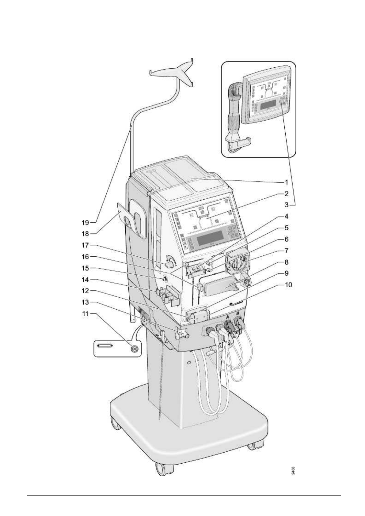
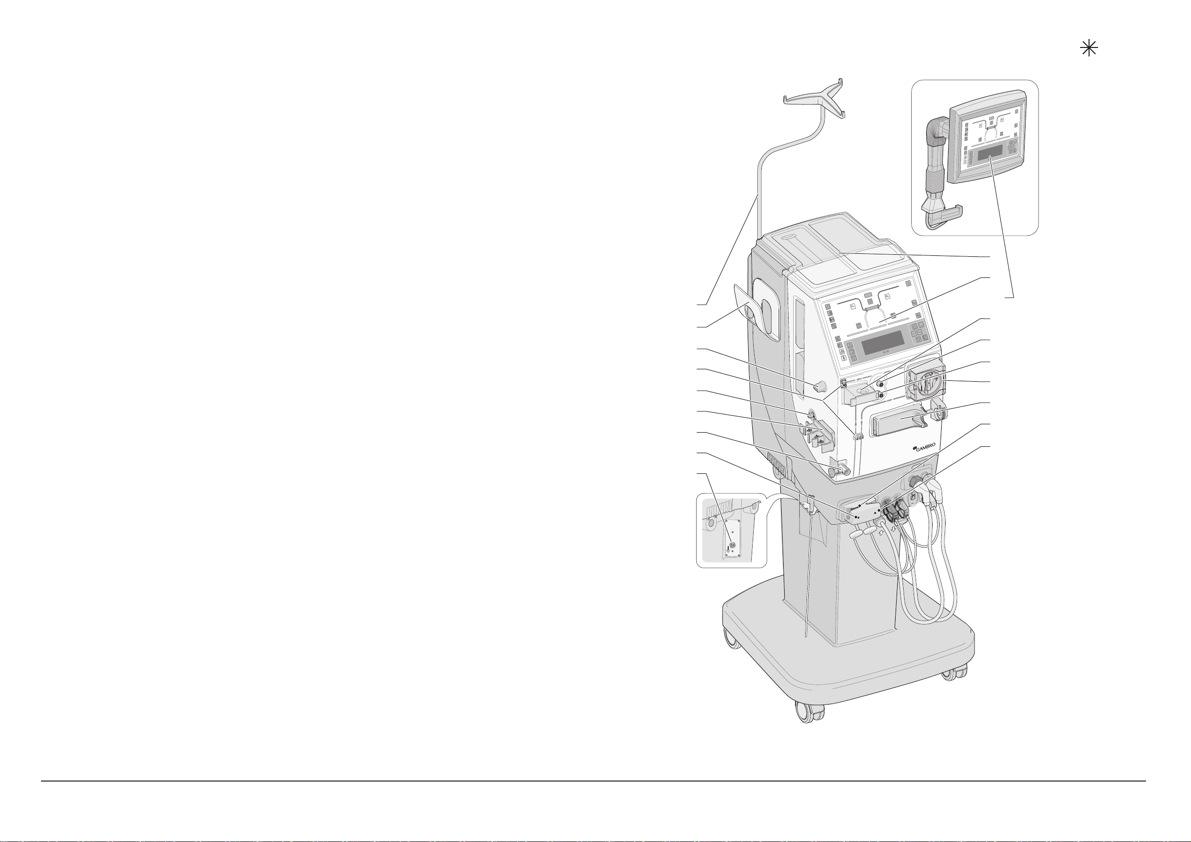
1. Top Tray
2. Operator's Panel
3. Remote Operator's Panel (option)
The Blood Part of the Machine
4. Air Detector
5. Venous Pressure Transducer Connector
6. Arterial Pressure Transducer Connector
7. Blood Pump
8. Heparin Pump (option)
9. Priming Detector
10. Arterial Blood Line Clamp (option)
11. Potential Equalization Connection
12. Venous Blood Line Clamp
13. Arm for Dialyzer Holder
14. Expansion Chamber Holder
19
18
17
16
15
14
13
12
11
1
2
3
4
5
6
7
8
9
10
HCEN12239 Revision 12.2010
Program version 3.xx
15. BPM Connector (option)
16. Blood Line Guides
17. Level Adjustment Knob
18. BPM Cuff Holder (option)
19. Infusion Pole
®
AK 96 Operator's Manual - Machine Description
2502
2:3
Page 32

Blood Part Component Details
1. Top Tra y
To protect the machine against spillage, the top tray must
always be correctly placed on top of the machine.
2. Operator's Panel
The parts of the operator's panel are described in "The
Operators Panel" on page 3:6 in part 1.
3. Remote Operator's Panel (option)
The operator´s panel can be mount
This Remote Panel is easy to adjust in different positions.
The handling procedures are the same as for the usual
operator's panel.
WARNING
If a remote operator's panel has been installed, fluid bags must
be removed from the infusion pole or placed on the top tray
when trans
porting (moving) the machine.
ed in an external housing.
WARNING
HCEN12239 Revision 12.2010
Program version 3.xx
AK 96®Operator's Manual - Machine Description
2:5
Page 33

4. Air Detector
The ultrasonic air detector will detect air or foam in the
venous drip chamber.
The air detector cover may be opened with ease by
pressing the middle of the cover at the same time as the
cover is being opened, as shown in the corresponding figure.
The air detector head is designed for a drip chamber with a
diameter of 22 mm. Instructions on
how to attach the venous
drip chamber of the venous blood line in the air detector,
can be read in "Venous Blood Line - Attach" on page 4:28
in part 1.
2:6
AK 96
®
Operator's Manual - Machine Description
HCEN12239 Revision 12.2010
Program version 3.xx
Page 34

5. Venous Pressure Transducer Connector
The pressure in the venous drip chamber is measured when
the venous pressure transducer of the venous blood line is
attached properly to this connector. Instructions on this can
be read in "Venous Blood Line - Attach" on page 4:28 in
part 1.
6. Arterial Pressure Transducer Connector
The pressure in the arterial blood line, just before the blood
pump, is measured when the arterial pressure transducer of
the arterial blood line is attached properly to this connector.
Instructions on this can be read in "Arterial Blood Line Attach" on page 4:16 in part 1.
HCEN12239 Revision 12.2010
Program version 3.xx
AK 96®Operator's Manual - Machine Description
2:7
Page 35

7. Blood Pump
The blood pump parts are:
a) the Pump Housing
b)thePumpShaft
c) the Pump Cover
d) the Pump Rotor and
e) the Pump Handle
as shown in the corresponding figure.
The blood flow measuring of the AK 96 dialysis machine
is based on blood pump rotations (see also in "Blood Flow
Control" on page 9:2 in part 1).
If the blood pump cover is opened whilst the blood pump is
running, it will stop until the cover is closed again.
During a power failure the pump can be manually operated
by turning the pump rotor in an anticlockwise direction,
using the pump handle.
The pump cover may be opened with ease by pressing the
middle of the cover at the same time as the cover is being
opened, as shown in the corresponding figure.
2:8
AK 96
®
Operator's Manual - Machine Description
HCEN12239 Revision 12.2010
Program version 3.xx
Page 36

To remove the blood pump rotor; hold the handle and pull
out. Then turn clockwise until the blood pump rotor loosens
from the pump shaft.
To attach the blood pump rotor; whilst holding the handle,
place the rotor on the pump shaft. Then move your fingers
from the handle and place them on the rotor as shown in the
figure. Turn the rotor clockwise slowly, and at the same time
push slightly, until it reaches the bottom position. Continue
turning until the blood pump handle clicks in.
HCEN12239 Revision 12.2010
Program version 3.xx
AK 96®Operator's Manual - Machine Description
2:9
Page 37

8. Heparin Pump (option)
The Heparin pump can be programmed for different syringe
sizes
. Syringes must comply with ISO 7886-2.
Instructions on how to attach the syringe to the pump, and
how to do the heparin pump settings, can be read in "Arterial
Blood Line - Attach" starting on page 4:16 in part 1, see
point 8.
9. Priming Detector
The priming detector detects if there is blood in the venous
blood line. When blood has been detected, treatment alarms
are activated. T herefore, it is of the utmost importance that
the venous blood line is correctly placed in the priming
detector before treatment is started, see "Venous Blood Line
- Attach" starting on page 4:28 in part 1, see point 5 for
instructions on this.
Before the priming detector detects blood certain alarms are
suppressed to facilitate the priming procedure. When blood
has been detected, the treatment time starts to count down
and accumulated treatment parameter values will start to be
measured and displayed. The treatment time will continue to
count down as long as blood is detected.
2:10
AK 96
®
Operator's Manual - Machine Description
HCEN12239 Revision 12.2010
Program version 3.xx
Page 38

10. Arterial Blood Line Clamp (option)
The arterial blood line clamp closes the arterial blood line
in certain alarm situations during treatment. It is also of
great importance when performing single needle treatment,
as it is closed during the venous phase of the single needle
cycle. This is to minimize recirculation. See "General"
and "Glossary of single needle parameters and key terms"
in the introductory parts of chapter 5 in part 1 for further
information.
11. Potential Equalization Connection
This connection is used for the potential equalization
conductor. When a central venous catheter is used, the
conductor must be connected to minimize the risk of electric
shock. The connection is marked with the symbol for
equipotentiality (see "Symbols fixedontotheMachine“
starting on page 1:9 in part 1).
12. Venous Blood Line Clamp
The venous blood line clamp closes the venous blood line
in certain alarm situations during t
reatment. It is also of
great importance when performing single needle treatment,
as it is closed during the arterial phase of the single needle
cycle. This is to minimize reci
rculation. See "General"
and "Glossary of single needle parameters and key terms"
in the introductory parts of chapter 5 in part 1 for further
information.
HCEN12239 Revision 12.2010
Program version 3.xx
AK 96®Operator's Manual - Machine Description
2:11
Page 39

13. Arm for Dialyzer Holder
The dialyzer holder arm can be turned to two positions;
pointing towards left or straight forward. The latter is
recommended w hen the machine is to be moved around,
especially when the dialyzer holder has been attached.
Turn the dialyzer holder arm by pushing it backwards
or forwards, until it clicks into position as shown in the
corresponding figure.
Attach the Dialyzer Holder to the holder a rm and lock
it into position using the locking screw (marked
corresponding figure) on the holder arm.
in the
14. Expansion Chamber Holder
The holder is principally used for the expansion chamber
included on the venous blood line whe
nperformingsingle
needle treatment. See "Preparations" on page 5:3 in part 1
for instructions.
2:12
AK 96
®
Operator's Manual - Machine Description
HCEN12239 Revision 12.2010
Program version 3.xx
Page 40

15. BPM Connector (option)
The line to the blood pressure cuff is to be connected to the
BPM (Blood Pressure Monitor) nipple (marked
corresponding figure).
The BPM nipple is marked with a symbol fixedtothe
machine (
in the corresponding figure). For symbol
information see "Symbols" in chapter 1 in part 1 and
"General" in the introductory parts of chapter 11 "BPM –
Blood Pressure Monitor (option)", on page 11:1 in part 2.
16. Blood Line Guides
The blood lines should always be placed in the guides during
treatment f or safety reasons.
in the
17. Level Adjustment Knob
The level in the venous drip chamber can be adjusted by
turning the level adjustment knob. This is on condition that
the v enous pressure transduc
er has been connected to the
venous pressure transducer connector.
Turn the level adjustment knob anticlockwise to raise the
level and clockwise to low
er it.
HCEN12239 Revision 12.2010
Program version 3.xx
AK 96®Operator's Manual - Machine Description
2:13
Page 41

18. BPM Cuff Holder (option)
The holder has tape adhesive on both sides on the back which
makes it possible to place it anywhere appropriate on the
machine considered convenient.
The holder is in the main intended for the blood pressure
cuff and line, but can also be used to hold paper documents.
19. Infusion Pole
The standard infusion pole is intended to be used for hanging
up fluid bags. The maximum permitted load is 2 kg.
The height of the infusion pole can be adjusted by first
loosening the infusion pole locking screw (on the machine)
whilst holding the pole, and then moving the pole upwards
or downwards as shown in the corresponding figure, before
locking it into place.
2:14
AK 96
®
Operator's Manual - Machine Description
HCEN12239 Revision 12.2010
Program version 3.xx
Page 42

This page is intentionally left blank
HCEN12239 Revision 12.2010
Program version 3.xx
AK 96®Operator's Manual - Machine Description
2:15
Page 43

The Fluid Part of the Machine
2:16
AK 96
®
Operator's Manual - Machine Description
HCEN12239 Revision 12.2010
Program version 3.xx
Page 44

Fluid Part Component Terms
The list below shows positions and terms, for the components pointed
out in the overview picture of the fluid part of the machine (see figure
on the previous page). A detailed description where each component
is described separately, sometimes with informative text included,
follows next in this section.
1. Safety Couplings for the Dialysis Fluid Tubes
2. Machine Outlet Dialysis Fluid Tube; from the machine to the
dialyzer
The Fluid Part of the Machine
15
3. Machine Inlet Dialysis Fluid Tube; to the machine from the
dialyzer
4. Parking port (marked P) for Yellow Disinfectant Connector
5. Disinfection Port for Yellow Disinfectant Connector
6. Yellow Disinfectant Connector
7. Blue Concentrate Connector with White Tube Marking
8. Red Concentrate Connector
9. Base Plate
10. Pick-up Tube
11. Pick-up Tube Holder
12. Stand-by Port for Red Concentrate Connector
16
14
13
12
1
2
3
4
HCEN12239 Revision 12.2010
Program version 3.xx
13. Stand-by Port for Blue Concentrate Connector
14. BiCart® Cartridge Holder (option)
15. Blood Leak Detector
16. Dialysis Fluid Filter (option)
®
AK 96 Operator's Manual - Machine Description
5
6
7
8
11
10
9
2503
2:17
Page 45

Fluid Part Component Details
1. Safety Couplings for the Dialysis Fluid Tubes
The dialysis fluid tubes must be connected to the safety
couplings during the initial part of the function check of the
machine and when disinfection/rinse programs are running.
To correctly attach the dialysis fluid tube to the safety
coupling; press and hold the button on the dialysis fluid
tube connector while attaching it to the safety coupling.
Release the button and simultaneously push the connector
into place until it clicks in. The small button positioned
just below the safety coupling will now be depressed
which means that the connector is correctly attached to the
machine.
HCEN12239 Revision 12.2010
Program version 3.xx
AK 96®Operator's Manual - Machine Description
2:19
Page 46

2. Machine Outlet Dialysis Fluid Tube
The newly prepared, fresh dialysis fluid, flows from the
machine to the dialyzer via this t ube. A small arrow, fixed
just below where the tube comes out from the machine,
shows the flow direction (marked
in the corresponding
figure).
To remove the dialysis fluid tube from the safety coupling;
press and hold the button on the dialysis fluid tube as
shown in the corresponding figure (
), before removing
it from the safety coupling.
Instructions on how and when the tube can be attached to
the dialyzer can be read in "Dialysis Fluid Tubes - Attach"
on page 4:35 in part 1.
3. Machine Inlet Dialysis Fluid Tube
The spent dialysis fluid flows to the mac
hine from the
dialyzer via this tube. A small arrow, fixed just below
where the tube comes out from the machine, shows the flow
direction (marked
in the corres
ponding figure).
Remove the inlet dialysis fluid tube in the same way as the
outlet dialysis fluid tube described in the previous point (2).
Instructions on how and w
hen the tube can be attached to
the dialyzer can be read in "Dialysis Fluid Tubes - Attach"
on page 4:35 in part 1.
2:20
AK 96
®
Operator's Manual - Machine Description
HCEN12239 Revision 12.2010
Program version 3.xx
Page 47

4. Parking Port marked P, for Yellow Disinfectant
Connector
The yellow disinfectant connector must be connected to this
yellow port (marked P) at all times except when a chemical
disinfection program is performed. See more information in
point 6 further on in this list.
5. Disinfection Port for Yellow Disinfectant Connector
The yellow disinfectant connector (point 6 in this list)
is to be connected to this yellow port when a chemical
disinfection program is performed. This is on condition that
the disinfectant used for chemical disinfection program is
permanently c onnected to the inlet line at the back of the
machine ( see "The Rear of the Machine" on page 2:28 in
the next section).
HCEN12239 Revision 12.2010
Program version 3.xx
AK 96®Operator's Manual - Machine Description
2:21
Page 48

6. Yellow Disinfectant Connector
This connector must be placed in the parking port (point 4
in this list) at all times except when a chemical disinfection
program is performed.
If the disinfectant used for chemical disinfection program is
permanently c onnected to the inlet line at the back of the
machine t his connector is to be placed in the disinfection
port (point 5 in this list) during the chemical disinfection
program. If not, this connector is to be connected to the
separately attached pick-up tube for intake of disinfectants
and inserted into the disinfectant container. For further
information concerning how to run a chemical disinfection
program, see "Chemical Disinfection Program - Performing"
on page 8:27 in part 1.
To correctly attach the connector to the port; insert the
connector into the port and push it into place until it clicks
in.
2:22
AK 96
To remove the connector from the port; compress the
connector as shown in the corresponding figure, before
pulling the connector out.
®
Operator's Manual - Machine Description
HCEN12239 Revision 12.2010
Program version 3.xx
Page 49

7. Blue Concentrate Connector with White Tube Marking
This connector is used for the separately attached pick-up
tube for liquid bicarbonate or acetate concentrate.
The connector is attached and removed from the port in the
same way as the yellow disinfectant connector (point 6 in
this list).
8. Red Concentrate Connector
This connector is used for the separately attached pick-up
tube for acidic concentrate.
The connector is attached and removed from the port in the
same way as the yellow disinfectant connector (point 6 in
this list).
HCEN12239 Revision 12.2010
Program version 3.xx
9. Base Plate
The plate is designed for placement of concentrate containers
during treatment.
AK 96®Operator's Manual - Machine Description
2:23
Page 50

10. Pick-up Tube
The pick-up tubes are to be separately attached to the
corresponding concentrate connector and then put into
the proper concentrate container. (A separately attached
pick-up tube can also be used for intake of disinfectants. For
further information see "Chemical Disinfection Program Performing" on page 8:27 in part 1.)
Attach the c oncentrate (or disinfectant) connector to the
proper pick-up tube in the same way as when the connector
is attached to the machine port (see point 6 in this list).
11. Pick-up Tube Holder
The clean pick-up tubes can be kept in this holder as
shown in the corresponding figure. For pick-up tube
rinsing/disinfection instructions, see "Pick-up Tubes” on
page 8:41 in part 1 for instructions.
2:24
AK 96
12. Stand-by Port for Red Concentrate Connector
The red concentrate connector (point 8 in this list) must be
placed in this port at all ti
mes except w hen used for intake of
acidic concentrate , during function check and treatment.
The connector is to be attached to the port in the same way
as the yellow disinfec
®
Operator's Manual - Machine Description
tant connector, see point 6 in this list.
HCEN12239 Revision 12.2010
Program version 3.xx
Page 51

13. Stand-by Port for Blue Concentrate Connector
The blue concentrate connector with white tube marking
(point 7 in this list) must be placed in this port at all times
except when used for intake of liquid bicarbonate or acetate
concentrate, during function check and treatment.
The connector is to be attached to the port in the same way
as the yellow disinfectant connector, see point 6 in this list.
14. BiCart® Cartridge Holder (option)
This holder is used for the BiCart cartridge, a cartridge
containing dry bicarbonate powder, for treatments. It is also
used for the CleanCart A or C, cartridges containing cleaning
(A)ordecalcification (C), agents, for heat disinfection
programs with CleanCart cartridge.
Instructions on how to attach the BiCart cartridge to the
holder can be read in "Connect/Confirm Concentrates", page
4:7 in part 1, and how to change it during treatment on page
3:32 in part 1.
Instructions on how to attach the CleanCart cartridge to
the holder can be read in "Heat Disinfection Program with
CleanCart® cartridge - Performing", page 8:13 in part 1.
HCEN12239 Revision 12.2010
Program version 3.xx
AK 96®Operator's Manual - Machine Description
2:25
Page 52

15. Blood Leak Detector
If necessary (e.g. when cleaning, see in "Blood Leak
Detector", page 8:41 in part 1), the blood leak detector cover
can be opened as shown in the corresponding figure. Make
sure that the sealing ring on the inside of the cover is securely
in place when replacing the cover.
16. Dialysis Fluid Filter (option)
See in "UFD- Ultrafiltered Dialysis Fluid (option)", page
1:17 in part 1 for information concerning this option.
2:26
AK 96
®
Operator's Manual - Machine Description
HCEN12239 Revision 12.2010
Program version 3.xx
Page 53

This page is intentionally left blank
HCEN12239 Revision 12.2010
Program version 3.xx
AK 96®Operator's Manual - Machine Description
2:27
Page 54

The Rear of the Machine
2:28
AK 96
®
Operator's Manual - Machine Description
HCEN12239 Revision 12.2010
Program version 3.xx
Page 55

Rear Component Terms
The list below shows positions and terms, for the components pointed
out in the overview picture of the rear of the machine (see figure on
the previous page). A detailed description where each component
is described separately, sometimes with informative text included,
follows next in this section.
1. Transportation Handle
2. Air Filters
3. Halt Button
4. Battery Connect Indicator (green)
5. Battery Charge Indicator (yellow)
6. Outlet Tube
7. Inlet Water Tube
The Rear of the Machine
8. Disinfectant Inlet Tube
9. External Communication Port
10. Attachment for Service Table
11. Mains Connection
12. Fuses
13. Main Switch
14. Wheels
13
12
11
10
1
2
3
4
5
9
6
7
8
14
HCEN12239 Revision 12.2010
Program version 3.xx
®
AK 96 Operator's Manual - Machine Description
2504
2:29
Page 56

Rear Component Details
1. Transportation Handle
This handle is to be used at all times when the machine is
being moved around.
2. Air Filters
There are two air filters. The filter marked
protect the power supply unit. The filter marked
protect the inside of the machine from dust.
is used to
is used to
HCEN12239 Revision 12.2010
Program version 3.xx
3. Halt Button
When this button is pre
ssed, the power supply to the machine
is interrupted. As soon as the button is released the power
returns and the machine performs a recovery. See "Recovery
from Machine Shut
AK 96®Operator's Manual - Machine Description
Down"onpage3:29inpart1.
2:31
Page 57

4. Battery Connect Indicator
If battery back-up has been installed, this green lamp will be
lit (the lamp is marked BACO ).
5. Battery Charge Indicator
This yellow lamp (marked BACH) is lit when the mains
cable is connected to the mains supply and the main switch
is switched on (see point 13 further on in this list) indicating
that the battery charge is ongoing.
6. Outlet Tube
The spent dialysis fluid flows out from the machine via this
tube.
2:32
AK 96
®
Operator's Manual - Machine Description
HCEN12239 Revision 12.2010
Program version 3.xx
Page 58

7. Inlet Water Tube
The water used to prepare dialysis fluid flows into the
machine via this tube. For more information see "Inlet Water
Requirements" on page 1:17 in part 1.
8. Disinfectant Inlet Tube
The disinfectant used for the chemical disinfection program
can be permanently connected to this inlet line.
If this is the case, the yellow disinfectant connector is to be
removed from the parking port (marked P) on the front of the
machine and placed in the disinfection port when performing
chemical disinfection program. For further information about
how to run a chemical disinfection program, see "Chemical
Disinfection Program - Performing" on page 8:27 in part 1.
9. External Communication Port
This port is to be used by the authorized technician. It can
be used for service, connection
to external computer systems
and external alarms.
HCEN12239 Revision 12.2010
Program version 3.xx
AK 96®Operator's Manual - Machine Description
2:33
Page 59

10. Attachment for Service Table
These attachments, along with the 2 corresponding
attachments on the opposite side of the machine, are to be
used by the authorized technician when machine service is
carried out.
11. Mains Connection
This connection is used for the mains cable which should
always be connected, even when the machine is not in use
in order for the batteries to be charged. Check that the cable
locking spring, used to prevent the cable from loosening,
is properly fixed.
12. Fuses
When necessary, these fuses are to be changed by an
authorized technician.
2:34
AK 96
®
Operator's Manual - Machine Description
HCEN12239 Revision 12.2010
Program version 3.xx
Page 60

13. Main Switch
The main switch should always be in the on position
(indicated by a lit segment shown on the Time display) even
when the machine is not in use. This is in order for the
batteries to be charged.
14. Wheels
It is recommended to lock the front wheels, especially during
treatment, for safety reasons.
HCEN12239 Revision 12.2010
Program version 3.xx
AK 96®Operator's Manual - Machine Description
2:35
Page 61

This page is intentionally left blank
2:36
AK 96
®
Operator's Manual - Machine Description
HCEN12239 Revision 12.2010
Program version 3.xx
Page 62

Chapter 3
Operating the Machine - Handling
Guidelines
Contents
TheBasics .............................................
TheHandlingPhilosophy ...............................
TheFlowDiagram ................................
TheButtons .....................................
TheOperatorsPanel ......................................
TimeDisplay .........................................
FlowDiagram ........................................
Buttons .............................................
PageReferencesfortheButtonsinthissection .............
InformationDisplay ...................................
ViewingAngleAdjustment ............................
Cursors ...........................................
OverviewDisplays ..................................
The UltrafiltrationControl .................................
PowerFailure ...........................................
BatteryBack-upOperation ..............................
MachineShutDown ...................................
Return the Blood During Machine S
Recovery from Machine Shut Dow
HandlingFeatures .......................................
Concentrate Stand-by Mo
Miscellaneous ..........................................
Change of BiCart® car
Change of Blood Pum
Change of Dialyze
Resume Treatm
Infusions du
Post-bloo
Pre-bloo
dpumpinfusions .............................
randBloodlinesduringTreatment ..........
ringTreatment ..............................
dpumpinfusions ............................
de .............................
tridgeduringTreatment ...............
pSegments .........................
ent ..................................
hutDown .............
n .......................
3:3
3:4
3:4
3:4
3:6
3:6
3:6
3:8
3:8
3:22
3:22
3:23
3:23
3:25
3:27
3:27
3:28
3:28
3:29
3:30
3:30
3:32
3:32
3:33
3:34
3:35
3:36
3:36
3:36
HCEN12239 Revision 12.2010
Program version 3.xx
AK 96®Operator's Manual - Operating the Machine
3:1
Page 63

This page is intentionally left blank
3:2
AK 96
®
Operator's Manual - Operating the Machine
HCEN12239 Revision 12.2010
Program version 3.xx
Page 64

The Basics
The Operator’s Panel of the AK 96 dialysis machine consists of; a time
display at the top of the panel, a Flow Diagram b
elow this, function
buttons, a key pad (setting keys) and an Information Display. The
purpose of these components is to inform the operator of status and
parameter values and also to guide the oper
ator through the various
procedures.
Thetimedisplayshows if the functi
on check is ongoing. It also shows
the time left for ongoing procedures.
The Flow Diagram is an essential
part of the operators panel. It
shows status and flow direction of the dialysis fluid. This is done by
illuminating and changing the colours of the fluid path. The blood
path on the Flow Diagram li
ghts up red when blood has been detected
in the venous blood line.
The buttons are either f
unction buttons or setting keys. The function
buttons give access to a variety of functions and parameters. Some
function buttons only give access to one function. This applies when
direct access to a f
unction is necessary. Other buttons give access to
several functions, each of which can be accessed by using the setting
keys concurrently with text guidelines on the Information Display.
HCEN12239 Revision 12.2010
Program version 3.xx
The Information Display is placed at the bottom of the Operator’s
Panel. It continuously shows information about ongoing procedures,
alarms and ac
tivities. The keypad is placed immediately to the right of
the Information Display.
AK 96®Operator's Manual - Operating the Machine
3:3
Page 65

The Handling Philosophy
The communication between the operator and the machine is
principally done via the buttons and the Information Display. The
operator selects options and gives the machine instructions by pressing
buttons. The machine shows information on the Information Display,
in the form of text, and on the buttons, which are either lit or not lit.
The Flow Diagram
The machine displays ongoing status during procedures by lighting
up the flow paths on the Operator’s Panel. There are two flow paths
in the Flow Diagram, the fluid path and the blood path. The fluid path
shows the status of the dialysis fluid in different colours of light, and
the blood path lights up red when the machine has detected blood in
the venous blood line.
The Flow Diagram also plays an important role in the handling of the
machine as it constitutes the framework for the “flow path thinking”.
This means that the function buttons are placed according to where
on the Flow Diagram they belong (the "blood buttons" are placed
along the blood path and the "fluid buttons" along the fluid path). All
operator actions should be preceded by the thought: "Is this action
related to blood, or is it related to dialysis fluid?" By doing so the
function or parameter that needs to be accessed can easily be found on
the operators panel, as the function buttons are laid out principally
according to this rule.
The Buttons
As well as the previously mentioned " flow path t
hinking", the function
buttons are also placed according to how they are to be used. The
setting keys are placed within the Keypad next to the Information
Display or above and below the Blood Pu
mp button. A lit function
button means that the function behind the button has been activated.
A flashing function button means a request to press it. Information
will then be displayed on the Infor
mation Display. A lit setting key is
a guide, meaning that it can be pressed to move further along on the
Information Display.
The On/Off button, and buttons used for activating procedures, are
placed in the upper left corner.
The "blood buttons" are placed along with the blood path of the Flow
Diagram, and the "fluid buttons" are placed along with the fluid path.
The alarm buttons are situated together at the lower left on the
Operator’s Panel. These are the Alarm button,theAttention button and
the Air Detector bu
tton. When alarms or attention alarms are generated,
the alarm buttons will be activated. The Mute button at the top of the
group is used to silence the buzzer.
3:4
The Blood Pump button is placed to the left, next to the Information
Display. The setting keys used for increasing and decreasing the blood
flow rate are p
laced above and below the button.
®
AK 96
Operator's Manual - Operating the Machine
HCEN12239 Revision 12.2010
Program version 3.xx
Page 66

The Keypad is placed to the right, next to the Information Display. The
Keypad consists of 6 setting keys which are to be used to do settings on
the Information Display.
When a function button has been pressed, different displays and
menus appear on the Information Display. The Cursor keys and the
Display U p/Down keys are used to navigate within the menus on
the I nformation Display. The Select key and the Back key are also
connected to navigation and setting on the Information Display.
The Blood pump button, along with the UF Start/Stop button and
the Fluid Bypass button are e xceptions to those described above,
as for these functions, the operator needs direct access. When the
Blood pump button is pressed the blood pump will be switched on
and off (no display). The blood flow rate is to be adjusted using
the Blood Pump Up/Down keys connected to the button. When the
UF Start/Stop button is pressed, the ultrafiltration starts and stops.
When the Fluid bypass button is pressed, the dialysis fluid will e nter or
bypass the dialyzer.
HCEN12239 Revision 12.2010
Program version 3.xx
AK 96®Operator's Manual - Operating the Machine
3:5
Page 67

The Operators Panel
On the following pages details concerning the parts of the Operator's
panel are described.
Time Display
During function check the time display shows FCh.
During treatment it shows the remaining treatment time.
During disinfection programs it shows estimated remaining time for
the ongoing program.
Flow Diagram
The Flow D iagram shows the status of the blood flow and the dialysis
fluid flow.
The Blood Path
The blood path lights red when t
he priming detector detects blood.
3:6
AK 96
®
Operator's Manual - Operating the Machine
HCEN12239 Revision 12.2010
Program version 3.xx
Page 68

The Bypass Path
The bypass path lights green when the dialysis fluid preparation
is ready (the conductivity level of the dialysis fluid is correct) for
treatment. When the dialysis fluid is not correct the path is orange.
The machine will automatically bypass the dialyzer during certain
alarm conditions and during self-calibration.
The Dialyzer Path
The dialyzer path lights green when dialysis fluid is passing through
the dialyzer.
The Ultrafiltration Path
The ultrafiltration path lights yello wduringisolatedultrafiltration and
in fluid bypass.
HCEN12239 Revision 12.2010
Program version 3.xx
AK 96®Operator's Manual - Operating the Machine
3:7
Page 69

Buttons
Page References for the Buttons in this section
On/Off button, see page 3:10.
Priming button, see page 3:10.
Discontinuing button, see page 3:11.
Rinse/Disinfection button, see page 3:11.
Venous Pressure button, see page 3:11.
Time button, see page 3:12.
The Time Display, which is connected to this button, is described on
page 3:6.
Arterial Pressure button, see page 3:12.
Blood Path button, see page 3:13.
BPM button, see page 3:15.
Fluid Bypass button, see page 3:15.
UF Start/Stop button, see page 3:15.
Fluid Path button, see page 3:15.
3:8
Mute button, see page 3:19.
Attention button, see page 3:19.
®
AK 96
Operator's Manual - Operating the Machine
HCEN12239 Revision 12.2010
Program version 3.xx
Page 70

Alarm button, see page 3:19.
Air Detector button, see page 3:19.
Blood Pump button, see page 3:20.
Blood Pump Up/Down keys, see page 3:20.
Keypad, see page 3:20.
The Information Display, which is connected to these buttons, is
described on page 3:22.
The Keypad consists of the Cursor keys,theDisplay Up/Down keys,
the Select key and the Back key. See below for page references for
each key.
Right/Left Cursor keys, see page 3:21.
Display Up/Down keys, see page 3:21.
Select key, see page 3:20.
Back key, see page 3:21.
HCEN12239 Revision 12.2010
Program version 3.xx
AK 96®Operator's Manual - Operating the Machine
3:9
Page 71

On/Off button
Press and hold the On/Off button for 3 seconds to switch the machine
on and off.
At that moment, when the machine is switched on, the button lights up
and a welcome display is shown on the Information Display for a few
seconds. This display includes information on which program version
is currently installed in the machine.
The On/Off button continues to be lit at all times when the machine
is switched on.
It is not possible to switch the machine off, using the On/Off button,
during treatment when blood is detected.
Note
• The main switch on the rear of the machine should always be
in On position even when the machine is not in use. This is in
order for the batteries to be charged. See "Rear Component
Details"starting on page 2:31 in part 1, see point 13 for further
information.
Note
Priming button
The Prim ing button automatically lights up when the machine has
been switched on during the function check. T
his indicates that the
machine is ready for blood line attachment and priming of the blood
compartment of the dialyzer.
The Priming button continues to be lit, indicating that priming mode
is active, until blood is detected.
Press the lit Priming button and the priming main menu opens on the
Information Display.
3:10
AK 96
®
Operator's Manual - Operating the Machine
HCEN12239 Revision 12.2010
Program version 3.xx
Page 72

Discontinuing button
The Discontinuing button is to be used to start the rinse-back procedure
at treatment end. The discontinuing menus for patient disconnection
and machine aftercare are also placed here. See "Discontinuing", page
4:59 in part 1 for further information.
Rinse/Disinfection button
The Rinse/Disinfection button, is used to activate rinse and disinfection
programs. See chapter 8, "Hygiene and Maintenance" in part 1 for
information.
Venous Pressure button
Press the Venous Pressure button to reach the venous pressure
menu.
In this menu, venous pressure values are displayed together with a bar
graph for current value and current alarm limit settings.
The following will be shown on the In
formation Display:
SET LOW; low venous pressure alarm limit
VEN PRESS; current venous pressure
SET HIGH; high venous pressure al
arm limit
PA; current arterial pressure
QB; blood flow rate
When the Venous Pressure button is pressed (in a non alarm situation),
upper cursors will be placed on both the low and the high venous
pressure alarm limits.
To move the complete alarm window (both low and high alarm limits
will change simultaneously), first press the Select key. Then move
the window on the sc
ale using the Up and Down Display keys.Close
using the Select key.
To adjust one alarm limit at a time, first press the Left or
Right Cursor key
to select alarm limit. Then press the Select key to open
the position. Change the value using the Up and Down Display keys.
Close using the Select key.
HCEN12239 Revision 12.2010
Program version 3.xx
AK 96®Operator's Manual - Operating the Machine
3:11
Page 73

Time button
When the Time button is pressed the time menu is displayed.
The following will be shown on the Information Display:
SET; set treatment time
NON DIFF; passed treatment time without diffusion
PASSED; passed treatment time
Arterial Pressure button
Press the Arterial Pressure button to reach the arterial pressure menu.
In this menu, arterial pressure values are displayed togeth
er with a bar
graph for current value and current alarm limit settings.
The following will be shown on the Information Display:
SET LOW; low arterial pressure alar
mlimit
ART PRESS; current arterial pressure
SET HIGH
1
; high arterial pressure alarm limit
PV; current venous pressure
QB; blood flow rate
When the Arterial Pressur
e button is pressed (in a non alarm situation),
upper cursors will be placed on both the low and the high a rterial
pressure alarm limits.
To move the complete ala
rm window (both low and high alarm limits
will change simultaneously), first press the Select key. Then move
the window on the scale using the Up and Down Display keys.Close
using the Select ke
y.
To adjust one alarm limit at a time, first press the Left or
Right Cursor key to select alarm limit. Then press the Select key to open
the position. C
hange the value using the Up and Down Display keys.
Close using the Select key.
3:12
1
this alarm limit can be preset to a fixed value by an authorized technician.
®
AK 96
Operator's Manual - Operating the Machine
HCEN12239 Revision 12.2010
Program version 3.xx
Page 74

Blood Path button
Press the Blood Path button to reach the Blood Path main menu. In
this menu, the BLOOD FLOW can be read/set/adjusted. Settings and
activation of the HEPARIN pump are to be made and settings and
activation for the SINGLE NEEDLE function can be made.
The following will be shown on the Information Display:
BLOOD FLOW; current blood flow rate
HEPARIN; sum of accumulated bolus volume during priming and total
accumulated volume since treatment start
SINGLE NEEDLE; current stroke volume
Blood Flow
From the Blood Path main menu; select BLOOD FLOW by using the
Keypad to reach the sub menu.
The following will be shown on the Information Display:
SET QB; set blood flow rate
SET LOW; set low alarm limit for blood flow rate
SEGMENT; blood pump segment diameter
ACTUAL QB; current blood flow rate
ACC; accumulated blood volume since treatment start
HCEN12239 Revision 12.2010
Program version 3.xx
AK 96®Operator's Manual - Operating the Machine
3:13
Page 75
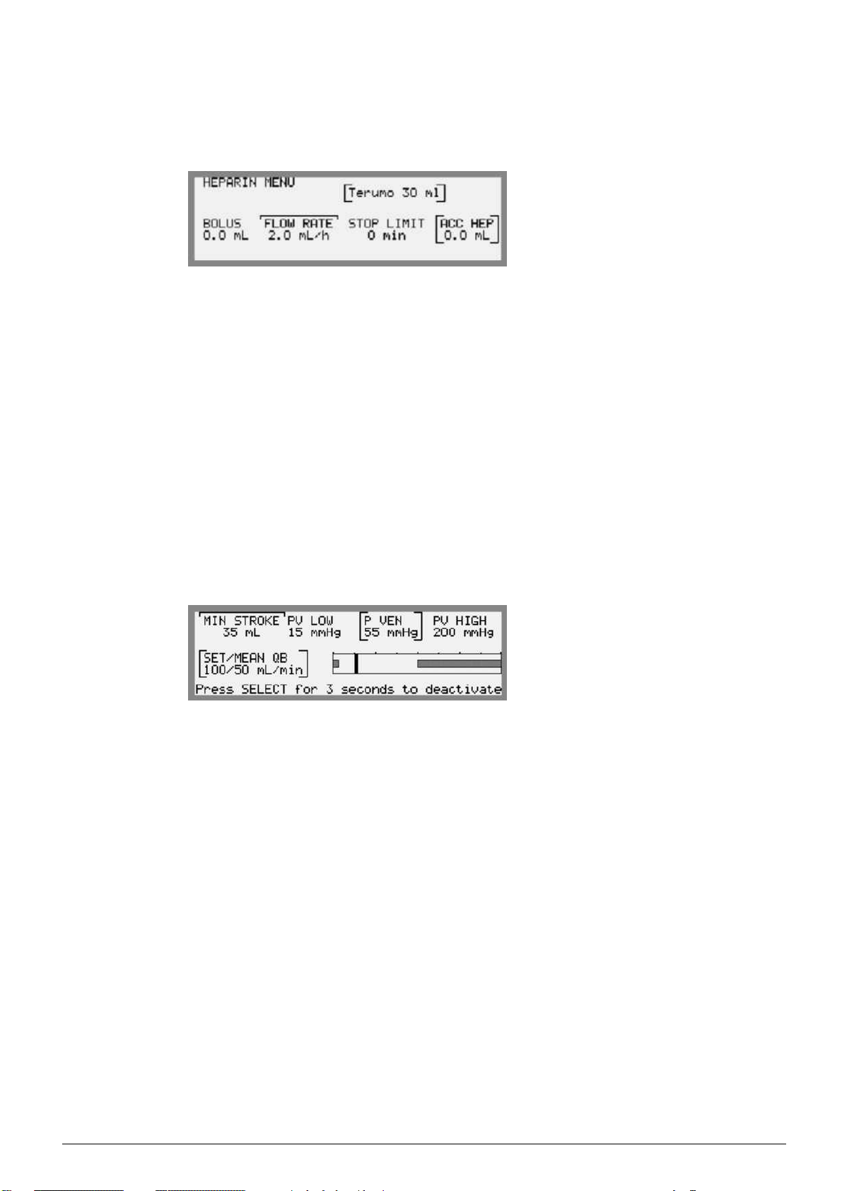
Heparin
From the Blood Path main menu; select HEPARIN by using the
Keypad to reach the sub menu.
The following will be shown on the Information Display:
Type of syringe (e.g. Terumo 30 mL).
BOLUS; set heparin solution bolus volume.
FLOW RATE; set heparin solution flow rate
STOP LIMIT; set stop time in minutes at which the heparin pump
should stop before treatment end
ACC HEP; sum of accumulated bolus volume during priming and total
accumulated volume since treatment start
The heparin pump will run concurrent to the blood pump in double
needle treatment. In single needle treatment it will be running
continuously irrespective of if the blood pump is running or not.
Single needle
From the Blood Path main menu; select SINGLE NEEDLE by using
the Keypad to reach the sub menu.
The following will be shown on the Information Display:
MIN STROKE; displays the low alarm limit for the stroke volume
PV LOW; low venous pressure alarm limit
P VEN; c urrent venous pressure
PV HIGH; high venous pressure alarm limit
SET/MEAN QB; displays set and mean blood flow rates. The
set blood flow rate (arterial) is to be set/adjusted using the
Blood Pump Up/Down keys. The mean blood flow rate is the effective
blood flow rate displayed when performing single needle treatment
3:14
AK 96
®
Operator's Manual - Operating the Machine
HCEN12239 Revision 12.2010
Program version 3.xx
Page 76

BPM button
Press the BPM button to reach the BPM main menu. On this menu
blood pressure measuring can be activated. For instructions see chapter
11 in part 2.
Fluid Bypass button
The Fluid Bypass button is used to manually bypass the dialysis fluid
from the dialyzer.
UF Start/Stop button
The UF Start/Stop button is used to start and stop the ultrafiltration.
Fluid Path button
Press the Fluid Path button to reach the Fluid Path main menu. In
this menu parameter settings and functions related to dialysis fluid
can be set/activated.
The following will be shown on the Information Display:
UF; calculated ultrafiltration rate and profiling type
CONC; selected concentrate
TEMP; current dialysis fluid temperature
COND; c urrent conductivity value
DIA FLUID FLOW; current dialysis fluid flow rate
DIASCAN; function activated or not activated
TMP; current transmembrane pressure
HCEN12239 Revision 12.2010
Program version 3.xx
AK 96®Operator's Manual - Operating the Machine
3:15
Page 77

Ultrafiltration
From the Fluid Path main menu; select UF by using the Keypad to
reach the sub menu.
The following will be shown on the Information Display:
SET UF;setultrafiltration volume (patient weight loss)
SET PRIMING UFR; set ultrafiltration rate during priming before
blood is detected
SET MIN UFR; set minimum ultrafiltration rate during treatment
PROFILING; refer to chapter 7 "Profiling" in part 1
UF RATE; calculated ultrafiltration rate
ACC UF; accumulated ultrafiltration volume (patient weight loss)
ISOL UF; refer to chapter 6 "Isolated Ultrafiltration" in part 1
Concentrates
From the Fluid Path main menu; select CONC by using the Keypad to
reach the sub menu. For instructions on connecting and selec
ting
concentrates see "Connect/Confirm Concentrates", page 4:7 in part 1.
Temperature
From the Fluid Path main menu; select TEMP by using the Keypad to
reach the sub menu.
The following will be shown o
n the Information Display:
SET TEMP; set dialysis fluid temperature
SET LOW; low alarm limit for temperature
SET HIGH; high alarm limit
for temperature
TEMP; current dialysis fluid temperature
3:16
AK 96
®
Operator's Manual - Operating the Machine
HCEN12239 Revision 12.2010
Program version 3.xx
Page 78

Conductivity
From the Fluid Path main menu; select COND by using the Keypad to
reach the sub menu.
The following will be shown on the Information Display:
SET NA; set sodium value
SET HCO3; set bicarbonate value
PROFILING; see chapter 7 in part 1
COND (C/P); current dialysis fluid conductivity value, where C is
the current conductivity value from the control system, and P is the
current conductivity value from the protective system
SET COND (C/P); set dialysis fluid conductivity value, where C is
the set conductivity value from the control system, and P is the set
conductivity value from the protective system
PH; current dialysis fluid pH value
Dialysis fluid flow rate
From the Fluid Path main menu; select DIA FLUID FLOW by using
the Keypad to reach the sub menu.
The dialysis fluid flow rate is a preset parameter value which cannot be
adjusted by the operator during priming. The value can however be
set in ( SET TREATMENT DIA FLUID FLOW) during pr
iming, but
will not be effective until treatment start ( when the priming detector
detects blood in the venous blood line). In treatment the operator has
access to adjust the value.
The following will be shown on the Information Display:
SET TREATMENT DIA FLUID FLOW; set dialysis fluid flow rate
ACTUAL DIA FLUID FLOW; current dialysis fluid flow rate
Press SELECT 3 seconds to start CSBM;thistextis
used when activating concentrate stand-by mode. See "Concentrate
Stand-by Mode" page 3:30 in part 1 for instructions.
HCEN12239 Revision 12.2010
Program version 3.xx
Diascan
From the Fluid
®
Path main menu; select DIASCAN by using the
Keypad to reach the sub menu. For instructions on settings and
activation of the Diascan function see chapter 12 in part 2.
AK 96®Operator's Manual - Operating the Machine
3:17
Page 79

Transmembrane Pressure
From the Fluid Path main menu; select TMP by using the Keypad to
reach the sub menu.
The following will be shown on the Information Display:
SET LOW; low transmembrane pressure alarm limit
TMP; current transmembrane pressure
SET HIGH; high transmembrane pressure alarm limit
In this display, upper cursors will be placed on both the low and the
high transmembrane pressure alarm limits.
To move the complete alarm window(both low and high alarm limits
will change simultaneously), first press the Select key. Then move
the window on the scale using the Up and Down Display keys.Close
using the Select key.
To adjust one alarm limit at a time, first press the Left or
Right Cursor key to select alarm limit. Then press the Select key to open
the position. Change the value using the Up and Down Display keys.
Close using the Select key.
3:18
AK 96
®
Operator's Manual - Operating the Machine
HCEN12239 Revision 12.2010
Program version 3.xx
Page 80

Mute button
The Mute button is used to silence the buzzer and to activate the night
light function.
Attention button
Attention button, see the initial parts of chapter 14 "Attention Alarms"
in part 3.
Alarm button
Alarm button, see the initial parts of chapter 13 "Alarms" in part 3.
Air Detector button
Air Detector button, see "Air Detector Alarm"
on page 13:19 in part 3.
HCEN12239 Revision 12.2010
Program version 3.xx
AK 96®Operator's Manual - Operating the Machine
3:19
Page 81

Blood Pump button
The Blood Pump button is used to start and stop the blood pump at t he
set blood flow rate.
BloodPumpUp/Downkeys
When pressed, this Blood Pump Up key will increase the blood flow
rate.
When pressed, this Blood Pump Down key will decrease the blood
flow rate.
When any of the Blood Pump Up or Blood Pump Down key is pressed,
the BLOOD FLOW MENU will be displayed on the Information
Display.
The following will be shown on the Information Display:
SET QB; set blood flow rate
ACTUAL QB; current blood flow rate
VEN PRESS; current venous pressure
ART PRESS; current arterial pressure
Keypad
The Keypad consists of Cursor keys, Display Up/Down keys,
Select key and Back key.
Select key
The Select key is used to open and close settings of the menus on the
Information Display. The operator is requested to use the Select key for
instance when activating/deactivating functions and confirming
attention alarms.
3:20
The Select key is also used to go into the positions of the menus; from
the main menus and forwards between the menus of the subsections.
®
AK 96
Operator's Manual - Operating the Machine
HCEN12239 Revision 12.2010
Program version 3.xx
Page 82

Back key
The Back key is used to step backwards. When pressed for 3 seconds
from a sub menu t he Treatment Overview Menu will resume.
Whenever the Back key is lit, it can be pressed to step backwards.
Cursor keys
The Cursor keys are used to step within the menus on the Information
Display. The Right Cursor key moves the cursor in a clockwise
direction and the Left Cursor key moves the cursor anticlockwise.
Right Cursor key
Left Cursor key
Display Up/Down keys
The Display Up/Down keys are used for setting and changing values
of parameters shown on the Information Display. The Display Up key
increases the value and the Displa
y Down key decreases the value.
The keys can be used in two ways; by briefly pressing one of the keys
repeatedly in small steps or, if
the intension is a faster change of the
value, by pressing the key pressed in until the proper value is shown.
The Display Up/Down keys a
re also to be used to scroll up and down
when lists are displayed on the Information Display. For further
information on how to use the keys in these lists, see either in "Alarms"
on page 13:1 in part 3 or i
n "Disinfection History" on page 8:4 in part 1.
DisplayUpkey
Display Down key
HCEN12239 Revision 12.2010
Program version 3.xx
AK 96®Operator's Manual - Operating the Machine
3:21
Page 83

Information Display
Together with the Keypad, the Information Display is used for
activating/deactivating functions, starting/stopping procedures and
selecting options in addition to setting parameters and alarm limits.
The Information Display also displays parameter values during
priming and treatment procedures, it displays alarm and attention
alarm messages and, if a function is currently active during treatment,
this is also displayed here.
During priming and treatment procedures the Information Display will
always be lit showing parameter values on the Priming and Treatment
Overview Menus. These displays will immediately disappear when a
function button on the Operator's Panel is pressed. The Priming or
Treatment Overview Menus will automatically resume 20 seconds
after the last time a button was pressed.
When an alarm is generated and the alarm button is pressed, an alarm
list containing alarm messages will appear on the Information Display
(besides other machine alarm actions). When an attention alarm is
generated and attention button is pressed, the attention alarm
be read on the Information Display.
text is to
Viewing Angle Adjustment
Press the Venous Pressure and Time button simultaneously. Keep
them pressed in, and the Display Up/Down keys will light up. While
continuing to keep the Venous Pressure and the Time button pressed
in, adjust the viewing angle of the Information Display using the
Display Up/Down keys.
3:22
AK 96
®
Operator's Manual - Operating the Machine
HCEN12239 Revision 12.2010
Program version 3.xx
Page 84

Cursors
When a menu is shown on the Information Display, each position of
the menu can be pointed out by the use of a c ursor. There are four
different cursors, three of them can be manually moved by the operator
using the Cursor keys. One has a fixed position on the menu.
Upper Cursor
This cursor indicates that the position has been selected and is possible
to open by using the Select key. If the position holds a function, the
subsection will be entered and a new menu will appear. If the position
holds a parameter the cursor will move to the lower position. The
Upper Cursor can be moved within the menu to select another position
by using the Cursor keys.
Lower Cursor
This cursor indicates that the position has been opened and it is
possible for the operator to c hange the value of the parameter using the
Display Up/Down keys. After the proper value has been set, close
the position using the Select key and the cursor will move to the next
position of the menu.
Cursor Brace
This cursor indicates that the position has been pre selected. The cursor
can be moved within the menu to select another position by using the
Cursor keys.
Display Brace
This cursor has a fixed position and displays the value of a parameter.
The position cannot be entered or moved by the operator.
Overview Displays
The Treatment Overview Menu will start to be displayed and continues
to be displayed at all t
imes during treatment when blood is detected.
Current parameter values during treatment are displayed here.
Activated functions are displayed at the bottom of the overview menus,
in the activity fiel
d.
The Treatment Overview Menu is divided up in two parts, both
showing curren
t treatment parameters and which functions are
activated at the moment. Switch between the two parts using the
Back key.Thefirst part containing current blood flow rate is always
present when
the treatment is ongoing but can easily be changed to the
second part using the Back key. The second part will then be displayed
for 20 s econds and after this the first part will automatically return.
HCEN12239 Revision 12.2010
Program version 3.xx
When any other menu is displayed during treatment, the Back key can
be pressed for 3 seconds if the Treatment Overview Menu is to be
immedi
ately displayed.
AK 96®Operator's Manual - Operating the Machine
3:23
Page 85

The following will be shown on the Information Display when the first
part of The Treatment Overview Menu is displayed:
QB; current blood flow rate
P VEN; c urrent venous pressure
P ART; c urrent arterial pressure
UF RATE; current ultrafiltration rate
Activated functions are displayed at the bottom of the overview menu,
in the activity field.
The second part of the overview shows the following on the
Information Display:
ACC QB; accumulated blood volume since treatment sta
rt
ACC HEP; accumulated infusion volume since treatment start
ACC UFV; accumulated ultrafiltration volume (patient weight loss)
since treatment start
UF RATE; current ultrafiltration rate
Activated functions are displayed at the bottom of the overview menu,
in the activity field.
The first part of the Treatment Overvi
ew Menu for single needle
treatment differs from the overview when performing double needle
treatment, showing parameters of interest when single needle mode is
active. Refer to chapter 5 in pa
rt 1.
3:24
AK 96
®
Operator's Manual - Operating the Machine
HCEN12239 Revision 12.2010
Program version 3.xx
Page 86

The Ultrafiltration Control
During treatment the following equation is always applicable:
Treatment time and UF volume can be set within certain limits.
The machine will automatically calculate and show the UF rate in
litres/hour. When treatment time or UF volume is changed the UF
rate will also change. The operator has to confirm the automatically
set TMP alarm limits, set around the current TMP value, via the TMP
confirm menu displayed on the Information Display.
An example on how a UF setting is to be done is shown as follows:
1. Press the Time button and set the treatment time (SET)usin
gthe
Keypad.
2. Press the Fluid Path button, select UF and set the UF volume
(SET UF).ThecalculatedUFratewillbed
isplayed in UF RATE.
3. When the flashing UF Start/Stop button is pressed (lights up), the
ultrafiltration starts. The automatically set current TMP value,
and the set (centralized) alarm
limits, has to be confirmed by the
operator via the TMP confirm menu displayed on the Information
Display. Note that the alarm limits should be set in accordance
with the UF rate and dialy
CAUTION
When negative TMP alarm limits are set, the operator will not be
notified via alarm o
However, it is possible for the authorized technician to preset the
machine so that when negative TMP alarm limits have been set,
such an attent
r attention alarm
ion alarm occurs.
zer UF coefficient.
that backfiltration may occur.
CAUTION
HCEN12239 Revision 12.2010
Program version 3.xx
An attention alarm may appear if an incorrect combination of settings
have been m
ade, e.g. the time is set to 0.00 and the UF volume is set.
The alarm will disappear as soon as the time is sufficiently increased.
AhighU
F rate limit is automatically calculated and set as 120 % of the
calculated UF rate. This limit is the highest UF rate during treatment.
AK 96®Operator's Manual - Operating the Machine
3:25
Page 87

If, for any reason, the UF rate has been too low during a period of
time, the machine will try to compensate for this by increasing the UF
rate, but within the UF rate limits.
3:26
AK 96
®
Operator's Manual - Operating the Machine
HCEN12239 Revision 12.2010
Program version 3.xx
Page 88

Power Failure
Battery Back-up Operation
The machine is equipped with a back-up battery. In case of a power
failure, the battery will supply the machine with power. The settings
and accumulated values are stored by the machine. The battery
supplies the machine with power to all functions except for heating the
dialysis fluid. This means that a low temperature alarm will occur
after the power failure.
When a power failure occurs an attention alarm will be displayed
indicating that the m achine is using the battery back-up and also for
how much time it will last:
When only one minute remains of battery power an attention ala
rm
will be displayed:
Note
• If the machine has been used on battery back-up, note that the
back-up battery will not have full capacity until it has been
recharged by the machine.
Note
Override Battery Back-up Operation
If there is a need to overri
de the battery back-up function during power
failure, press and release the halt button at the rear of the machine. The
machine will then shut down and will continue to be off until main
power returns. When m
ain power returns the machine will perform a
recovery, see Recovery from Machine Shut Down on page 3:29.
HCEN12239 Revision 12.2010
Program version 3.xx
Override of the bat
tery back-up function can be used when there is a
need to switch off or restart the machine for instance when it needs to
be moved.
AK 96®Operator's Manual - Operating the Machine
3:27
Page 89

Machine Shut Down
In case of a battery failure simultaneous with a power failure the
machine will shut down and a segment on the Time Display will
be fl ashing. The settings and accumulated values are stored by the
machine. When the power returns the machine will perform a recovery,
see Recovery from Machine Shut Down on page 3:29.
Return the Blood During Machine Shut Down
During a machine shut down, it is possible to manually return the
blood to the patient.
1. Clamp the arterial blood line and disconnect it from the patient.
2. Connect the arterial blood line to the rinse-back solution and
remove the clamp.
3. Open the cover of the blood pump an
d turn the blood pump
manually.
4. When the required amount of blood has been returned to the
patient, clamp the venous bl
ood line and disconnect it from the
patient.
WARNING
During manual procedure to return blood to patient in power failure,
the operator assumes responsibility for visually monitoring all safety
parameters which the machine cannot monitor in a power failure
(e.g. air detection).
WARNING
3:28
AK 96
®
Operator's Manual - Operating the Machine
HCEN12239 Revision 12.2010
Program version 3.xx
Page 90

Recovery from Machine Shut Down
In case of a short power failure, or a longer one where the machine
shuts down, the settings and accumulated values are stored by the
machine. If the machine has passed function check and time has
appeared on the Time Display before power failure, the machine will
perform a recovery when power returns. If the function check was not
completed before the power failure occurred, a function check will be
done when power returns.
When the machine performs a recovery an attention alarm will appear
and the buzzer sounds. The text “reC” is shown on the Time Display.
The operator must confirm the recovery after restart by pressing the
Select key. The machine will then continue the treatment from where
it was interrupted.
CAUTION
Check treatment parameters after a recovery.
CAUTION
Note
• If the attention:
appears, there will be no support f
or the buzzer and no flashing
segment on the Time Display during power failure. However,
the settings and accumulated values are stored by the machine.
When it has been confirmed, th
e machine will not restart
automatically.
The On/Off button has to be pressed to recover function.
• The machine will still be able to operate since this is not the
same battery as the back-up battery. Contact an authorized
technician to chang
e or recharge the battery.
• During power failures, when the buzzer is muted, the current
consumption from
the battery is high. In order to avoid
this high consumption, switch the machine off by pressing
the On/Off button for 3 seconds instead of pressing the
Mute button.W
hen the power returns, switch on again using
the On/Off button. A normal recovery will now follow.
Note
HCEN12239 Revision 12.2010
Program version 3.xx
AK 96®Operator's Manual - Operating the Machine
3:29
Page 91

Handling Features
Concentrate Stand-by Mode
When the machine has been switched on, has passed the function
check with proper concentrates connected, and the bypass path on the
Flow Diagram lights up green, it is possible for the machine to enter a
stand-by mode where the consumption of concentrates will be stopped.
This stand-by mode, called concentrate stand-by mode, can be
activated before or after the flashing Fluid bypass button has been
pressed during priming i.e. before or after the priming of the fluid
compartment of the dialyzer has been performed. (It cannot be
activated if blood has been detected.)
Concentrate stand-by mode can be manually activated (default
function) or automatically activated by preset.
On request from the clinic, an authorized technician can preset the type
of presets for Concentrate stand-by mode that best suits the routine
procedures of the specificclinic.
There are two presets that can be used, separately or in combination:
1. Automatic activation of concentrate stand-by mode when time is
shown on the time display and the bypass path of the Flow Diagram
lights up green. The time for activation may be straight away when
the bypass path lights up green, or for a preset amount of time after.
2. The time for automatic activation can also be preset to be when
priming volume achieved menu is displayed during priming.
When the concentrate stand-by mode is active, the
CONCENTRATE STANDBY MODE menu will be displayed
at the Information Display. The bypass path of the Flow Diagram will
be orange.
In addition to the above-mentioned presets, the machine can be
preset to automatically turn off the water intake at the same time as
Concentrate stand-by mode is active. In this case, the consumption of
both water and concentrates will be stopped. The handling procedures
will be the same.
3:30
AK 96
®
Operator's Manual - Operating the Machine
HCEN12239 Revision 12.2010
Program version 3.xx
Page 92

Procedure for manual activation
1. Press the Fluid path button, select DIA FLUID FLOW using
the Keypad.
2. Press the Select key for 3 seconds to activate concentrate
stand-by mode.
3. The CONCENTRATE STANDBY MODE menu will now be
displayed on the Information Display.
Resume fluid preparation
To resume the dialysis fluid preparation (Concentrate stand-by
mode deactivated) press the Select key for 3 seconds when the
CONCENTRATE STANDBY MODE is displayed. The dialysis fluid
will be ready within approximately 2 m inutes.
If dialysis fluid preparation has not been resumed during priming, it
will automatically be resumed when blood is detected in the priming
detector after treatment start. Dialysis fluid preparation will also
automatically be resumed when concentrate stand-by mode has been
active for more than one hour.
HCEN12239 Revision 12.2010
Program version 3.xx
AK 96®Operator's Manual - Operating the Machine
3:31
Page 93

Miscellaneous
Change of BiCart®cartridge during Treatment
If the BiCart cartridge needs to be replaced by a new one during
treatment, close the latches for at least 2 seconds before attaching
the new cartridge. This is necessary in order for the machine to
automatically prime the new BiCart cartridge. Instructions on how to
remove the cartridge can be read in "Machine aftercare", page 4:63
in part 1. Instructions on how to attach the cartridge can be read in
"Acidic concentrate and BiCart® cartridge", page 4:9 in part 1.
3:32
AK 96
®
Operator's Manual - Operating the Machine
HCEN12239 Revision 12.2010
Program version 3.xx
Page 94

Change of Blood Pump Segments
If the blood lines being used need a specific blood pump segment
diameter setting, the machine can be preset with 3 such variants. Check
with authorized technician.
Change of blood pump segment setting should be done before the
patient is connected.
CAUTION
Make sure a correct blood pump rotor is used. The blood pump rotor
has to be properly adjusted in order to correctly occlude the blood
pump segment being used. This is important in order to achieve the
correct blood flow. Check with the authorized technician.
CAUTION
The machine has to be in priming mode and the blood pump has to
be stopped in order for the diameter of the blood pump segment to
be changed.
1. Press the Blood Path button.
2. Select BLOOD FLOW and SEGMENT using the Keypad.
3. Press the Select key to open the parameter, adjust using the
Display Up/Down Keys.
4. Make sure to use a correct blood pump rotor. The blood
pump rotor has to be properly adjusted in order to correctly
occlude the blood pump segment being used.
5. Confirm the attention alarm:
by pressing the Select key.
HCEN12239 Revision 12.2010
Program version 3.xx
AK 96®Operator's Manual - Operating the Machine
3:33
Page 95

Change of Dialyzer and Blood lines during Treatment
There may be a need of changing the blood lines and the dialyzer (i.e.
the extracorporeal blood circuit) during the ongoing treatment due to,
for example, clotting. Sometimes it is possible to return the blood to
the patient, but it may also be necessary to immediately disconnect the
complete blood circuit from the patient, without returning the blood.
1. Press the Discontinuing button to display the
RINSE BACK MENU.
2. When NEW BLOOD CIRCUIT has been selected, press the
Select key for 3 seconds to activate discontinuing mode.
At the moment when the Select key is pressed, the blood
pump will automatically be stopped (flashing button). The
Discontinuing button lights up. This will also automatically
widen the venous pressure, the arterial pressure and the
TMP alarm limits to their priming values without subsequent
centralizing alarm. The UF rate will be reduced to minimum UF
rate (unlit UF Start/Stop button).
The menu will change and it is possible to select either to
immediately disconnect the complete blood circu
it from
the patient (DISCONNECT PATIENT) or to return the
blood to the patient before disconnecting the blood circuit
(RINSE BACK). Select the appropriate alterna
tive and continue
to the corresponding instructions as follows.
3. If rinse-back
RINSE BACK, has been selected:
3.a.
Return the blood to the patient as usual procedure.
For rinse-back instructions, see "Return The Blood",
page 4:60 in part 1. Start on poi
nt 4 of the instructions
and continue with all the instructions in "Return T he
Blood" (point 12 included) up until "Confirm Patient
Disconnection", page Co
nfirm Patient Disconnection
in part 1.
3.b.
4. If immediate pati
Continue to point 5 in these instructions.
ent disconnection
DISCONNECT PATIENT, has been selected:
3:34
AK 96
4.a.
4.b.
Check that the blood pump has been stopped.
Clamp the a
rterial and venous blood lines and
disconnect the blood lines from the patient.
4.c.
®
Operator's Manual - Operating the Machine
Continue to point 5 in these instructions.
HCEN12239 Revision 12.2010
Program version 3.xx
Page 96

5. Check that the arterial and venous blood lines has been
completely disconnected from the patient. Confirm this by
pressing the Select key for 3 seconds and the menu will
change to the DISMOUNT OLD BLOOD CIRCUIT menu.
When patient disconnection has been confirmed, the air detector
will be deactivated and the dialysis fluid will automatically be
bypassed from the dialyzer.
6. Disconnect the dialysis fluid tubes from the dialyzer and
connect them to the safety couplings of the machine. Remove
the dialyzer and the blood lines; follow the instructions
in "Machine aftercare", page 4:63 in part 1, point 25 and
additional warning.
7. Attach new dialyzer and blood lines; follow the
corresponding instructions in "Attach Disposables", starting
on page 4:13 in part 1.
8. Press the Select key when new disposables have been
attached, the Priming button lights up indicating that priming
mode has been activated.
9. Prime and de-air the new blood circuit as usual procedure.
Follow the corresponding instructions starting on page 4:40
for "Manual Priming and Rinsing Procedure" and on page
4:46 for "Assisted Priming and Rinsing Procedure"
Resume Treatment
10. Check/adjust the treatment parameters for the continuing treatment
(see "Always Check/Adjust", page 4:52) in part 1.
11. Connect the blood lines and start the treatment as usual procedure.
See corresponding instructions in "Connect the Patient", page 4:53
and "Start the Treatment", page 4:56 in part 1.
Especially note that all treatment parameters, set values as well
as accumulated values, from treatment start up until where it was
interrupted have been saved by the machine. If the Diascan or
Profiling functions have been previously activated, attention alarms
will be generated to give the operator instructions on how to set/adjust
the values for the continuing treatment.
in part 1.
HCEN12239 Revision 12.2010
Program version 3.xx
AK 96®Operator's Manual - Operating the Machine
3:35
Page 97

Infusions during Treatment
It is possible to give the patient infusions/transfusions/medications
during treatment via the extracorporeal blood circuit. As a matter of
principle, transfusions and medications are to be administered in the
venous blood line after the dialyzer.
Infusions may be administered both in the arterial blood line or in the
venous blood line, depending on type of infusion. Note especially
that any infusion/transfusion/medication given to the patient via the
extracorporeal blood circuit during treatment, must pass the venous
drip chamber and the activated air detector.
Post-blood pump infusions
Lines for infusions are first and foremost to be connected to
the extracorporeal blood circuit post-blood pump, i.e. after
the blood pump, preferably to the venous drip chamber. The
corresponding figure shows post-blood pump connection of
infusion. The infusion line is marked
Since there is a positive pressure in the blood lines post-blood
pump (including the venous drip chamber), an overpressure must
be established in the infusion line. Normally, this is done by
using an infusion pump, an overpressure cuff or, if necessary, by
manually creating an overpressure.
.
Pre-blood pump infusions
There is also the possibility of connecting the infusion line to
the extracorporeal blood circuit pre-blood pump, i.e. before the
blood pump. The corresponding figure shows pre-blood pump
connection of infusion. The infusion line is marked
Since there is a negative pressure in the blood lines pre-blood
pump, pay attention of the possibility of air entering the blood
lines. Always carefully supervise pre-blood pump infusions.
Do not use infusion pump or any other methods to create
overpressure in the infusion line.
WARNING
When using a central venous catheter, and connecting the infusion
line pre-blood pump, ensure that the arterial blood line towards
the patient is properly clamped, before the infusion is started and
during the ongoing infusion. This is to prevent air from entering
the patient's blood stream since the pressure in the central venous
catheter is sometimes negative.
.
WARNING
3:36
AK 96
®
Operator's Manual - Operating the Machine
HCEN12239 Revision 12.2010
Program version 3.xx
Page 98

Chapter 4
Hemodialysis - Double Needle
Treatment
Contents
StarttheMachine ........................................
CheckBeforeSwitchingtheMachineOn ...................
SwitchtheMachineOn .................................
FunctionCheck ....................................
Set-upthemachine .......................................
Connect/ConfirmConcentrates ...........................
ConcentrateCombinations ............................
AttachDisposables ....................................
Dialyzer-Attach ...................................
ArterialBloodLine-Attach ...........................
Details .........................................
Preparationsiftheheparinpumpistobeused ...........
VenousBloodLine-Attach ...........................
Details .........................................
DialysisFluidTubes-Attach ..........................
Attachingprocedure ..............................
Priming ...............................................
General .............................................
Manual Priming and Rinsing Pro
CheckBeforePriming ...............................
PrimingProcedure ..................................
Extra Priming Procedu
Recirculation Primi
Assisted Priming a
Check Before Prim
Priming Proce
Extra Primin
Recircula
Treatmen
Discontinuing ...........................................
t ..............................................
Set Trea
Conn
Sta
ConfirmTreatmentEnd .................................
ReturnTheBlood .....................................
Confi
Machineaftercare .....................................
tmentParameters ...............................
Always
rttheTreatment ....................................
Pr
Check/Adjust ................................
ectthePatient ....................................
essure Alarm Limits Setting .........................
AlarmLimitCentralizingFunction ...................
Arterial/VenousPressure ...........................
TMP ..........................................
rmPatientDisconnection ...........................
ndRinsingProcedure ....................
dure ..................................
gProcedure ..............................
tionPrimingProcedure .......................
re ..............................
ngProcedure .......................
ing ...............................
cedure .....................
4:2
4:2
4:2
4:3
4:7
4:7
4:8
4:13
4:15
4:16
4:19
4:25
4:28
4:31
4:35
4:36
4:38
4:38
4:40
4:40
4:40
4:44
4:44
4:46
4:46
4:46
4:50
4:50
4:52
4:52
4:52
4:53
4:56
4:57
4:57
4:57
4:58
4:59
4:59
4:60
4:62
4:63
HCEN12239 Revision 12.2010
Program version 3.xx
AK 96®Operator's Manual - Double Needle Treatment
4:1
Page 99

Start the Machine
Check Before Switching the Machine On
• That the mains cable is connected to a mains supply with protective
earth.
• That the main s witch on the rear of the machine is in the on position
(indicated by a lit segment shown on the Time display).
• That the water supply is connected to the machine (inlet water
tube) and switched on.
• That the drain tube (outlet tube) is properly placed with an air gap
between the machine and the drain/sewer system.
• That the dialysis fluid tubes are connected to the safety couplings
of the machine.
Switch the Machine On
Note
• If the machine has been stored with chemical disinfectant, this
solution must be rinsed out of the system before any treatment
can be initiated.
Note
Switch the machine on by pressing the On/Off button for three seconds.
At this moment, the buzzer will sound shortly and the computer
processor of the machine will count up (displayed on the Time display).
The current program version ins
talled on the machine w ill be displayed
on the Information Display.
After a short while all the lamps on the operator's panel will light up
simultaneously. The operator must look and check that the lamps
are functionin
g. If any lamp does not light up, contact an authorized
service technician. The machine will also test the buzzer sound.
4:2
AK 96
®
Operator's Manual - Double Needle Treatment
HCEN12239 Revision 12.2010
Program version 3.xx
Page 100

Function Check
CAUTION
In order to protect the operator’s fingers, do not attach the blood
lines during the function check of the blood part, since the blood
pump rotor and the blood line clamps will be moving during the
check.
CAUTION
When the machine starts up it always carries out checks on internal
safety and calibrations; the function check. "F.C h " will appear on
the Time Display and the Treatment Overview Menu will be shown
on the Information Display. See "Overview Displays" on page 3:23
in part 1 for further information.
The Back button lights up. If pressed, the second part of the Treatment
Overview Menu appears. Switch between the two parts using
the
Back button.
The Blood part will be checked first, it will only t
ake a few minutes.
During this time the blood pump cover must be closed and the pressure
transducers of the blood lines cannot be connected.
When the Priming button lights up,theBlood Pump button starts to
flash, the Air Detector button lights up and it is now possible to attach
the blood lines (if not done befo
re switching the machine on). See
"Attach Disposables" starting on page 4:13 in part 1. It is also possible
to start the priming procedure of the blood part. See "Priming" starting
on page 4:38 in part 1. Note t
hat if a chemical disinfection program
has been performed prior to the function check, the function check is
prolonged. An attention alarm appears to guide the operator in this
case.
To b e ab le t o finish the function check, the proper concentrates must
be connected. See
"Connect/Confirm Concentrates" starting o n page
4:7 in part 1. Note that if BiCart cartridge is used, it can be attached
after finalized function check. An attention alarm appears requesting
the operator to
attach the cartridge. The buzzer can be permanently
muted. The BiCart cartridge must be attached to obtain green bypass
path of the Flow Diagram.
HCEN12239 Revision 12.2010
Program version 3.xx
The dialysis fluid tubes must remain connected to the safety couplings
of the machine until “F.Ch” disappears from the Time Display. Note
that if th
e optional Dialysis Fluid Filter, see "UFD- Ultrafiltered
Dialysis Fluid (option)" page 1:17 in part 1, has been installed, the
AK 96®Operator's Manual - Double Needle Treatment
4:3
 Loading...