

Galaxy GHDXS2-1430R-16F4D Installation And Hardware Reference Manual
Galaxy RAID
16-bay GHDXS2-1430R-16F4D
4G FC to SAS/SATA RAID Subsystem
Installation and Hardware
Reference Manual
Version 1.0 (9/07)

Galaxy GHDXS2-1430R-16F4D Installation and Hardware Reference Manual
ii
Contact Information
Americas
Rorke Data
76276 Golden Triangle Drive
Eden Prairie, MN 55344
USA
Tel: +1-800- 328 8147
Fax: +1-952 829 0988
sales@rorke.com
techsupport@rorke.com
http://www.rorke.com

Galaxy GHDX2-1430R-16F4D Installation and Hardware Reference Manual
iii
Copyright 2007
This Edition First Published 2007
All rights reserved. This publication may not be reproduced, transmitted,
transcribed, stored in a retrieval system, or translated into any language or
computer language, in any form or by any means, electronic, mechanical,
magnetic, optical, chemical, manual or otherwise, without the prior written
consent of Rorke Data, Inc.
Disclaimer
Rorke Data makes no representations or warranties with respect to the
contents hereof and specifically disclaims any implied warranties of
merchantability or fitness for any particular purpose. Furthermore, Rorke
Data reserves the right to revise this publication and to make changes from
time to time in the content hereof without obligation to notify any person of
such revisions or changes. Product specifications are also subject to change
without prior notice.
Trademarks
Rorke, the Rorke logo, RAIDWatch and Galaxy are registered trademarks of
Rorke Data, Inc. Other names prefixed with “GAL” and “Galaxy” are
trademarks of Rorke Data, Inc.
PowerPC® is a trademark of International Business Machines Corporation
and Motorola Inc.
Solaris and Java are trademarks of Sun Microsystems, Inc.
All other names, brands, products or services are trademarks or registered
trademarks of their respective owners.
Galaxy GHDXS2-1430R-16F4D Installation and Hardware Reference Manual
iv
Warnings and Certifications
Restricted Access Location:
This equipment is intended to be installed in a RESTRICTED ACCESS
LOCATION only.
Electric Shock Warning!
To Prevent Electric Shock:
Access to this equipment is granted only to trained operators and service
personnel who have been instructed of and fully understand the possible
hazardous conditions and the consequences of accessing non-fieldserviceable units.
FCC (applies in the U.S. and Canada)
FCC Class A Radio Frequency Interference Statement
This device complies with Part 15 of the FCC rules. Operation is subject to
the following two conditions: (1) this device may not cause harmful
interference, and (2) this device may accept any interference received,
including interference that may cause undesired operation.
NOTE:
This equipment has been tested and found to comply with the limits for a
Class A digital device, pursuant to Part 15 of the FCC Rules. These limits
are designed to provide reasonable protection against harmful interference
when the equipment is operated in a commercial environment. This
equipment generates, uses, and can radiate radio frequency energy and, if
not installed and used in accordance with the instruction manual, may cause
harmful interference to radio communications. Operation of this equipment
in a residential area is likely to cause harmful interference in which case the
user will be required to correct the interference at his own expense.
Any changes or modifications not expressly approved by the party
responsible for compliance could void the user’s authority to operate the
equipment.
Galaxy GHDX2-1430R-16F4D Installation and Hardware Reference Manual
v
WARNING:
A shielded power cord is required in order to meet FCC emission limits and
also to prevent interference to nearby radio and television reception.
Use only shielded cables to connect I/O devices to this equipment. You are
cautioned that changes or modifications not expressly approved by the party
responsible for compliance could void your authority to operate the
equipment.
This device is in conformity with the EMC.
CB
(Certified Worldwide)
This device meets the requirements of the CB standard for electrical
equipment with regard to establishing a satisfactory level of safety for
persons using the device and for the area surrounding the apparatus.
This standard covers only safety aspects of the above apparatus; it does
not cover other matters, such as style or performance.
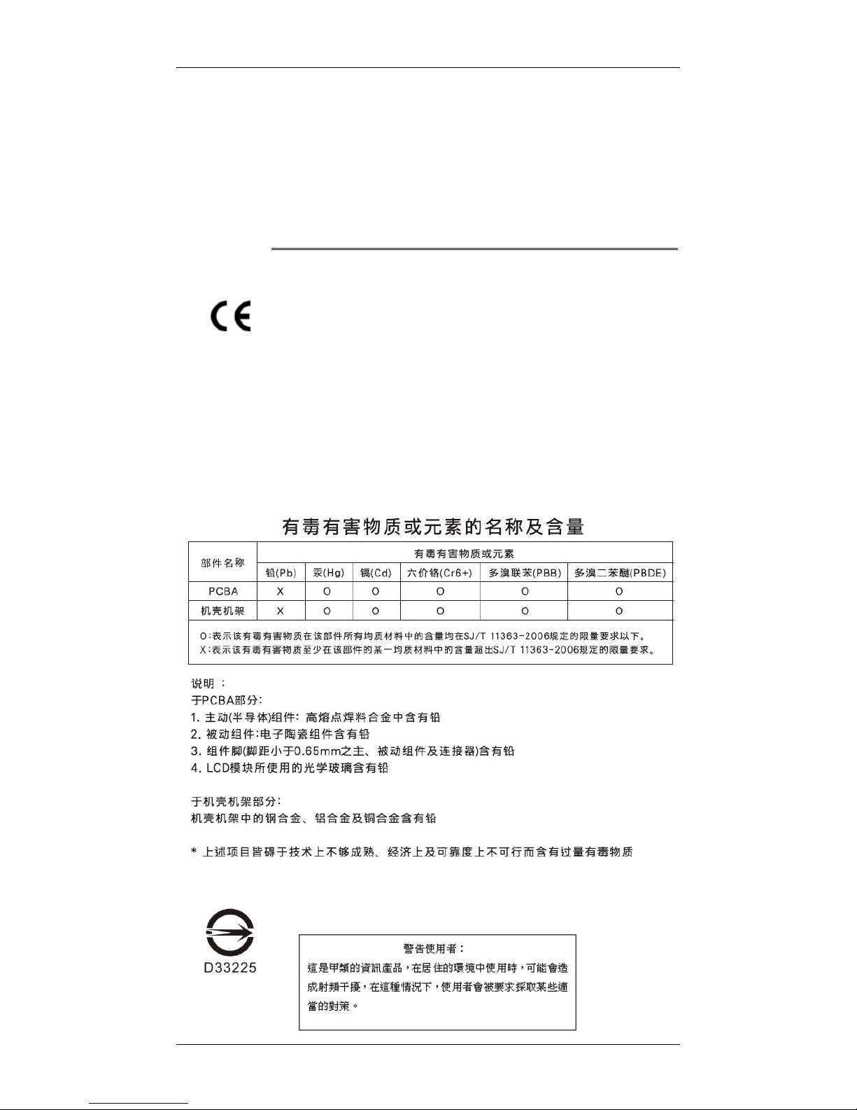
China RoHS
In Compliance with AeA China RoHS Regulations (SJ/T 11364-2006)
CCC
For Power Supplies’ compatibility to China Compulsory Certification.
ITE BSMI Class A,
CNS 13438 (for Taiwan)
Galaxy GHDXS2-1430R-16F4D Installation and Hardware Reference Manual
vi
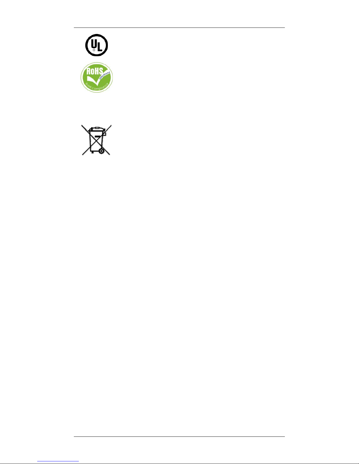
This device is in conformity with UL standards for safety.
Rorke is committed to being properly prepared and taking all the
necessary steps that will result in our compliance with the new
European directive, RoHS (2002/95/EC), on or before the specific dates
set forth in those applicable laws and regulations. Rorke is applying its
own internal efforts and expertise and is working closely with
customers and suppliers to achieve compliance while maintaining an
uninterrupted supply of quality products. Rorke is currently
investigating, evaluating, and qualifying our materials and components
to ensure that products sold on or after 1 July 2006, in such territory,
are in compliance with the above regulations.
Disposal of Old Electrical & Electronic Equipment (Applicable in the
European Union and other European countries with separate collection
systems)
This symbol on the product or on its packaging indicates that this
product shall not be treated as household waste. Instead it shall be
handed over to the applicable collection point for the recycling of
electrical and electronic equipment. By proper waste handling of this
product you ensure that it has no negative consequences for the
environment and human health, which could otherwise be caused if this
product is thrown into the garbage bin. The recycling of materials will
help to conserve natural resources.
For more details information about recycling of this product, please
contact your local city office, your household waste disposal service or
the shop where you purchased the product.
Table of Contents
C
ONTACT INFORMATION ....................................................................................................II
COPYRIGHT 2007................................................................................................................III
This Edition First Published 2007.......................................................................................iii
Disclaimer..........................................................................................................................iii
Trademarks........................................................................................................................iii
WARNINGS AND CERTIFICATIONS ......................................................................................IV
TABLE OF CONTENTS .........................................................................................................VI
Precautions and Instructions.............................................................................................IX
ESD Precautions................................................................................................................X
ABOUT THIS MANUAL ......................................................................................................... X
REVISION HISTORY ............................................................................................................. X
WHO SHOULD READ THIS MANUAL? ...................................................................................XI
Related Documentation .....................................................................................................xi
CONVENTIONS .....................................................................................................................XI
Naming ..............................................................................................................................xi
Lists ...................................................................................................................................xi
Software and Firmware Updates.......................................................................................xii
CHAPTER 1 INTRODUCTION
1.1 PRODUCT OVERVIEW ............................................................................................1-1
1.1.1 Product Introduction.................................................................................... 1-1
1.2 CHASSIS OVERVIEW ..............................................................................................1-2
1.2.1 Front Panel Overview.................................................................................1-3
1.2.2 Rear Panel Overview.................................................................................. 1-3
1.2.3 Integrated Backplane.................................................................................. 1-5
1.2.4 Physical Dimensions................................................................................... 1-5
1.3 MAJOR SUBSYSTEM COMPONENTS.......................................................................1-5

Galaxy GHDX2-1430R-16F4D Installation and Hardware Reference Manual
vii
1.3.1 LCD Keypad Panel.....................................................................................1-5
1.3.2 Drive Tray................................................................................................... 1-6
1.3.3 MUX Kit ...................................................................................................... 1-7
1.3.4 The RAID Controller Module....................................................................... 1-8
1.3.4.1 JBOD Support..........................................................................................................1-9
1.3.4.2 Controller Module Interfaces................................................................................... 1-9
1.3.4.3 DIMM Module.......................................................................................................1-12
1.3.5 BBU..........................................................................................................1-12
1.3.6 PSUs ........................................................................................................ 1-13
1.3.7 Cooling Modules....................................................................................... 1-14
1.4 SUBSYSTEM MONITORING................................................................................... 1-15
1.4.1 I2C bus.....................................................................................................1-15
1.4.2 LED Indicators.......................................................................................... 1-16
1.4.3 Firmware (FW) and RAIDWatch GUI........................................................ 1-16
1.4.4 Audible Alarms ......................................................................................... 1-16
1.5 HOT-SWAPPABLE COMPONENTS.........................................................................1-17
1.5.1 Hot-swap Capabilities............................................................................... 1-17
1.5.2 Components.............................................................................................1-17
CHAPTER 2 HARDWARE INSTALLATION
2.1 INTRODUCTION......................................................................................................2-1
2.2 INSTALLATION PREREQUISITES ............................................................................2-1
2.3 SAFETY PRECAUTIONS ..........................................................................................2-3
2.3.1 Precautions and Instructions ...................................................................... 2-3
2.3.2 Static-free Installation.................................................................................2-4
2.3.3 Preparation.................................................................................................2-4
2.4 GENERAL INSTALLATION PROCEDURE.................................................................2-5
2.4.1 Installation Procedure Flowchart................................................................. 2-6
2.5 UNPACKING THE SUBSYSTEM................................................................................ 2-6
2.5.1 Preinstalled Components............................................................................ 2-7
2.5.2 Components to be Installed........................................................................ 2-7
2.6 HARD DRIVE INSTALLATION.................................................................................2-7
2.6.1 Hard Drive Installation Prerequisites........................................................... 2-7
2.6.2 Drive Installation without MUX Kit............................................................... 2-9
2.6.3 Drive Installation with MUX Kit.................................................................... 2-9
2.7 DRIVE TRAY INSTALLATION ...............................................................................2-10
2.8 OPTIONAL MUX KIT INSTALLATION .................................................................2-12
2.9 BBU INSTALLATION ............................................................................................2-13
2.9.1 BBU Warnings and Precautions ............................................................... 2-13
2.9.2 Installation Procedure............................................................................... 2-14
2.10 RACKMOUNTING.................................................................................................. 2-16
CHAPTER 3 SUBSYSTEM CONNECTION
3.1 FC HOST CONNECTION PREREQUISITES..............................................................3-1
3.1.1 Choosing the Fibre Cables.....................................................................................3-1
3.1.2 FC Lasers .............................................................................................................. 3-2
3.1.3 SFP Transceivers .................................................................................................. 3-3
3.1.4 FC Port Dust Plugs................................................................................................3-3
3.2 TOPOLOGY AND CONFIGURATION CONSIDERATIONS..........................................3-3
3.2.1 Basic Configuration Rules...................................................................................... 3-3
3.2.2 Fibre Channel Topologies...................................................................................... 3-4
3.2.3 Host-side Topologies .............................................................................................3-4
3.2.4 Drive-side Connection............................................................................................ 3-5
3.2.5 Internal Connections.............................................................................................. 3-5
3.2.6 Unique Identifier..................................................................................................... 3-5
3.2.7 ID/LUN Mapping .................................................................................................... 3-5
3.3 DIP SWITCH...........................................................................................................3-6
3.4 SAMPLE TOPOLOGIES............................................................................................3-8
3.4.1 Multiple RAID, Fault-tolerant Connection............................................................... 3-8
3.4.2 Dual-Controller, Fault-Tolerant Connection .........................................................3-11
3.4.3 Drive-side Expansion........................................................................................... 3-12
CHAPTER 4 SYSTEM OPERATION AND MONITORING.
4.1 POWER ON .............................................................................................................4-1
4.1.1 Check List................................................................................................... 4-1
4.1.2 Power On Procedure..................................................................................4-2
4.1.3 Power On Status Check ............................................................................. 4-3

Galaxy GHDXS2-1430R-16F4D Installation and Hardware Reference Manual
viii
4.1.4 LCD Screen................................................................................................ 4-4
4.2 POWER OFF PROCEDURE ......................................................................................4-5
4.3 SYSTEM MONITORING OVERVIEW .......................................................................4-6
4.4 STATUS-INDICATING LEDS ...................................................................................4-8
4.4.1 Brief Overview of the LEDs......................................................................... 4-8
4.4.2 LCD Keypad Panel.....................................................................................4-8
4.4.3 Drive Tray LEDs .......................................................................................4-10
4.4.4 Controller Module LEDs............................................................................ 4-10
4.4.4.1 Controller Status LEDs..........................................................................................4-11
4.4.4.2 Fibre Port LEDs.....................................................................................................4-11
4.4.4.3 Restore Default LED .............................................................................................4-11
4.4.4.4 LAN Port LEDs.....................................................................................................4-11
4.4.5 BBU LED..................................................................................................4-12
4.4.6 PSU LEDs ................................................................................................ 4-12
4.4.7 Cooling Module LEDs............................................................................... 4-13
4.5 AUDIBLE ALARM .................................................................................................4-14
4.6 I2C MONITORING................................................................................................. 4-15
CHAPTER 5 SYSTEM MAINTENANCE
5.1 OVERVIEW .............................................................................................................5-1
5.1.1 About Subsystem Maintenance..................................................................5-1
5.1.2 General Notes on Component Replacement..............................................5-2
5.2 REPLACING CONTROLLER MODULE COMPONENTS ............................................5-3
5.2.1 Considerations............................................................................................ 5-3
5.2.2 Removing the Controller Module ................................................................ 5-3
5.2.3 Replacing the Controller Module.................................................................5-5
5.3 DIMM MODULE REPLACEMENT..........................................................................5-7
5.3.1 DIMM Module Considerations ....................................................................5-7
5.3.2 DIMM Module Upgrade/Replacement Procedure.......................................5-7
5.4 REPLACING A FAULTY BBU..................................................................................5-9
5.5 REPLACING A FAULTY PSU ................................................................................5-12
5.5.1 PSU Overview ..........................................................................................5-12
5.5.2 Replacing the PSU ................................................................................... 5-13
5.6 COOLING MODULE MAINTENANCE ....................................................................5-16
5.6.1 Notes on Cooling Module Maintenance.................................................... 5-16
5.6.2 Replacing a Cooling Module..................................................................... 5-17
5.7 REPLACING A FAILED HARD DRIVE ................................................................... 5-19
5.7.1 Hard Drive Maintenance Overview...........................................................5-19
5.7.2 Replacing a Hard Drive............................................................................. 5-20
5.8 REPLACING A MUX KIT......................................................................................5-22
APPENDIX A SPECIFICATIONS
A.1 TECHNICAL SPECIFICATIONS...............................................................................A-1
Environmental Specifications.....................................................................................A-1
Power Requirements...................................................................................................A-1
Certifications.................................................................................................................A-2
Warning Alarms............................................................................................................A-2
A.2 FUNCTIONAL SPECIFICATIONS.............................................................................A-2
Configuration Specifications.......................................................................................A-2
Architectural Specifications........................................................................................A-3
A.3 DRIVE TRAY SPECIFICATIONS ............................................................................. A-3
A.4 POWER SUPPLY SPECIFICATIONS......................................................................... A-3
A.5 COOLING MODULE SPECIFICATIONS................................................................... A-4
A.6 RAID MANAGEMENT........................................................................................... A-4
A.7 FAULT TOLERANCE MANAGEMENT..................................................................... A-5

Galaxy GHDX2-1430R-16F4D Installation and Hardware Reference Manual
ix
APPENDIX B SPARE PARTS AND ACCESSORIES
B.1 SPARE PARTS ........................................................................................................ B-1
B.2 ACCESSORIES........................................................................................................ B-2
APPENDIX C PINOUTS
C.1 SFP CONNECTOR PINOUTS ..................................................................................C-1
C.2 COM1 CABLE: DB9 AND AUDIO JACK PINOUTS ................................................C-3
C.3 COM1 CABLE: DB9 AUDIO JACK Y-CABLE PINOUTS........................................C-3
C.4 COM2 UPS CABLE: DB9 AND AUDIO JACK PINOUTS........................................ C-4
C.5 GAL-9011 NULL MODEM .................................................................................... C-5
C.6 LAN PORT PINOUTS............................................................................................. C-6
C.7 POWER CONNECTORS...........................................................................................C-7
C.8 CONNECTOR TYPE AND OTHER INFORMATION ..................................................C-7
C.8.1 Connector Type and Supported Connections..........................................................C-7

Galaxy GHDXS2-1430R-16F4D Installation and Hardware Reference Manual
x
Precautions and Instructions
• If it is necessary to transport the subsystem, repackage all disk drives
with its drive trays in the foam blocks in the original shipping package.
• Provide a soft, clean surface to place your subsystem on before working
on it. Servicing on a rough surface may damage the exterior of the
chassis.
• Leaving any of these drive bays empty will seriously affect the
efficiency of the airflow within the enclosure, and will consequently
lead to the system overheating, which can cause irreparable damage.
• Prior to powering on the subsystem, ensure that the correct power range
is being used.
• All modules must be properly installed before powering on the
subsystem. If a cooling module is missing, the power supply unit (PSU)
will overheat rapidly.
• If a module fails, leave it in place until you have a replacement unit and
you are ready to replace it.
• Handle subsystem modules using their retention screws, eject levers,
and the metal frames/face plates. Avoid touching PCB boards and
connector pins.
• Airflow Consideration: The subsystem requires an airflow clearance,
especially at the front and rear.
• Be sure that the rack cabinet into which the subsystem chassis will be
installed provides sufficient ventilation channels and airflow circulation
around the subsystem.
• To comply with safety, emission, or thermal requirements, none of the
covers or replaceable modules should be removed. Make sure that all
enclosure modules and covers are securely in place during operation.
• Dual redundant controller models come with two controller modules
that must be installed into the subsystem.
ESD Precautions
Observe all conventional anti-ESD methods while handling system
modules. The use of a grounded wrist strap and an anti-static work pad are
recommended. Avoid dust and debris in your work area.

Galaxy GHDX2-1430R-16F4D Installation and Hardware Reference Manual
xi
About This Manual
This manual:
• Introduces the Galaxy RAID Subsystem series.
• Describes all the active components in the system.
• Provides recommendations and details about the hardware
installation process of the subsystem.
• Briefly describes how to monitor the subsystem.
• Describes how to maintain the subsystem.
This manual does not:
• Describe components that are not user-serviceable.
• Describe the configuration options of firmware, using terminal
emulation programs, or the RAIDWatch GUI that came with your
subsystem.
• Give a detailed description of the RAID controllers embedded
within the subsystem.
Revision History
Rev. 1.0: Initial release
Who should read this manual?
This manual assumes that its readers are experienced with computer
hardware installation and are familiar with storage enclosures.
Related Documentation
• Fibre-to-SAS/SATA Series RAID Subsystem Operation Manual
• RAIDWatch User’s Manual
These two (2) documents are located in the CD included with your
subsystem package
Galaxy GHDXS2-1430R-16F4D Installation and Hardware Reference Manual
xii
Conventions
Naming
From this point on and throughout the rest of this manual, the Galaxy series
is referred to as simply the “subsystem” or the “system” and Galaxy is
frequently abbreviated as “GAL.”
Lists
Bulleted Lists: Bulleted lists are statements of non-sequential facts. They
can be read in any order. Each statement is preceded by a round black dot
“•.”
Numbered Lists: Numbered lists are used to describe sequential steps you
should follow in order.
Important information that users should be aware of is indicated with the
following icons:
NOTE:
These messages inform the reader of essential but non-critical
information. These messages should be read carefully as any directions or
instructions contained therein can help you avoid making mistakes.
CAUTION!
Cautionary messages should also be heeded to help you reduce the chance
of losing data or damaging the system.
IMPORTANT!
The Important messages pertain to using the Galaxy subsystem introduced
in this manual.
WARNING!
Warnings appear where overlooked details may cause damage to the
equipment or result in personal injury. Warnings should be taken
seriously.

Galaxy GHDX2-1430R-16F4D Installation and Hardware Reference Manual
xiii
Software and Firmware Updates
Please contact your system vendor or tech support for the latest software or
firmware updates.
Problems that occur during the updating process may cause unrecoverable
errors and system downtime. Always perform a backup of your data and
consult technical personnel before proceeding with any firmware upgrade.
NOTE:
The firmware version installed on your system should provide the
complete functionality listed in the specification sheet/user’s manual. We
provide special revisions for various application purposes. Therefore, DO
NOT upgrade your firmware unless you fully understand what a firmware
revision will do.
Product Overview 1-1
Chapter 1
Introduction
1.1 Product Overview
1.1.1 Product Introduction
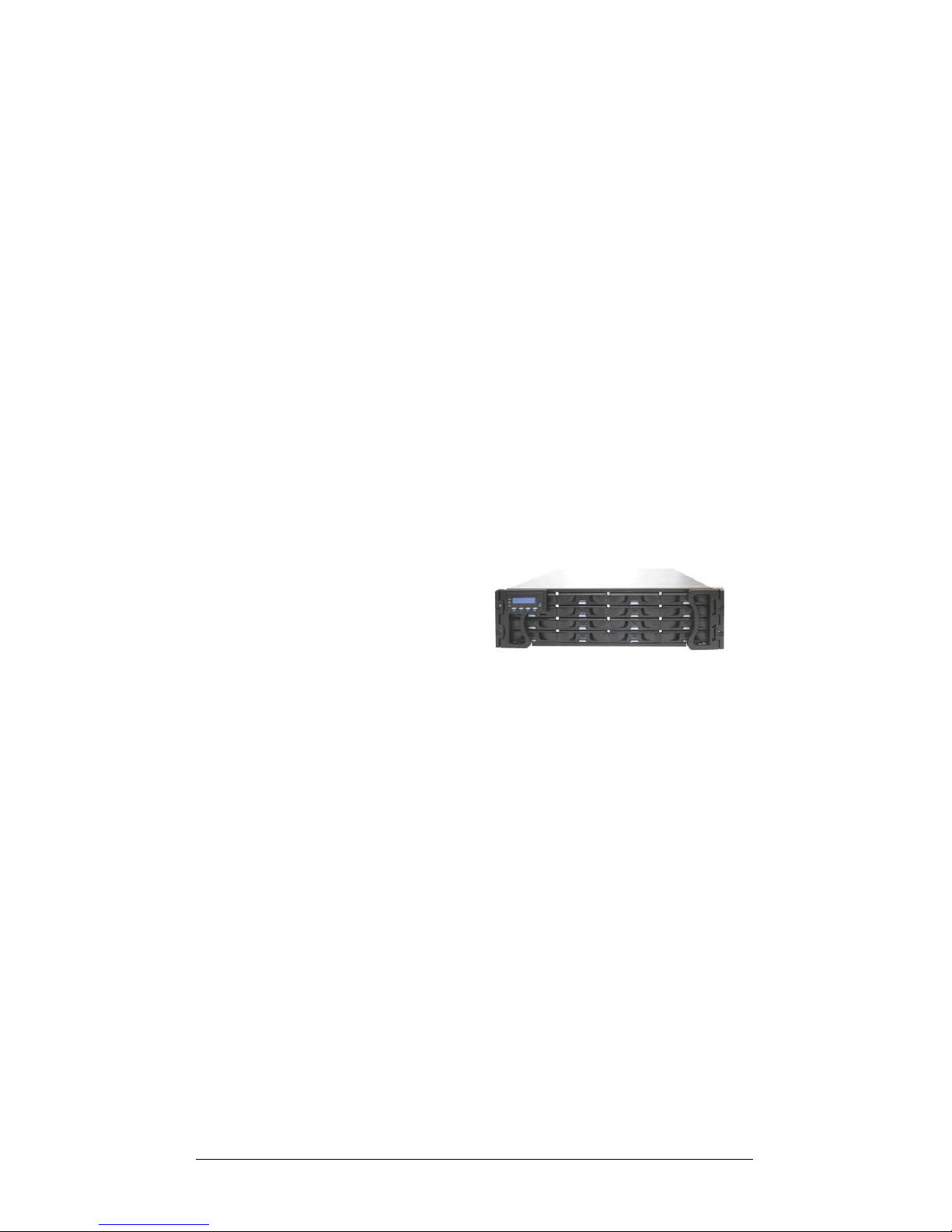
This chapter briefly introduces the Galaxy (GAL) RAID Fibre-to-SAS
(Serial Attached SCSI) subsystem. With compatible interface connectors,
the drive bays also support SATA-II (Serial ATA) disk drives. The 16-bay
model comes with up to four (4) 4Gb/s host channels and sixteen (16) hotswappable SAS/ SATA disk drives in a 3U chassis. The subsystem is
powered by Infortrend’s
proprietary ASIC400 RAID
engine, which features
expanded bandwidth and
RAID6 configurations. The
RAID controller comes
with a pre-installed
memory buffer of up to 2GB in size for transient handling of I/Os. Each
4Gb/s channel is capable of delivering data at the speed of 400MB/s. An
onboard hub (bypass) can be used to connect the corresponding FC
channels on partner controllers together to facilitate fault-tolerant
connections. A common backplane provides fault-tolerant data paths across
dual-ported SAS disk drives (over two separate SAS domains).
The subsystem is ideal for high performance and high availability storage
applications, and is highly scalable via a 4x multi-lane SAS expansion port.
Terabytes of expansion capacity can be added via the SAS 4-PHY SFF8470 expansion links to expansion enclosures.
Data cached in memory is protected by a Li-Ion battery backup unit (BBU)
that comes with an embedded EEPROM for storing BBU service data. If the
one-year life expectancy of a BBU is reached, system administrators will be
notified by event messages. The BBU is independently accessible and hotreplaceable.
Two (2) cooling modules protect the subsystem from overheating, and two
(2) hot-swappable power supply unit (PSU) modules ensure constant power
Figure 1-1: GalaxyRAID Subsystem
Galaxy GHDXS2-1430R-16F4D Installation and Hardware Reference Manual
1-2 Chassis Overview
to the subsystem. The modular design of the subsystem ensures the ease of
subsystem maintenance.
NOTE:
On receiving and unpacking your subsystem, please check the package
contents against a printed copy of Unpacking List included in kit. If any
modules are missing or appear damaged, please contact your subsystem
vendor immediately.
1.2 Chassis Overview
The GHDX2-1430R-16F4D RAID storage subsystem is housed in a 3U
metal chassis made of compact steel. The chassis can be divided into the
front and the rear sections, which are respectively accessed through the
front and rear panels. Separately-purchased rackmount rails are available
from Infortrend for installation into 19” standard racks or cabinets. Please
acquaint yourself with the locations of individual components before
proceeding with hardware installation.
NOTE:
Components accessed through the front panel are referred to as “Front
Panel Components” and components accessed through the rear panel are
referred to as “Rear Panel Components.”
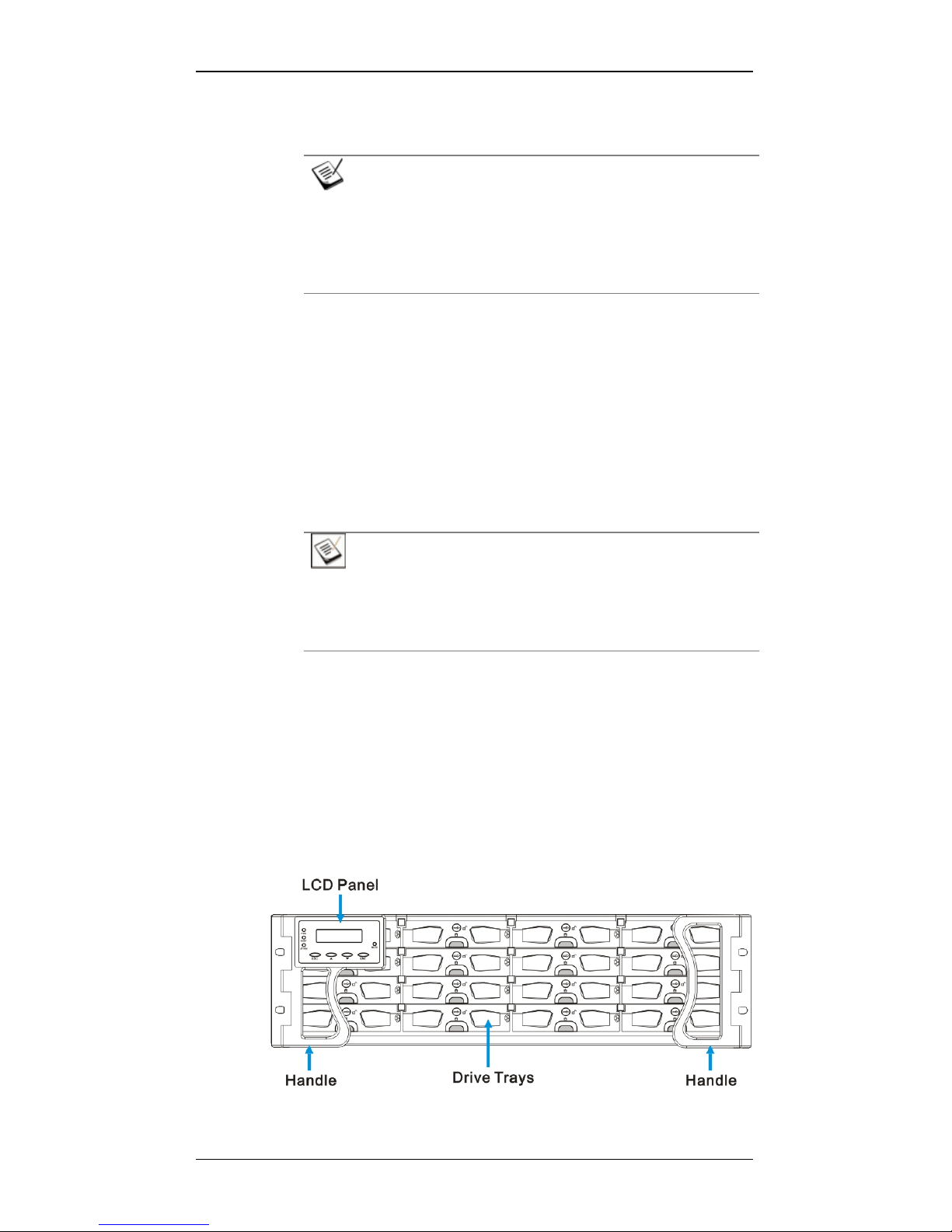
1.2.1 Front Panel Overview
The front section of the subsystem features a 4x4 layout for sixteen (16)
3.5-inch drives. One of the two forearm handles comes with an LCD
keypad panel. The LCD panel provides easy access to the subsystem’s
monitoring and configuration utilities.
The front view of the RAID subsystems is shown in Figure 1-2.
Descriptions of each front panel component are given below:
Figure 1-2: RAID with an LCD Keypad Panel
Chapter 1: Introduction
Chassis Overview 1-3
Drive bays with drive tray canisters: The front section of the
chassis houses sixteen (16) drive bays.
LCD keypad panel and handles: The forearm handles on the
sides of the subsystem provide an easier means for installing or
retrieving the chassis into and out of a rack or cabinet. The leftside handle comes with a 2 rows x 16 character s -w id e LCD keypa d
panel that can be used to access a firmware-embedded
configuration and monitoring utility. (Please refer to Section 1.3.1)
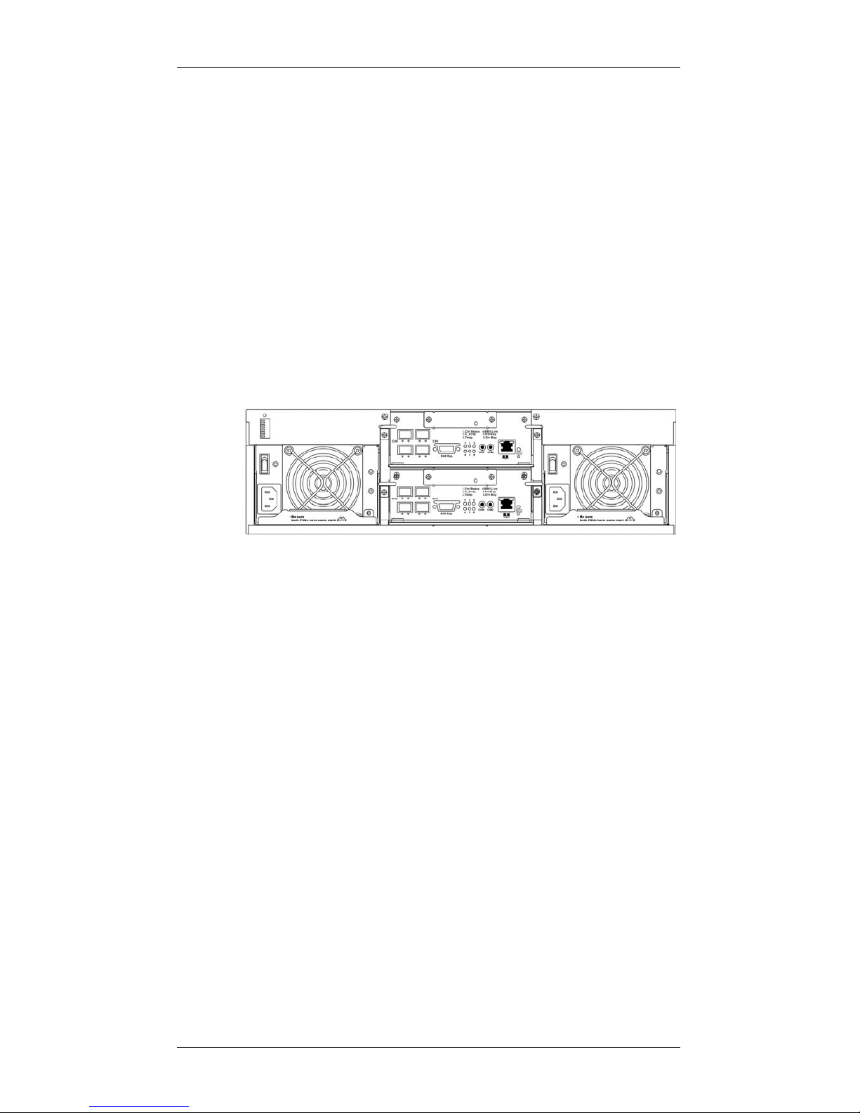
1.2.2 Rear Panel Overview
The rear view of the subsystem is shown below. The rear panel provides
access to all components located in the rear section of the chassis.
Figure 1-3: GHDX2-1430R-16F4D Subsystem Rear View
• RAID controller modules: Each controller module contains a main
circuit board and a pre-installed DDR RAM DIMM module. (See
Section 1.3.3.)
About the dual-redundant RAID controllers in GHDX21430R-16F4D:
For the RAID subsystem featuring redundant RAID controllers, the
upper controller module is identified as Controller A, while the lower
controller module is identified as Controller B. By factory default,
management tools such as the LCD keypad panel, hyper terminal and
RAIDWatch
®
manager recognize Controller A as the primary
controller and Controller B as the secondary controller.
If Controller A fails for any reason (hardware error, software error,
removal from system, etc.), then Controller B will take over and
become the primary/managing controller.
If the failed Controller A restarts and successfully returns to service, it
will temporarily become the secondary controller.

Galaxy GHDXS2-1430R-16F4D Installation and Hardware Reference Manual
1-4 Major Subsystem Components
Once the subsystem is rebooted, all system configurations revert to the
default stage so that Controller A becomes the primary controller and
Controller B the secondary controller.
BBUs: Two (2) BBUs come as standard equipment for the dual-
controller GHDX2-1430R-16F4D. Each BBU sustains cache
memory for days during a power outage to prevent data loss. These
BBUs are hot-swappable. (See Secti on 1. 3. 5 . )
PSUs: The hot-swappable, load-sharing PSUs convert 110V or
240V input to 3.3V, 5V, or 12V for subsystem components.
Subsystem power-on/off is controlled by a power switch on each
PSU. (See Section 1.3.6.) These modules contain the subsystem’s
cooling modules. The redundant cooling modules ventilate the
chassis with an airflow traveling from the front to the rear. (See
Section 1.3.7.)
1.2.3 Integrated Backplane
An integrated backplane board separates the front and rear sections of the
chassis. This circuit board provides logic level signals and low voltage
power paths. Thermal sensors and I
2
C devices are implemented to detect
system temperature and PSU/cooling module presence signals. This board
contains no user-serviceable components.
The backplane board is designed for dual-ported SAS drives. Every disk
drive is connected through two separate SAS domains and each SAS
domain is individually managed by a RAID controller in a dual-controller
configuration.
1.2.4 Physical Dimensions
The RAID subsystem comes in an enhanced 3U chassis with the following
dimensions:
With handles: 488.6mm (W) x 131mm (H) x 504.3mm (L) (19 x
5.2 x 21 inches)
Without handles: 445mm x 130mm x 488.2mm (17.5 x 5.1 x 19.2
inches)
1.3 Major Subsystem Components
Both RAID models house many active components and most of them can
be accessed through either the front or rear panel. The modular enclosure
Chapter 1: Introduction
Major Subsystem Components 1-5
design facilitates the ease of installation and maintenance procedures. Hotswap mechanisms are incorporated to eliminate power surges and signal
glitches that might occur while removing or installing these modules. Each
component is further described below:
1.3.1 LCD Keypad Panel
PN: GAL-9273CHandLLCD
The LCD keypad panel consists of a 2-rows x 16-characters LCD screen
with push buttons and LED status-indicators. The LCD keypad panel
provides full access to RAID configuration utility and monitoring functions.
After powering up the subsystem, the initial screen will display the
subsystem’s model name. A different name can be assigned to the
subsystem for ease of identification in a topology consisting numerous
arrays.
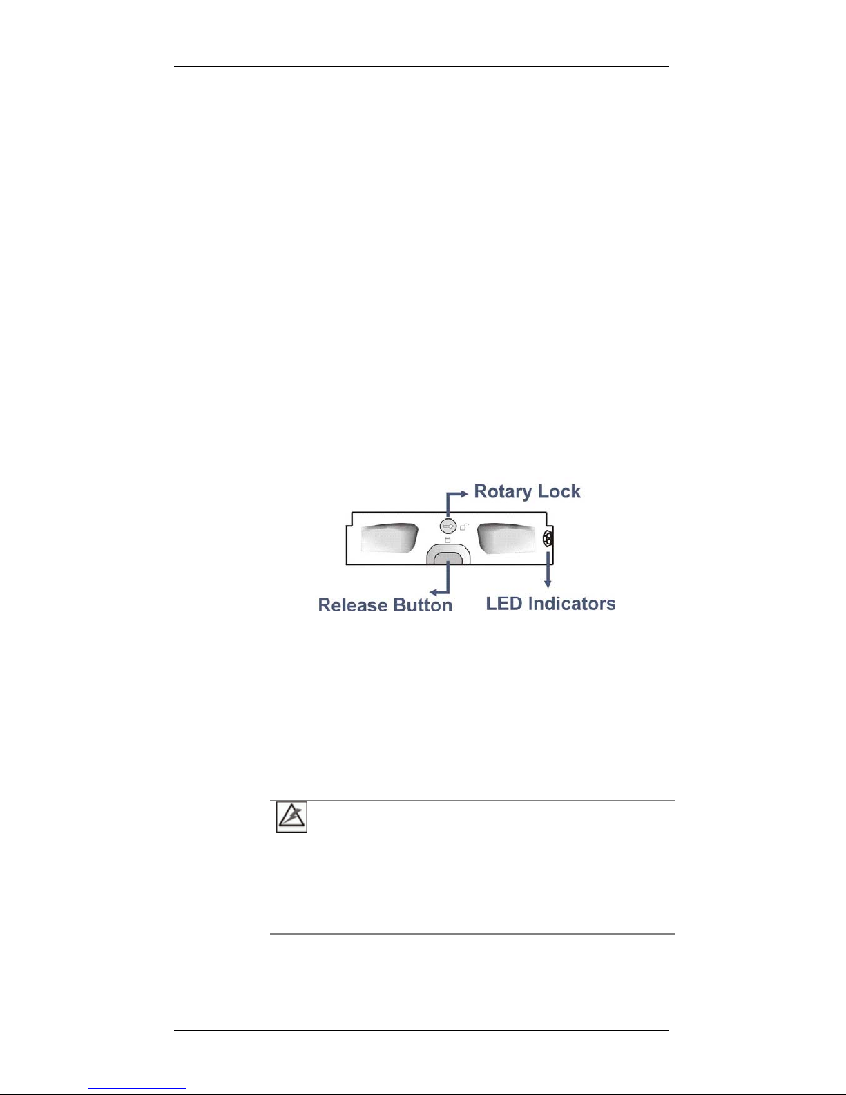
1.3.2 Drive Tray
Figure 1-4: Drive Tray Front View
PN: GAL-9273CDTray
The RAID subsystem comes with sixteen (16) drive trays (see Figure 1-4)
designed to accommodate separately purchased standard 1-inch pitch, 3.5inch SAS/SATA disk drives. Two (2) LEDs on the drive tray’s front bezel
indicate drive status. A rotary bezel lock on each drive tray prevents
unintentional ejection, and a convenient release button releases the drive
tray from chassis.
WARNING!
Be careful not to warp, twist, or contort the drive tray in any way (e.g., by
dropping it or resting heavy objects on it). The drive tray has been
customized to fit into the drive bays in the subsystem. If the drive bay
superstructure is deformed or altered, the drive trays may not properly fit
into the drive bay.
Galaxy GHDXS2-1430R-16F4D Installation and Hardware Reference Manual
1-6 Major Subsystem Components
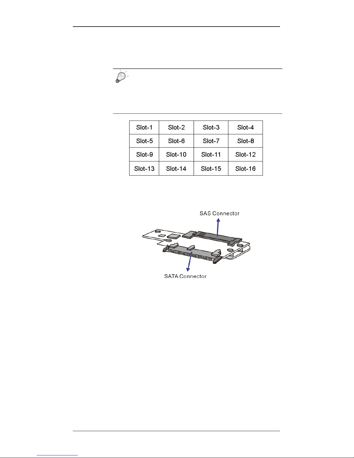
The subsystems are housed in an enclosure that is 4 bays wide and 4 bays
high. When viewing from the front, drive bay IDs ar e numbered from Slot 1
to Slot 16 (see Figure 1-5), from left to right, and then from top to bottom.
TIPS:
Tray numbering sequence is important if one disk drive fails and
needs to be replaced. Replacing a wrong drive can fatally fail a
RAID3/5 array. Failing three drives destroys a RAID6 array.
Figure 1-5: RAID Drive Bay Numbering Sequence
1.3.3 MUX Kit
Figure 1-6: MUX Kit
P/N: GAL-9273S1N2S1S (MUX kit)
GAL-9273S1DT2S1S (Drive tray with a pre-installed MUX kit)
The MUX kit enables partner RAID controllers to access individual SATAII hard drives in a dual-controller configuration. Because of the relatively
high price of the emerging SAS drives, SATA-II disk drives may be a more
popular choice for the moment. As the result, a MUX kit is attached to
every drive tray as the default configuration of the dual-controller model.
The MUX kits are equipped with active-active port selectors to facilitate
SATA drive installation and access from dual-active RAID controllers.
When installed into the enclosure, the SAS connectors on the other end of
the MUX kits will mate with the corresponding connectors on the backplane
board.
Chapter 1: Introduction
Major Subsystem Components 1-7
NOTE:
If the dual-ported SAS hard drives are preferred, there is no n eed for
a MUX kit on each drive tray. The MUX kits should then be
manually removed from each drive tray.
CAUTION!
The MUX kits are small, delicate components that must be handled with
care.
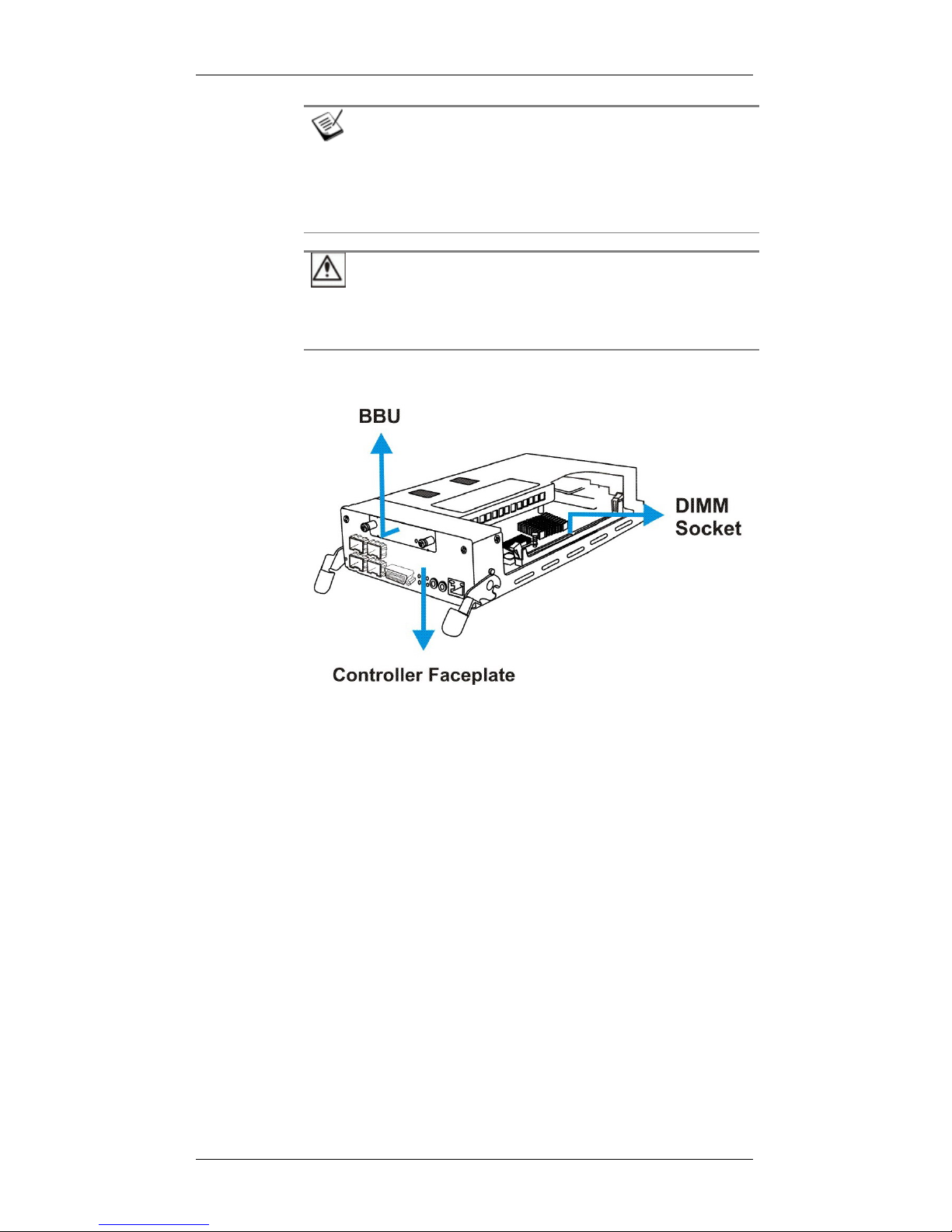
1.3.4 The RAID Controller Module
Figure 1-7: RAID Controller Module
PN: GAL-83SF14RE16 (for RAID-R1430)
The RAID controller module that came with your subsystem contains a
controller board, a BBU adapter board, an interface faceplate, and a preinstalled DIMM module. The BBU adapter board is mounted on top of the
main circuit board and is non user-serviceable. The DDR RAM DIMM
socket is strategically placed on an easily accessible location. (See Figure
1-7) A BBU slot on the top center of the controller module receives a BBU
module.
The controller module contains no user-serviceable components. Except
when installing/upgrading the cache memory inside, the controller module
should never be removed from the chassis.

Galaxy GHDXS2-1430R-16F4D Installation and Hardware Reference Manual
1-8 Major Subsystem Components
WARNING!
Although the RAID controller can be removed, the only time you should
touch the controller itself is to install/upgrade the memory modules. The
RAID controller is built of sensitive components and unnecessary
tampering can damage the controller.

Chapter 1: Introduction
Major Subsystem Components 1-9
Docking Connectors: The FCI docking connectors at the rear of the
controller boards connect the controller module to the backplane board.
Ejection levers: The two (2) ejection levers on the sides of the
controller canister ensure positive connection and provide a graceful
means to retrieve the canister from chassis.
1.3.4.1 JBOD Support
JBOD Enclosure Service:
Each RAID controller comes with a SAS 4x, wide expansion port that
connects to SAS JBOD(s). A managing RAID subsystem is aware of
the operating statuses of JBOD components including:
1. JBOD expander controller
2. PSU
3. Cooling module
4. Enclosure thermal
5. Disk drives
A managing RAID subsystem acquires JBOD component statuses via a
proprietary enclosure service using in-band SAS port connectivity. No
additional management connection is required.
JBOD Identifier:
The managing RAID subsystem will sound the alarm and deliver
notification messages if the following occur:
1. JBOD ID conflict. If more than one JBOD is connected to
the managing RAID subsystem, each JBOD needs a
unique ID set by the rotary switch on the chassis ear.
2. Firmware automatically disconnects a second JBOD if the
second JBOD is connected online and comes with an ID
identical to that of the first JBOD.
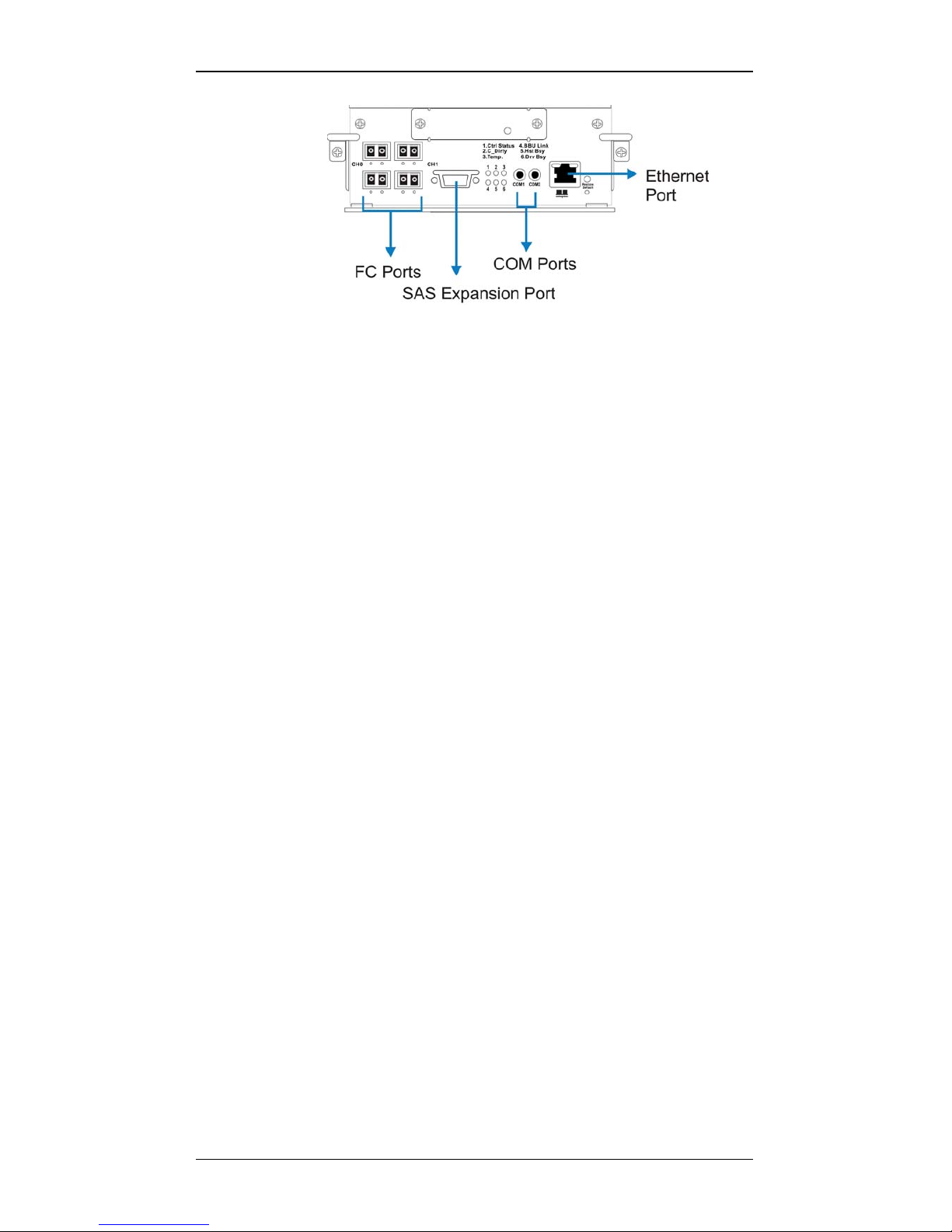
1.3.4.2 Controller Module Interfaces
The controller interfaces are accessed through the controller’s rear-facing
faceplate shown in Figure 1-8.
Galaxy GHDXS2-1430R-16F4D Installation and Hardware Reference Manual
1-10 Major Subsystem Components
Figure 1-8: RAID Controller Faceplate
4G FC host ports: Each controller module has four (4) FC ports with
the onboard hub functionality, two (2) for each Fibre Channel. Each
host port comes with two (2) LEDs to indicate link and speed statuses.
Two (2) 4G FC host channels, CH0 and CH1, connect the subsystem to
the host computers equipped with 4G FC connectivity. The Fibre
Channel host ports receive 4.25/2.125GBd SFP, LC duplex type
transceivers and then connect to LC-type optical fiber cables.
SAS SFF-8470 Expansion Port: This SAS expansion port allows you
to expand the raw capacity of your RAID subsystem with 3 (to dualcontroller RAID) add-on JBODs. For more information, please refer to
the documentation that came with the S16S-J1000 series expansion
enclosures or Section 3.3 of this manual.
COM ports: Each controller module comes with two (2) serial ports.
The COM1 port is used for accessing the controller-embedded
configuration utility through a RS-232C serial connection and over a
VT-100 terminal emulation program running on a management
computer. A dual-audio-jacks-to-DB9 Y-cable for the RAID-R1430 is
included with the shipping package.
The second COM port, marked as COM2, is for connecting to an
uninterruptible power supply (UPS). An optional audio-jack-to-DB9
cable (PN: GAL-9270CUPSCab or GAL-9270CUPSYCab) is available
for purchase.
Ethernet port: All controller modules on the RAID come with a
10/100BaseT Ethernet port that can be used for local/remote
management. When operated in the dual-active mode, system
configuration is handled through one of the controllers. In the event
when one controller fails, the Ethernet port on the surviving controller
inherits the configured IP and continues the monitoring or
configuration session. Shielded cables are recommended to protect
against emissions. Connect the other end of the Ethernet cable to a
LAN port of your local network.

Chapter 1: Introduction
Major Subsystem Components 1-11
LED indicators: Each controller’s interface faceplate comes with
numerous LED indicators. Please refer to Chapter 4 for information on
the LED definitions.
Restore Default Button/LED: Pressing the “restore default button”
while powering on the subsystem will restore firmware defaults.
CAUTION!
The Restore NVRAM Default push button is a function that carries some
risks. Firmware restoration will not destroy the existing logical drive
configurations; however, if the existing logical drives cannot be
adequately associated with host ID/LUNs after firmware default
restoration, data loss or inconsistencies may occur.
The “Restore Default” button is a non-latch type push button
accessed through a round opening underneath the Restore Default
LED.
Listed below are the necessary procedures that should be
completed before using this button:
1. Before pressing this button to restore firmware defaults, it is
highly advised to make a list of the existing ID/LUN mapping
information. You will need the list for restoring ID/LUN
mapping after restoring defaults. Default restoration will erase
the ID/LUN mapping associations (e.g., which logical drive is
associated with which host ID/LUN), and it is necessary to
restore the host ID/LUN mapping after firmware default
restoration in order to access data on the previously configured
arrays.
2. Some of the latest firmware updates may be incompatible with
the firmware currently running on your subsystem. These
updates may require restoring firmware defaults before
firmware upgrade can actually take place. Before using the
button, it is highly advised to practice the following:
Stop host I/Os,
Backup your data,
Make a list of host ID/LUN mapping information for
future references.
It is also recommended to keep a record of all
configuration parameters such as the performance
preferences, specific stripe sizes, etc., using the
“Save NVRAM” firmware function.
3. Another condition that requires restoring defaults is when an
administrator forgets the password configured to control the
access to a RAID subsystem. Before pushing this button, also

Galaxy GHDXS2-1430R-16F4D Installation and Hardware Reference Manual
1-12 Major Subsystem Components
practice the steps listed above. You can access array
information even without a password.
How to use the button?
After the subsystem is powered down, you can use a straighten paper-clip
to press the button. Press and hold the button while powering on the
subsystem, and wait for the associated LED and system Ready LED to light
up. The “Restore Def.” LED indicates successful restoration of firmware
defaults.
With redundant RAID controllers, the procedure can be tricky:
Step 1. Remove one controller from the subsystem, power down,
and then power on with the “Restore Def.” button depressed
to restore the firmware defaults on the remaining controller.
Step 2. Power down, and remove the controller you previously
restored its defaults.
Step 3. Install the controller you have not configured, and repeat
the restoration process.
Step 4. When completed with restoring defaults on both controllers,
power down, install both controllers, and power on.
1.3.4.3 DIMM Module
Each controller module comes with a DDR RAM DIMM module.
The 184-pin DDR RAM DIMM socket comes with a pre-installed 512MB
capacity or above DDR RAM DIMM and is able to support a module with
up to 2GB capacity.
The DIMM module is accessed through an opening on the side of the
controller canister. If the need should arise for replacing the DIMM module,
please refer to Chapter 5 for details on upgrading/replacing DIMM
modules.
Chapter 1: Introduction
Major Subsystem Components 1-13
1.3.5 BBU
Figure 1-9: BBU
PN: GAL-9273CBTE
The Li-Ion BBU module, a shown above, can sustain cached data for days
during a power failure. The use of a BBU is highly recommended in order
to ensure data integrity. If power outage occurs, the BBU supplies power to
sustain the unfinished writes cached in memory. The BBU module is hotswappable.
Galaxy GHDXS2-1430R-16F4D Installation and Hardware Reference Manual
1-14 Major Subsystem Components
New Feature:
The battery cell packs come with an EEPROM to record the date of
installation; and when the approximate one-year life expectancy is reached
(by checking against the real-time-clock), system administrators will be
notified for replacing the BBU.
In accordance with international transportation regulations, the BBU is only
charged to between 35% and 45% of its total capacity when shipped. After
powering on the subsystem (see Section 4.1) the BBU will automatically
start charging its battery cells. It usually requires approximately seven (7)
hours for the battery to be fully charged.
If the battery is not fully charged after twelve (12) hours, a problem might
have occurred with the BBU and you should contact yo ur subsyste m vendor
for a replacement. Re-installing the BBU may sometimes correct the fault if
BBU charger has overheated and forced the charging process to halt many
times during the charging process. If the overheating conditions occurred
during the process, charge time must extend the expected twelve hours.
While charging the battery, the LED on the BBU will flash slowly. You can
check battery charge using the RAIDWatch management software or
firmware configuration utility.
WARNING!
The BBU is hot-swappable itself; however, when the controller module is
removed from the subsystem, the BBU is also removed. Do not remove
the controller module unless it becomes absolutely necessary.
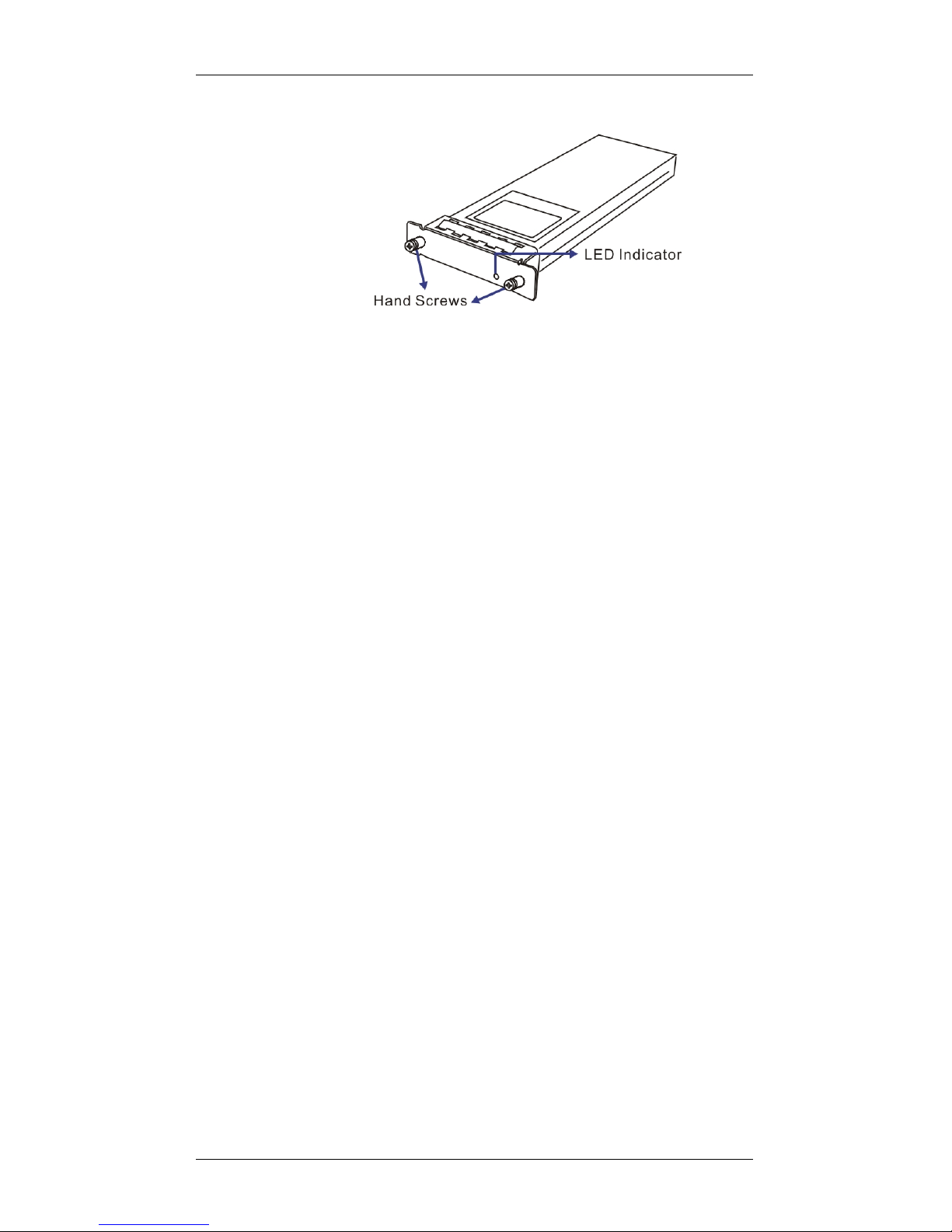
1.3.6 PSUs
Figure 1-10: PSU Components
PN: GAL-9273ECPSU
The subsystem is equipped with two (2) redundant, hot-swap pable, 530W
PSUs, which are located at the rear of the enclosure. The PSU is
Chapter 1: Introduction
Major Subsystem Components 1-15
permanently mounted into a 2U bracket especially designed to house both
the PSU and a cooling module. If a PSU is removed from the chassis, the
cooling module within is also removed.
As shown in Figure 1-10, each PSU comes with a single power socket for
power cord plug-in and a power switch to turn the subsystem on and off. A
single LED indicates the PSU status. For the LED definitions, please refer
to Section 4.4.9. If a PSU fails the LED lights steadily red. An ejection
handle on the PSU enables you to remove or to secure the PSU in place.
This should only occur if the PSU fails and needs to be replaced.
In addition to the ejection lever, a retention screw fastened through a hole
on the ejection handle helps prevent accidental disconnection.
For the PSU specifications, please refer to Appendix A.4.
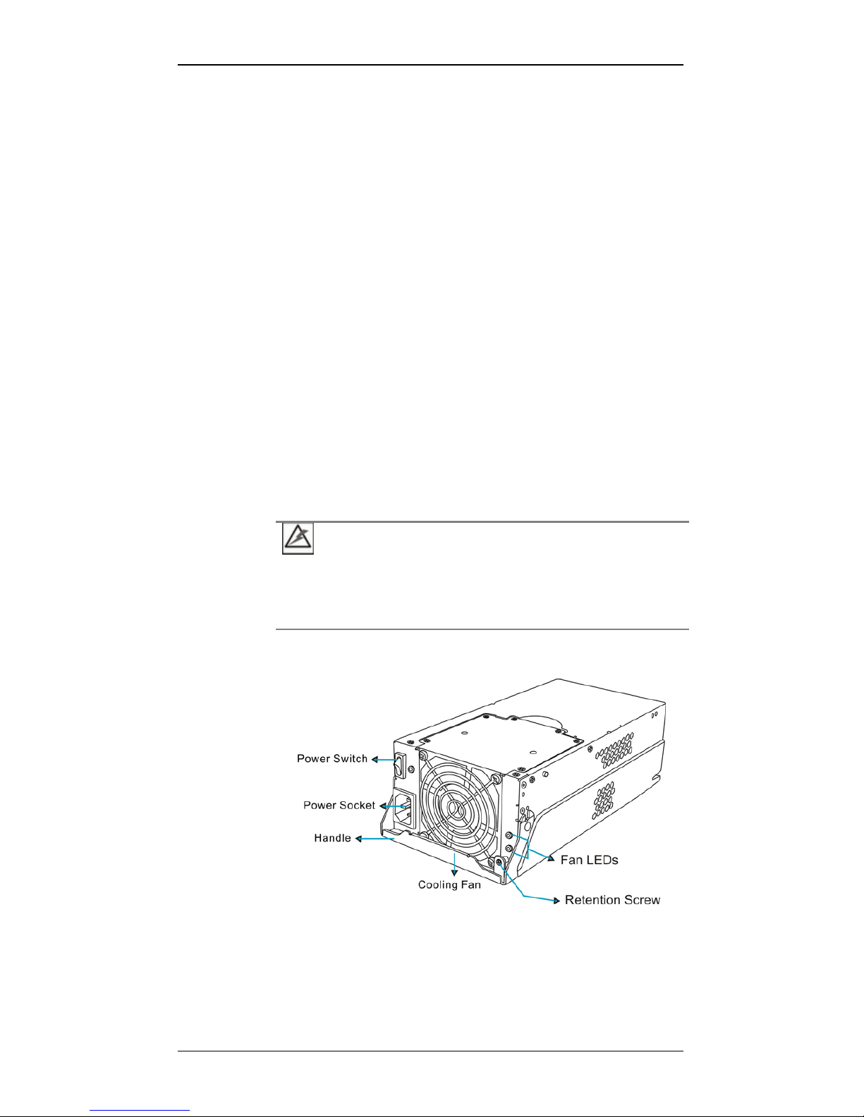
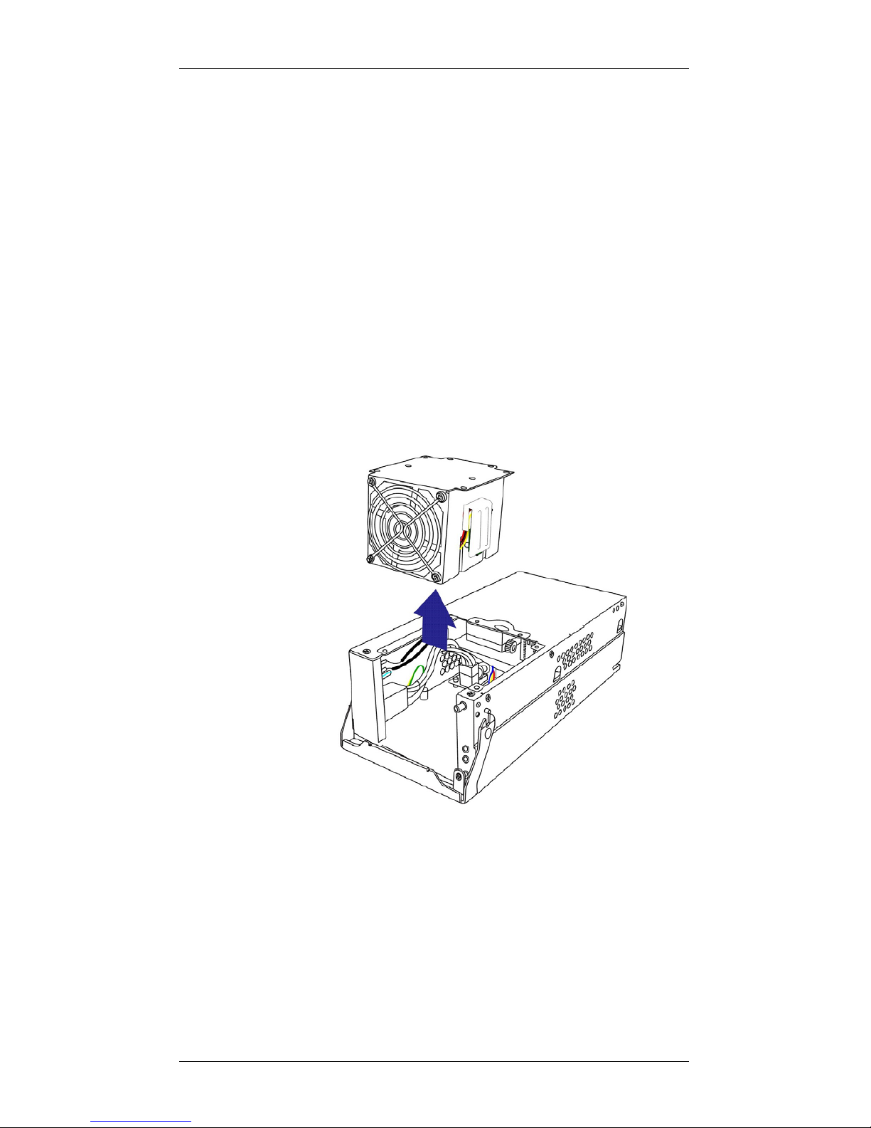
1.3.7 Cooling Modules
Figure 1-11: Cooling Module
PN: GAL-9273ECFanMod
The subsystem is equipped with two (2), dual-fan, redundant cooling
modules. They are installed in the rear section of the PSU modules. Two (2)
LEDs on the PSU faceplate indicate the cooling fan status.

Galaxy GHDXS2-1430R-16F4D Installation and Hardware Reference Manual
1-16 Subsystem Monitoring
Intelligent Dual Speed Operation
The cooling fans in the cooling module operate with two rotation speeds.
Under normal conditions, the cooling fans run at the low speed, which is
sufficient for maintaining airflow across components. Under the following
conditions, cooling fans raise their rotation speed to increase airflow:
1. Component Failure: if one cooling fan, a PSU, or a temperature
sensor fails, the remaining cooling fans automatically raise its
rotation speed.
2. Elevated Temperature: if the temperature reading breaches the
upper threshold set for any of the interior temperature sensors, the
cooling fans automatically raise its rotation speed.
3. During the subsystem initialization stage, the cooling fans operate
at the high speed and return to lower speed once the initialization
process is completed and that the subsystem has not discovered
any erroneous conditions.
1.4 Subsystem Monitoring
The RAID subsystem comes with a number of different monitoring
approaches that provide you with continual updates on the status of the
subsystem and individual components. The following monitoring features
are provided with the subsystem.
1.4.1 I2C bus
The following RAID subsystem elements are interfaced to the RAID
controller over a non-user-serviceable I
2
C serial bus:
• PSUs
• Cooling modules
• Temperature sensors (for the RAID controller board and backplane
board)
• Module presence detection circuits
1.4.2 LED Indicators
The following active components come with LEDs to indicate the status of
individual components. Please refer to Chapter 4 for more information on
System Monitoring.
• LCD keypad panel (3 LEDs)

Chapter 1: Introduction
Subsystem Monitoring 1-17
• Drive trays (2 LEDs on each tray)
• RAID controllers, each module has
− 10 Ethernet port Link and Speed LEDs
− 6 controller status LEDs
− 1 Restore Default LED
• BBUs (1 LED on each module)
• Cooling modules (2 LEDs on PSU canister)
• PSUs (1 LED on PSU canister)
1.4.3 Firmware (FW) and RAIDWatch GUI
Firmware: The firmware (FW) is pre-installed software used to configure
the subsystem. The FW can be accessed either through the LCD keypad
panel or a terminal emulation program running on a management computer
that is connected to the subsystem’s serial port.
RAIDWatch: RAIDWatch is a premier, browser-based or Java-based
graphical user interface (GUI) that can be installed on a remote computer
and accessed via the web. The manager communicates with the array via the
connection of the existing host interface or Ethernet link to the array’s
Ethernet port.
1.4.4 Audible Alarms
The RAID subsystems come with audible alarms that are triggered when
certain active components fail or when certain controller or subsystem
thresholds are exceeded. Whenever you hear an audible alarm from an
RAID subsystem, it is imperative that you determine the cause and rectify
the problem immediately.
Event notification messages indicate the completion or status of array
configuration tasks and are always accompanied by two (2) or three (3)
successive and prolonged beeps.
CAUTION!
Failing to respond when an audible alarm is heard can lead to permanent
damage of the RAID subsystem. When an audible alarm is heard, rectify
the problem as soon as possible.
 Loading...