

Page 1

i
GALaxy eHydro
Elevator Controller Manual
GAL Manufacturing Corporation LLC
50 East 153rd Street
Bronx, NY 10451
Technical Support: 1‐877‐425‐7778
Page 2

ii
Foreword
GAL Manufacturing has developed this manual with usability and safety in mind. General and specific
safety notices and precautions are defined in the manual.
However,
GAL Manufacturing cannot be
responsible for any injury to persons or damage to property (including the elevator equipment) resulting
from negligence, misuse of the equipment, misinterpretation of instructions included in this manual, or
due to any other cause beyond the control of GAL Manufacturing.
All drawings, illustrations, and information herein are the property of GAL Manufacturing and must not
be made public or reproduced by any individual or entity other than the purchaser hereof without the
express written permission of GAL Manufacturing.
Revision 7.1
GAL Part Number: DOC-0119N
Page 3

iii
GALaxy eHydro Controller Manual………………………………………………………………………………i
Foreword...…………………………………………………………………………………………………………...ii
Table of Contents………..…………………………………………………………………………………………iii
Section 1 - Product Description ........................................................................................................... 1-1
1.1 Product Code Compliance ......................................................................................................... 1-1
1.2 Specifications ............................................................................................................................. 1-1
1.3 Physical Layout of the Controller ............................................................................................... 1-2
1.4 Selector System ......................................................................................................................... 1-3
1.4.1 Absolute Position System (APS) Selector .......................................................................... 1-3
1.4.2 Primary and Secondary Position Feedback ....................................................................... 1-4
1.5 Sequence of Operation .............................................................................................................. 1-5
1.6 Modes of Operation .................................................................................................................... 1-6
1.6.1 Reset Mode ........................................................................................................................ 1-6
1.6.2 Safety String Open Mode ................................................................................................... 1-6
1.6.3 Controller Inspection Mode ................................................................................................ 1-6
1.6.4 Car Top Inspection Mode ................................................................................................... 1-6
1.6.5 Access Mode ...................................................................................................................... 1-7
1.6.6 Independent Service Mode ................................................................................................ 1-7
1.6.7 Load Weighing Bypass Mode ............................................................................................ 1-7
1.6.8 Attendant Service Mode ..................................................................................................... 1-8
1.6.9 Code Blue Hospital Service Mode ..................................................................................... 1-8
1.6.10 Fire Service Phase I Mode ................................................................................................. 1-8
1.6.11 Fire Service Phase I Alternate Return Mode...................................................................... 1-9
1.6.12 Fire Service Phase II Mode ................................................................................................ 1-9
1.6.13 Emergency Power Sequencing .......................................................................................... 1-9
1.6.14 Emergency Power Battery Lowering ................................................................................ 1-10
1.6.15 Earthquake Mode ............................................................................................................. 1-10
1.6.16 Stalled (Low Oil) Mode ..................................................................................................... 1-10
1.6.17 Automatic Mode ............................................................................................................... 1-10
Section 2 - Installation .......................................................................................................................... 2-1
2.1 General Information.................................................................................................................... 2-1
2.2 Site Selection ............................................................................................................................. 2-1
2.3 Environmental Considerations ................................................................................................... 2-1
2.4 Wiring Guidelines and Instructions ............................................................................................. 2-1
2.4.1 Wiring Schematics .............................................................................................................. 2-2
2.4.2 Proper Field Wiring ............................................................................................................. 2-2
2.4.3 Ground Wiring .................................................................................................................... 2-2
2.4.4 Hoistway Wiring .................................................................................................................. 2-2
2.4.5 Elevator Car Wiring ............................................................................................................ 2-3
2.4.6 Machine Room Wiring ........................................................................................................ 2-3
2.5 Normal and Top Terminal Slowdown Limits .............................................................................. 2-3
2.6 Top Terminal Limit Switches ...................................................................................................... 2-4
2.7 Selector Installation .................................................................................................................... 2-4
2.7.1 APS (Absolute Position System) Selector Installation ....................................................... 2-4
2.7.1.1 Installation of the Encoded Tape and APS Camera ...................................................... 2-4
2.7.2 APS Selector Floor Position Setup (Hoistway Learn) ...................................................... 2-14
2.7.2.1 Verify that the APS Selector Camera is Installed Correctly and Communicating. ....... 2-14
2.7.2.2 Set the Adjustable Variables – “NTS Proc Adj Vars” in the Controller. ........................ 2-15
2.7.2.3 Zero the Hoistway ........................................................................................................ 2-15
2.7.2.4 Setting Hoistway Floor Levels with APS Selector ........................................................ 2-16
Section 3 - GALaxy Startup and Adjustment ...................................................................................... 3-1
3.1 Procedure for Initial Power-up of Controller ............................................................................... 3-1
3.1.1 Checking Main Line Voltage............................................................................................... 3-1
Table of Contents
Page 4

iv
3.1.3 Verify the Main CPU is Operating ...................................................................................... 3-1
3.2 Start-Up Procedures................................................................................................................... 3-2
3.2.1 Requirements for a running platform during initial startup ................................................. 3-2
3.2.2 Complete the Installation of Equipment ............................................................................. 3-4
3.3 Adjustment Procedures .............................................................................................................. 3-5
3.3.1 Set Toggle Switches ........................................................................................................... 3-5
3.3.2 Ready the Car to Run on Inspection .................................................................................. 3-5
3.3.3 Prepare for the Car for Hoistway Learn ............................................................................. 3-6
3.3.4 Verify the Hoistway ............................................................................................................. 3-7
3.4 Adjust the Elevator ..................................................................................................................... 3-7
3.4.1 Automatic Run .................................................................................................................... 3-7
3.4.2 Adjust the Slowdown Distances ......................................................................................... 3-8
3.4.3 Adjust the Stop ................................................................................................................... 3-9
3.4.4 Verify Proper Operation of All Safety Circuits and Signal Devices .................................. 3-10
3.4.5 Perform Required Tests ................................................................................................... 3-10
Section 4 Troubleshooting ................................................................................................................... 4-1
4.1 General Information.................................................................................................................... 4-1
4.2 Microprocessor CPU .................................................................................................................. 4-1
4.3 Input/Output Boards ................................................................................................................... 4-1
4.4 Run Sequence ............................................................................................................................ 4-2
4.5 The Safety PAL Functions ......................................................................................................... 4-3
4.6 Safety PAL ................................................................................................................................. 4-5
4.7 System Faults ............................................................................................................................. 4-6
4.8 Main CPU Inputs and outputs .................................................................................................... 4-6
4.9 NTS Processor Inputs and Outputs ......................................................................................... 4-11
4.10 Relocate I/Os ............................................................................................................................ 4-12
4.10.1 Relocate I/Os – Add IO Relocation .................................................................................. 4-13
4.10.2 Relocate I/Os – Remove Relocation IO ........................................................................... 4-14
4.10.3 Car Trace Screen ............................................................................................................. 4-15
Section 5 LCD Interface ........................................................................................................................ 5-1
5.1 Operating the LDC Interface ...................................................................................................... 5-1
5.2 LCD Menus ................................................................................................................................ 5-2
5.2.1 Elevator Status ................................................................................................................... 5-2
5.2.2 Main Menu ........................................................................................................................ 5-12
5.2.3 Date and Time .................................................................................................................. 5-13
5.2.4 Set Calls and Lockouts ..................................................................................................... 5-14
5.2.5 Inputs and Outputs ........................................................................................................... 5-17
5.2.6 Job Statistics .................................................................................................................... 5-20
5.2.7 Adjustable Variables ......................................................................................................... 5-21
5.2.8 Diagnostics ....................................................................................................................... 5-22
5.2.9 Software Utilities ............................................................................................................... 5-29
5.2.10 Hoistway Tables ............................................................................................................... 5-33
5.2.11 Fault Log........................................................................................................................... 5-39
Section 6 - Main CPU Faults & Detailed Faults ................................................................................ 6-40
6.1 Main CPU Faults ...................................................................................................................... 6-40
6.2 Device Fault in Fault Log ......................................................................................................... 6-84
6.3 Detailed Faults Data and Description....................................................................................... 6-99
6.3.1 Detailed Fault I/O Data Example .................................................................................... 6-112
6.3.2 Detailed Fault I/O Data Form ......................................................................................... 6-115
Section 7 - Main CPU Adjustable Variables ........................................................................................ 7-1
Section 8 - Appendix A ......................................................................................................................... 8-1
8.1 Testing Stall Mode & Low Oil Operation .................................................................................... 8-1
8.2 Reset Low Oil, Hot Oil, or MC/SPD Fault................................................................................... 8-2
8.3 Performing a Stop Ring Test ...................................................................................................... 8-2
Page 5

v
8.4 Testing NTSD ............................................................................................................................. 8-2
8.5 Testing Terminal Speed Reducing Device ................................................................................. 8-3
8.6 Testing the Load Weighing Device ............................................................................................ 8-3
8.7 Testing Phase 2 Operation With a Ground or Short Circuit ....................................................... 8-3
8.8 Testing Phase 1 & 2 Operation After Power Interruption and Restoration ................................ 8-3
8.9 Testing Recycling Operation ...................................................................................................... 8-4
8.10 Testing Plunger Gripper Operation ............................................................................................ 8-4
8.11 Testing Phase 1 Operation Under Special Conditions ............................................................... 8-4
8.12 Testing Phase 2 Operation Under Special Conditions ............................................................... 8-5
8.13 Testing Plunger Following Guide Protection .............................................................................. 8-6
8.14 Testing the Auxiliary Power Supply With the Disconnect Switch Open ..................................... 8-6
8.15 Testing Low Pressure Switch ..................................................................................................... 8-6
8.16 Testing Low Pressure Switch ..................................................................................................... 8-6
Page 6
vi
SYMBOLS USED IN THIS MANUAL
CAUTION
This manual uses the CAUTION symbol to identify procedures and practices that may result
in personal injury and/or equipment damage, if not followed correctly.
DANGER
This manual uses the DANGER symbol as an alert to a danger of electrocution or an acute
electrical shock. The DANGER symbol provides elevator personnel with a warning of
severe personal injury or potential fatality that can result if safety precautions are not
observed.
NOTE / INFORMATION
In this manual, this symbol identifies information helpful to elevator personnel when carrying
out a specific procedure or task.
NOT APPLICABLE / DOES NOT EXIST
When this symbol appears inside a table, it indicates that a value or property is not defined,
or is nonexistent, for the item listed.
Page 7
vii
WARNINGS AND CAUTIONARY NOTES
Installation and wiring must be in accordance with the national electrical code, all local
codes, and all elevator safety codes and standards. The 3‐phase AC power supply to
the equipment must originate from a properly fused disconnect or circuit breaker that is
properly designed and sized for the specific controller requirements and the “Short
Circuit Current Rating” listed on the controller. Improper motor branch circuit
protection will void warranty and may create a hazardous condition.
Wiring to the controller terminals must be installed in a careful, neat manner. Stranded
wire conductors must not have strands left out of the terminals. Leaving strands of wire
out of the terminals can create a potential short circuit. All terminals and cable
connectors must be seated properly. (See the IMPORTANT notice on the next page.)
Elevator control products must be installed by elevator personnel who have been
trained in the construction, maintenance, repair, inspection, and testing of elevator
equipment. The elevator personnel must comply with all applicable safety codes and
standards. This equipment is an O. E. M. product designed and manufactured to
comply with ASME A17.1-2016/CSA B44-16 Safety Code for Elevators and Escalators.
It is the responsibility of the installer to ensure that the installation is performed safely
and that the installation complies with all applicable codes.
Proper grounding is vitally important to the safe and successful operation of this
system, and proper grounding should be installed to comply with all applicable codes.
A separate ground wire should be installed from the building earth ground to the earth
ground terminal in each controller. Proper conductor size must be utilized for
grounding. In order to minimize resistance to ground, the shortest possible length
should be used for the ground conductor.
Do not install the controller in a hazardous area where excessive vapors and chemical
fumes are present. Do not install the controller in a dusty area. Do not install the
controller in a carpeted area. The space in which the controller equipment is installed
should be temperature controlled, moisture free, and should be maintained within a
temperature range of 32° F and 110°F. The space in which the controller equipment is
installed should be kept clean. The controller should be kept dry and should not be
exposed to moisture or water condensation. Make sure the power supply voltage
feeding the controller equipment does not fluctuate by more than +/- 10%.
Every safety precaution, whether or not specifically stated in this document, must be
implemented when installing, adjusting, or servicing elevator equipment. All safety
precautions must be followed to ensure the safety of elevator personnel and the general
public.
Use only the correct rated fusing for controller protection. Use of improperly rated
fusing will void the warranty.
Page 8
viii
IMPORTANT NOTICE
Most of the field connections to GALaxy controls are made using stranded wire. When inserting this stranded
wire into the terminals – especially those for EPD’s (Electrical Protective Devices) – care must be taken to
ensure that all the strands are properly inserted into the terminals. Improper stripping and insertion may leave
strands outside of the terminals. Strands not properly inserted into the terminals may make contact with wires
from an adjacent terminal.
The danger associated with an occurrence as described above has led GAL Manufacturing to recommend that,
for all connections to the Electrical Protective Devices listed in ASME A17.1-2016/CSA B44-16, Requirements
2.26.2.1 through 2.26.2.39, elevator personnel must follow the guidelines listed below:
• Inspect all terminals used to connect Electrical Protective Devices. Ensure that the cage clamp is fully
open before inserting a wire into the terminal block.
• Perform corrective action for wires with stray strands by one of the following methods:
o Reconnect the wire with all wire strands correctly installed into the terminal. Visually verify that
no wire strands are outside of the terminal. The conductor should be stripped and inserted
completely into the terminal in such a manner that no more than two millimeters of bare wire is
visible; or
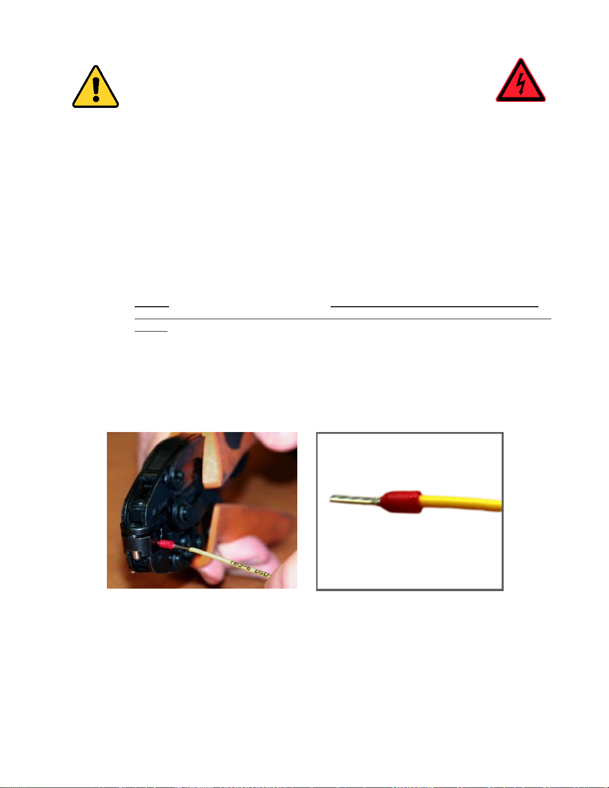
o Attach a ferrule to the end of field wire for safety devices (as pictured below in Figures 0-1 and
0-2) and insert the ferrule into the terminal; or
o Use an acceptable method such as tinning.
• After removal and replacement of any of these field wires, the actual Electrical Protective Device
should be checked for proper operation.
Figure 0-1
Crimp Tool for Ferrule
Figure 0-2
Stranded Wire with Ferrule
Attached
Page 9

GALaxy eHydro Elevator Controller Section 1 – Product Description
1-1
Section 1 - Product Description
The GALaxy traction elevator controller is a computer-based system that offers superior performance,
flexibility and reliability. It has been designed to save time in installation and troubleshooting, but it is still
very important that the field personnel familiarize themselves with this manual before attempting to
install the equipment.
1.1 Product Code Compliance
• CSA B44.1-14/ASME A17.5-2014
• ASME A17.1-2016/CSA B44-16
1.2 Specifications
Standard Features:
• Inspection Operation (car top and controller)
• Access Operation
• Independent Service
• Fire Service Phase I
• Fire Service Phase I Alternate Return
• Fire Service Phase II
• Emergency Power
• Earthquake Service
• On Board Diagnostics LEDs
• On Board LCD Interface
• Motor Protection Timers
• Door Motor Protection Timer
• Field Adjustable Parameters
• Elevator Duty Rated NEMA Motor
Environment:
• 32° F to 110° F ambient
• 12,000 feet altitude
• 95% humidity
Optional Features:
• Selective Rear Doors
• Attendant Service
• Code Blue Hospital Service
• Security
• Remote Diagnostics
• Emergency Power
Page 10

GALaxy eHydro Elevator Controller Section 1 – Product Description
1-2
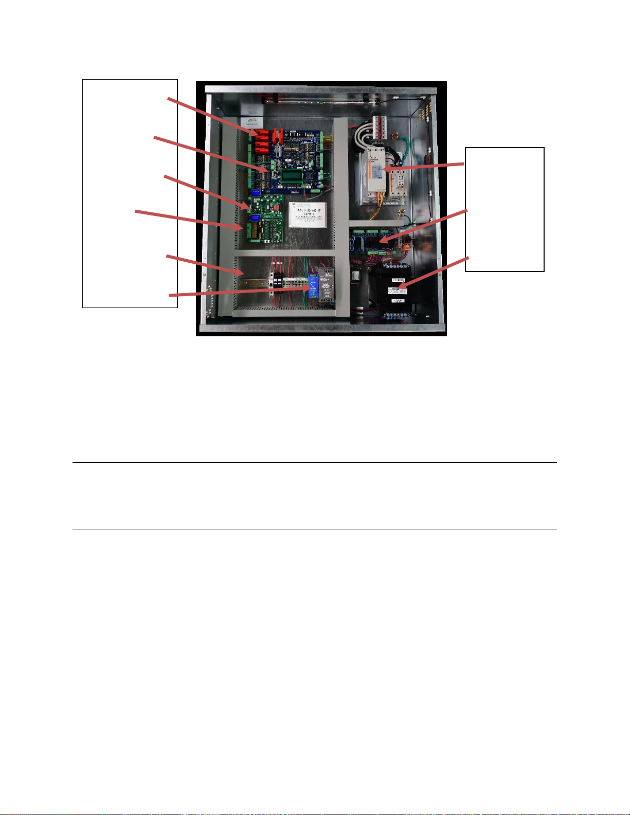
1.3 Physical Layout of the Controller
Figure 1-0 shows the general layout of the GALaxy eHydro Controller cabinet. The components in the
cabinet include the following items.
1) Main I/O Board:
The 1121 main control board contains input and output
devices, controller switches, fuses and field wiring
terminal connections. This board also includes the, the
Safety PAL and the NTS Processor.
2) Main CPU:
The 1132 CPU board is a dual core 32-bit CPU. It
executes the main control system programs. The main
core runs the car operation and the secondary core runs
the group operation. The LCD Interface mounted on the
Main CPU provides a user interface to all controller
adjustment and setup parameters. It also shows
diagnostic information.
3) PI Driver Board:
Driver for CE or E-Motive Position Indicator Displays.
4) Car I/O Panel:
Provides space for additional car I/O.
5) Terminal Block and Options:
Space for additional terminal blocks, optional contactors
and circuit breakers.
6) Power Supplies:
A 5 VDC power supply for the controller 5 Volt power and
a 24 VDC supply for all call button and lantern power.
7) Soft Starter:
Controls the soft start and running of the pump motor.
8) Power Distribution Board:
Contains fuses and distributes 120 VAC and 24 VDC for
the system.
9) Transformer:
Transforms the line voltage to the proper voltages for
signals and other controller functions.
Page 11
GALaxy eHydro Elevator Controller Section 1 – Product Description
1-3
Figure 1-0: Typical Physical Layout of Top Cabinet
1.4 Selector System
The selector system for the GALaxy controller is an Absolute Position System with an encoded
touchless tape.
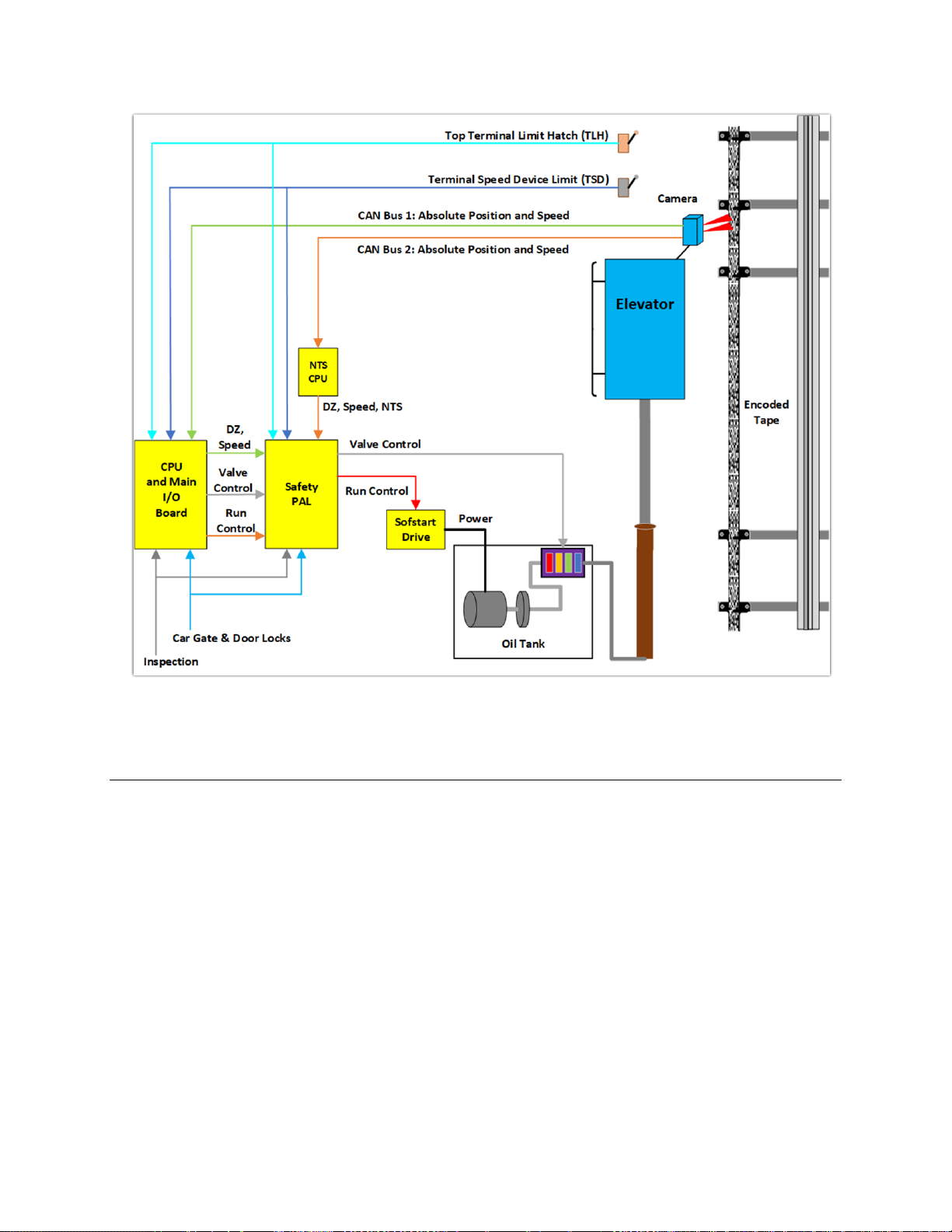
1.4.1 Absolute Position System (APS) Selector
The Absolute Position System Selector uses an encoded tape that is read by two independent
cameras. The dual camera device is SIL3 rated to supply position and velocity data over two
independent CAN bus channels. One CAN bus channel connects directly to the MAIN CPU and the
second CAN bus channels connects directly to the NTS processor. During setup both processors learn
the hoistway floor positions and slowdown limits. Each processor’s outputs control signals and door
zone status to the Safety PAL for independent redundancy checking.
This selector system delivers 0.5mm accuracy, 50.8 pulses per inch. A block diagram of the Absolute
Position System is shown in Figure 1-1.
. 1 Main I/O Board
. Main CPU
2
3
. PI Driver Board
4
. Car I/O
5
. Terminal Block
and Option
Section
6
.
Power
Supplies
7
.
Soft
-
Starter
8 . Power
Distribution
9
. Transformer
Page 12
GALaxy eHydro Elevator Controller Section 1 – Product Description
1-4
Figure 1-1: Absolute Position System Selector
1.4.2 Primary and Secondary Position Feedback
The Main CPU receives position feedback from the channel A camera CAN bus and builds a table of
floor positions and slowdowns for each floor during setup. On a normal run, the Main CPU uses the
slowdown points to initiate a slowdown to the appropriate floor and uses the floor position to determine
the door zone and exact stopping position.
The NTS processor receives position feedback from the channel B camera CAN bus and builds an
independent table of floor door zone positions and normal terminal slowdown limits (UN, UT, DN, and
DT) during setup. On a normal run, the NTS processor uses the NTS slowdown points to
independently remove power from the appropriate run valves as a redundancy to slowdown and stop
the car at terminal landings.
Both the Main CPU and NTS processor outputs door zone and control signals, (SU, SUF, SD, SDF for
the Main CPU and UN, UT, DN, DT for the NTS processor), to the Safety PAL to make hardwarecontrolled decisions that the car is safe to run.
To protect the car from hitting the stop ring at a speed greater than 50 fpm in the up direction, two
mechanical switches are wired in the hoistway at the top terminal landing. The first switch actuated
Page 13

GALaxy eHydro Elevator Controller Section 1 – Product Description
1-5
while running up to the top terminal floor is the Terminal Speed Device (TSD) limit switch that directly
removes power from the up fast valve. The top most limit switch is the Terminal Limit Hatch switch
(TLH) that directly removes power from pump motor and all valves.
1.5 Sequence of Operation
Normal elevator operation, Automatic Mode, is selective-collective. When the elevator is traveling
upwards to answer calls, all up hall calls at floors above the car are answered in the order reached by
the car, regardless of the order in which the calls were registered. Upon reaching each landing with a
car call or hall call registered, the car and hall doors at that floor are automatically opened.
The doors stay opened for a dwell time that is field adjustable. There are three different dwell times
depending on whether it is a lobby call, car call, or hall call. The door will close before the set dwell time
has elapsed if a passenger presses the door close button and the minimum door open time has expired.
The door will reopen before it is fully closed if the door open button is pressed, if a passenger pushes
on the safety edge, if the photo-eye light beam is interrupted, or if a call for that floor in the direction of
travel is pushed. The door will close when the door opening condition is eliminated. When the door has
fully closed, the calls are answered.
When all up hall calls and car calls above the car have been answered, the elevator reverses direction
and travels downward to answer car calls and down hall calls placed below the car. The calls are
answered as previously described for up calls. When all calls below a down car are answered, the car
reverses direction to repeat the cycle. In short, an elevator traveling up will bypass down hall calls, and
an elevator traveling down will bypass up hall calls.
In buildings with more than one elevator grouped together, the actual time of arrival, “real time”, is used
to estimate how long each elevator will take to answer a hall call. The elevator that can respond the
fastest takes the call. Real-time based dispatching permits the controllers to quickly respond to actual
demand for elevator service. Some of the criteria used to estimate the time of arrival are as followed:
• Actual elevator floor to floor run times.
• Actual run time to the floor whether it is a multi-floor run or a one floor run.
• Whether the elevator is in or out of service.
• Whether the elevator is in load weigh bypass mode.
• The direction and position of each elevator in the group.
• The average door cycle time at each stop.
• Status of each elevator, accelerating, full speed, decelerating, actual time in motion.
• Number of stops required due to car calls.
• Number of stops required due to previously assigned hall calls.
• System demand.
The above performance criteria are continuously measured and stored for improved accuracy in the
dispatching algorithm. All of the above data is continuously scanned, and the hall calls are reassigned if
the conditions change and another car can respond faster. The ability to measure actual hall waiting
time virtually eliminates long waiting and improves the average hall call waiting intervals throughout the
building.
Page 14

GALaxy eHydro Elevator Controller Section 1 – Product Description
1-6
1.6 Modes of Operation
1.6.1 Reset Mode
Reset mode is initiated when the elevator power is first turned on, or when the system is reset. When
the reset mode is initiated, the controller performs internal tests to ensure that both the car and
controller are electrically operational before putting the car into service. The car will not move until reset
mode is completed. Some of the internal tests that the controller performs are as follows: is the safety
string made up; is the elevator on inspection operation; is the door close limit open; are the interlocks
made up; is hoistway position correct. If all the safeties are made up, and the elevator is on automatic
operation, and it is at floor level, the elevator will go into automatic mode. If the elevator is not at floor
level, it will run slow speed down to the nearest floor, level into the floor, and reset the floor position
count.
1.6.2 Safety String Open Mode
Safety string open mode is initiated when a safety is open. Some of the safeties are listed below:
• Reverse phase relay
• Governor overspeed switch
• Top Terminal Limit Switch
• Pit switch
• Hatch Safety Switch
• Exit Door Switch
• Car Safeties
• Car top stop switch
• Fire Fighters Stop Switch
• In-Car Stop Switch
• Controller Stop Switch
When the safety string is made back up, the elevator will go back to reset mode.
1.6.3 Controller Inspection Mode
The controller inspection mode is initiated by placing the “INS” switch on the 1121 board in the
inspection position (down). Controller inspection mode permits operation of the car from the machine
room. This mode performs the following operations:
• Enables the controller inspection “ENABLE”, “UP” and “DOWN” push buttons
• Door locks are active and must be closed to move the car.
• Pressing the controller “ENABLE” and “UP” pushbuttons causes the elevator to move at
inspection speed in the up direction.
• Pressing the controller “ENABLE” and “DOWN” pushbuttons causes the elevator to move at
inspection speed in the down direction.
1.6.4 Car Top Inspection Mode
This inspection mode is initiated by placing the inspection switch on top of the car in the inspection
position. Inspection mode permits operation of the car from the car top inspection station. This mode
performs the following operations:
Page 15

GALaxy eHydro Elevator Controller Section 1 – Product Description
1-7
• Disables access top and access bottom hall switches.
• Disables the controller "ENABLE", "UP" and "DOWN" push buttons.
• Door locks and Car gates/locks are active and must be closed or the door lock and gate bypass
switch or switches must be active to move the car.
• Enables the car top inspection station "SAFE", "UP" and "DOWN" push buttons
• Pressing the inspection station "UP" and "SAFE” pushbuttons causes the elevator to move at
inspection speed in the up direction.
• Pressing the inspection station "DOWN" and "SAFE" pushbuttons causes the elevator to move
at inspection speed in the down direction.
1.6.5 Access Mode
The access mode is initiated by placing the key operated access switch located in the car operating
panel to the on position. Access mode allows entrance into the Hoistway by qualified and authorized
elevator personnel for equipment inspection and service. Access to the top of the car is possible from
the top landing, and access to the pit is possible from the bottom landing. Enabling this mode permits
the following operation:
• Enables the access key switches at the top and bottom landing in the entrance door jambs.
• Bypasses the gate switch to allow car movement with the car door open.
• Bypasses the top or bottom landing hall door lock, depending on which terminal access switch
is being keyed.
• Turning the access key switch to the up position causes the elevator to move at access speed
in the up direction.
• Turning the access key switch to the down position causes the elevator to move at access
speed in the down direction.
1.6.6 Independent Service Mode
The independent service mode is initiated by placing the key operated independent switch located in
the car operating panel to the on position, or by placing the controller toggle switch “IND” to the down
position. Independent mode permits operation of the car with an operator. This mode performs the
following operations:
• Hall initiated calls are ignored.
• Hall lanterns and gongs are disabled.
• The doors open automatically and stay open until closed by the operator.
• Closing the doors requires constant pressure on the door close button.
• When the car door is closed, the car answers the nearest car-initiated call in the direction of
travel.
1.6.7 Load Weighing Bypass Mode
The load weighing bypass mode is initiated when the car is loaded to a predetermined percentage of full
capacity, by closing a connection between terminals “LC” and “LW” or from serial communication from a
load weighing device. Load weigh bypass mode allows the car to answer car calls and lighten the load
before answering any more hall calls. This mode performs the following operations:
• Hall initiated calls are ignored.
• All other elevator functions operate as if on fully automatic service.
Page 16

GALaxy eHydro Elevator Controller Section 1 – Product Description
1-8
1.6.8 Attendant Service Mode
The attendant service mode is initiated by placing the key operated attendant switch located in the car
operating panel to the on position. Attendant mode permits operation of the car with an attendant. This
mode performs the following operations:
• The doors open automatically and stay open until closed by the attendant.
• Closing the doors requires a momentary pressure on the door close button, or the up or down
buttons located in the car operating panel.
• Hall initiated calls are answered unless there is constant pressure on the bypass button.
• Hall lanterns and gongs are enabled.
• The direction of preference can be specified by momentary pressure on the up or down buttons
located in the car operating panel.
1.6.9 Code Blue Hospital Service Mode
Code blue hospital service mode is initiated by turning one of the code blue switches, located at each
floor where medical emergency service is required, to the on position. A car is selected to respond to
the code blue call. That car will perform the following:
• Cancel all car calls
• Any hall calls previously assigned will be transferred to another car.
• If traveling toward the code blue call, it will proceed nonstop to the code blue call floor.
• If traveling away from the code blue call, it will slow down and stop at the nearest floor, maintain
doors closed, reverse direction and proceed nonstop to the code blue call floor.
• If at a floor other than the code blue call floor, the elevator will close the doors and proceed
nonstop to the code blue call floor.
• Once at the code blue call floor, the doors will open and remain open.
• The code blue in car switch located in the car operating panel must then be turned to the on
position. If the code blue in car switch is not turned to the on position within 60 seconds from
the time the doors reach full open on the code blue call floor, the car will revert back to normal
operation.
• Upon activation of the key switch, it will allow the car to accept a car call for any floor, close the
doors, and proceed nonstop to the floor desired.
• The return of the code blue in car key switch to the normal position will restore the car to normal
service.
1.6.10 Fire Service Phase I Mode
Fire service phase I is initiated when the primary smoke sensor is activated, or the fire key switch
located in the hall station on the primary return floor is turned to the on position. The primary return floor
is usually the lobby floor but could be another landing if it better serves the needs of emergency
personnel when fighting a fire or performing rescues. When fire service phase I is enabled:
• The fire emergency return light illuminates, and the fire buzzer sounds.
• The emergency stop switch is disabled when the door closes (depending on code requirement).
• The car travels to the primary return floor without answering any calls, then parks with the door
open. The fire buzzer turns off, but the fire emergency return light stays illuminated.
Page 17

GALaxy eHydro Elevator Controller Section 1 – Product Description
1-9
• If the car is at a landing with the doors open, the doors will close, and the car will return non-
stop to the primary return floor.
• If the car is traveling away from the primary return floor, the car will stop at the next landing, and
then go immediately to the primary return floor.
• Turning the fire service key switch to the bypass position will restore the elevator to normal
service.
• The elevator will perform per ASME A17.1 requirement 2.27.3 unless otherwise specified.
1.6.11 Fire Service Phase I Alternate Return Mode
Fire service phase I alternate return is initiated when the smoke sensor in front of the elevator at the
primary return floor is activated. When fire service phase I alternate return is enabled:
• The fire emergency return light illuminates and the fire buzzer sounds.
• The emergency stop switch is disabled when the door closes (depending on code requirement).
• The car travels to the alternate return floor without answering any calls, then parks with the door
open. The fire buzzer turns off, but the fire emergency return light stays illuminated.
• If the car is at a landing with the doors open, the doors will close, and the car will return nonstop
to the alternate return floor. If the car is traveling away from the alternate return floor, the car
will stop at the next landing, and then go immediately to the alternate return floor.
• Turning the fire service key switch to the bypass position will restore the elevator to normal
service.
• The elevator will perform per ASME A17.1 requirement 2.27.3 unless otherwise specified.
1.6.12 Fire Service Phase II Mode
To initiate fire service phase II, the car must first have been placed in fire service phase I, and, as a
result, be parked at the designated level with the door fully open. Following that, the key operated fire
service phase II switch, located in the car operating panel must be placed in the on position. Fire
service phase II permits operation of the car by a fire fighter. This mode performs operations in
accordance with ASME A17.1 requirement 2.27.3 as follows:
• The doors close only with constant pressure on the door close button, after they have been fully
opened.
• The doors open only with constant pressure on the door open button, after they have been fully
closed.
• Hall lanterns and gongs are disabled. Safety edge and electric eye are disabled
• All registered car calls can be canceled with momentary pressure on the call cancel button
located in the car operating panel.
• All hall calls are disabled.
• To remove the car from fire service phase II the car must be at the fire return landing with the
doors in the fully open position and the phase II switch turned to the off position.
• See ASME A17.1 requirement 2.27.3 for specific operation of fire service phase II.
1.6.13 Emergency Power Sequencing
Emergency Power is initiated when a connection is made between terminals “HC” and “EMP”. This
mode performs the following operations:
• All cars are returned to the bottom floor one at a time, and cycle the door.
• The door open button remains active.
Page 18

GALaxy eHydro Elevator Controller Section 1 – Product Description
1-10
• If a car is selected to run it will go back into normal operation.
• Removing the connection between terminals “HC” and “EMP” will remove the cars from
emergency power operation.
1.6.14 Emergency Power Battery Lowering
Emergency Power Lowering is initiated when power is lost, and the Normal Power Relay drops out.
When this occurs, the power circuit switches to the UPS backup power and activates the EMP input.
This mode performs the following operations:
• The car returned to the bottom floor and cycles the door.
• The car cannot run but the door open button remains active.
• When normal power is returned to the controller, the Normal Power relay is picked removing
power from the EMP input and the car will return to normal operation.
1.6.15 Earthquake Mode
Earthquake mode is initiated upon activation of a seismic switch. This mode performs the following
operations:
• If in motion the car will proceed to the nearest available floor.
• Once at a floor, the car will cycle the doors and shut down.
• The door open button remains active.
1.6.16 Stalled (Low Oil) Mode
Stalled mode is initiated when the elevator has been in run mode longer than the field adjustable anti-
stall timer. This mode performs the following operations:
• Turns off the pump motor and stops the elevator.
• The car is returned nonstop to the bottom floor.
• Upon reaching the bottom floor, the doors cycle, then the elevator is shut down.
• The door open button remains active.
1.6.17 Automatic Mode
Since this is the normal operating mode, the controller automatically enters this mode if none of the
previously described modes are activated, and if no fault is detected. The following operations are
performed in automatic mode:
• The car operates in selective-collective control sequence when answering calls.
• Hall and car calls are functional.
• Hall lanterns and gongs are operational.
• Simplex Cars Park at the last call answered unless simplex lobby parking has been enabled in
the program. In a multi-car group, a car is parked at the lobby if no other demand exists and
parking is enabled.
• The doors remain closed when the car is parked
Page 19
GALaxy eHydro Elevator Controller Section 2 –Installation
2-1
Section 2 - Installation
2.1 General Information
This section provides basic guidelines and recommendations for the proper installation of the controller
equipment. These guidelines should be used as general instructions. They are not intended to usurp
local codes and regulations.
2.2 Site Selection
There are several factors that elevator personnel should consider when choosing a location for installing
this product. The elevator controller should be installed at a location that provides the most convenient
access for adjustment, inspections, and repairs. If at all possible, elevator personnel should have an
unobstructed view of the machine when standing in front of the controller. A safe and adequate
workspace around the controller must be provided. Work areas must be free of any items that might
interfere with the proper routing of conduits or hinder the opening of cabinet doors. All clearances,
workspaces, lighting, and guarding around the controller must comply with governing codes.
2.3 Environmental Considerations
The controller package is provided with a standard type 1 enclosure. This type of controller should be
installed in a clean, dry, and non-corrosive environment. Ideally, the equipment room should be
temperature controlled between 70° F and 90° F. However, control equipment will function properly within
an ambient temperature range of 32° to 110° F. If temperatures remain at the upper and lower extremes
of this range for an extended period of time, the life expectancy of the control equipment may be reduced.
It is important to always keep the controller dry, clean, and free of any dust and debris.
The control system is designed to have a high immunity to electrical noise, radio frequency radiation, and
magnetic interference. However, high levels of these items could cause interference with certain parts of
the control system.
The power supply feeding the controller should have a fluctuation of no greater than + or - 10%.
2.4 Wiring Guidelines and Instructions
See the IMPORTANT NOTICE on page “viii” of this manual
Page 20

GALaxy eHydro Elevator Controller Section 2 –Installation
2-2
2.4.1 Wiring Schematics
A complete set of wiring schematics and connection diagrams will be provided for each job. Each set of
wiring schematics and connection diagrams are job specific. The job name and number will be listed in the
bottom right corner of each page of these documents.
2.4.2 Proper Field Wiring
Most of the field connections to GALaxy controls are made using stranded wire. When inserting this
stranded wire into the terminals – especially those for EPD’s (Electrical Protective Devices) – care must
be taken to ensure that all the strands are properly inserted into the terminals. Improper stripping and
insertion may leave strands outside of the terminals. Strands not properly inserted into the terminals
may make contact with wires from an adjacent terminal.
The danger associated with an occurrence as described above has led GAL Manufacturing to
recommend that, for all connections to the Electrical Protective Devices listed in ASME A17.12016/CSA B44-16, Requirements 2.26.2.1 through 2.26.2.39, elevator personnel must follow the
guidelines listed below:
• Inspect all terminals used to connect Electrical Protective Devices. Ensure that the cage clamp is
fully open before inserting a wire into the terminal block.
• Perform corrective action for wires with stray strands by one of the following methods:
o Reconnect the wire with all wire strands correctly installed into the terminal. Visually
verify that no wire strands are outside of the terminal. The conductor should be stripped
and inserted completely into the terminal in such a manner that no more than two
millimeters of bare wire is visible; or
o Attach a ferrule to the end of field wire for safety devices (as pictured in Figures 0-1 and
0-2) and insert the ferrule into the terminal; or
o Use an acceptable method such as tinning.
• After removal and replacement of any of these field wires, the actual Electrical Protective Device
should be checked for proper operation.
2.4.3 Ground Wiring
Proper grounding of the power supply, controller, elevator car, and hoistway is required. Separate
conductors should be run for EG (earth ground) and GND terminals. These terminals and conductors
are detailed on the wiring schematics.
2.4.4 Hoistway Wiring
All hoistway wiring is detailed on the wiring schematics and connection diagrams. The number of
required hoistway conductors is listed in the connection diagrams. A job specific “pull sheet” is also
included in the connection diagrams.
Page 21
GALaxy eHydro Elevator Controller Section 2 –Installation
2-3
2.4.5 Elevator Car Wiring
All elevator car wiring is detailed on the wiring schematics and connection diagrams including the wiring
to the car station, door operator, car top selector, and inspection station. The number of required
traveling cable conductors is listed in the connection diagrams. A job specific “pull sheet” is also
included in the connection diagrams.
2.4.6 Machine Room Wiring
All machine room wiring is detailed on the wiring schematics and connection diagrams including the
main power supply wiring, motor wiring, and field wiring.
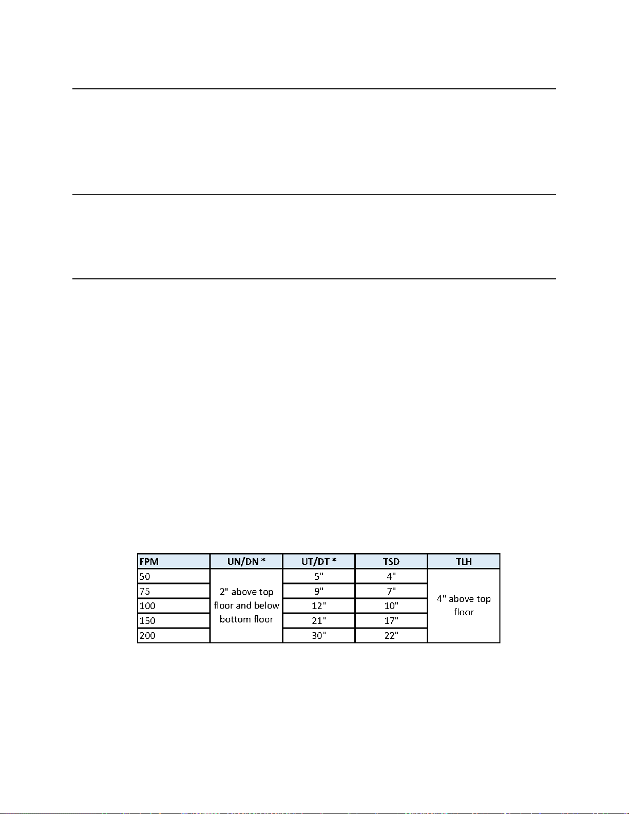
2.5 Normal and Top Terminal Slowdown Limits
The terminal slowdown limits include the Normal Terminal Slowdown Limits (including UN, UT, DN and
DT) and the Top Terminal Limits (including TSD and TLH). The Normal Terminal Slowdown Limits are
read from absolute positions on an encoded tape. The TSD and TLH limits are mechanical switches.
The Normal Terminal Limits are used to cause the car to slowdown and stop at or near the terminal
landing if the normal stopping means does not function properly. The NTS processor monitors the
position of the car in the hoistway from the APS selector camera and turns off the appropriate limit
switch, when the limit position is reached, independent of the Main CPU.
The Top Terminal Slowdown limits are used to prevent the car from hitting the stop ring on the hydraulic
jack at a speed greater 50 fpm. TSD and TLH limits must be mechanical switches installed on all
GALaxy eHydro controlled elevators and must be set to activate mechanically from the movement of the
car.
The distance that the limits are placed from the terminal landing depends on the speed of the car. Table
2-0 shows the slowdown limit locations with respect to contract speed. All distances are shown in
inches. The distances listed represent the distance from the terminal landing when the slowdown switch
is actuated.
Table 2-0: Slowdown Distances from Terminal Landings
Page 22

GALaxy eHydro Elevator Controller Section 2 –Installation
2-4
• * UT and DT limit distances are setup by parameters in the NTS Processor. UN and DN limits are
always 2” above and below the top and bottom terminal landings respectively.
The up and down directional limit switches UN and DN will be set to open two inches past the terminal
floor levels on the NTS processor and MAIN CPU. With the Absolute Position System (APS) selector
camera, the slowdown limit positions are automatically calculated by the NTS processor and Main CPU
boards. If the calculated slowdown values are not adequate, the distances for the NTS Processor and
the Main CPU can be modified from the Main CPU LCD Interface under the “NTS Proc Adj Vars” menu.
The Main CPU slowdown distances will always match the NTS processor distances.
2.6 Top Terminal Limit Switches
The Top Terminal Limit Hatch (TLH) switch should be set to open four inches above the top terminal
floor level. The Terminal Slowdown (TSD) switch should be set to open at the appropriate table value.
These two switches must be mechanical switches.
For the requirements for a running platform during initial start-up, refer to the GALaxy eHydro
Quickstart Guide or Section 3.2.1 of this manual.
2.7 Selector Installation
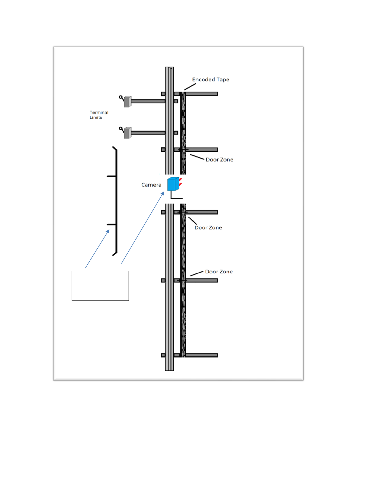
2.7.1 APS (Absolute Position System) Selector Installation
2.7.1.1 Installation of the Encoded Tape and APS Camera
Always handle the encoded tape with care to make sure that the encoded surface of
the tape is not damaged. Do not kink the tape or bend the tape in too tight of a
radius. When installing the tape, make sure that no grease, dirt, or debris is on the
encoded surface of the tape.
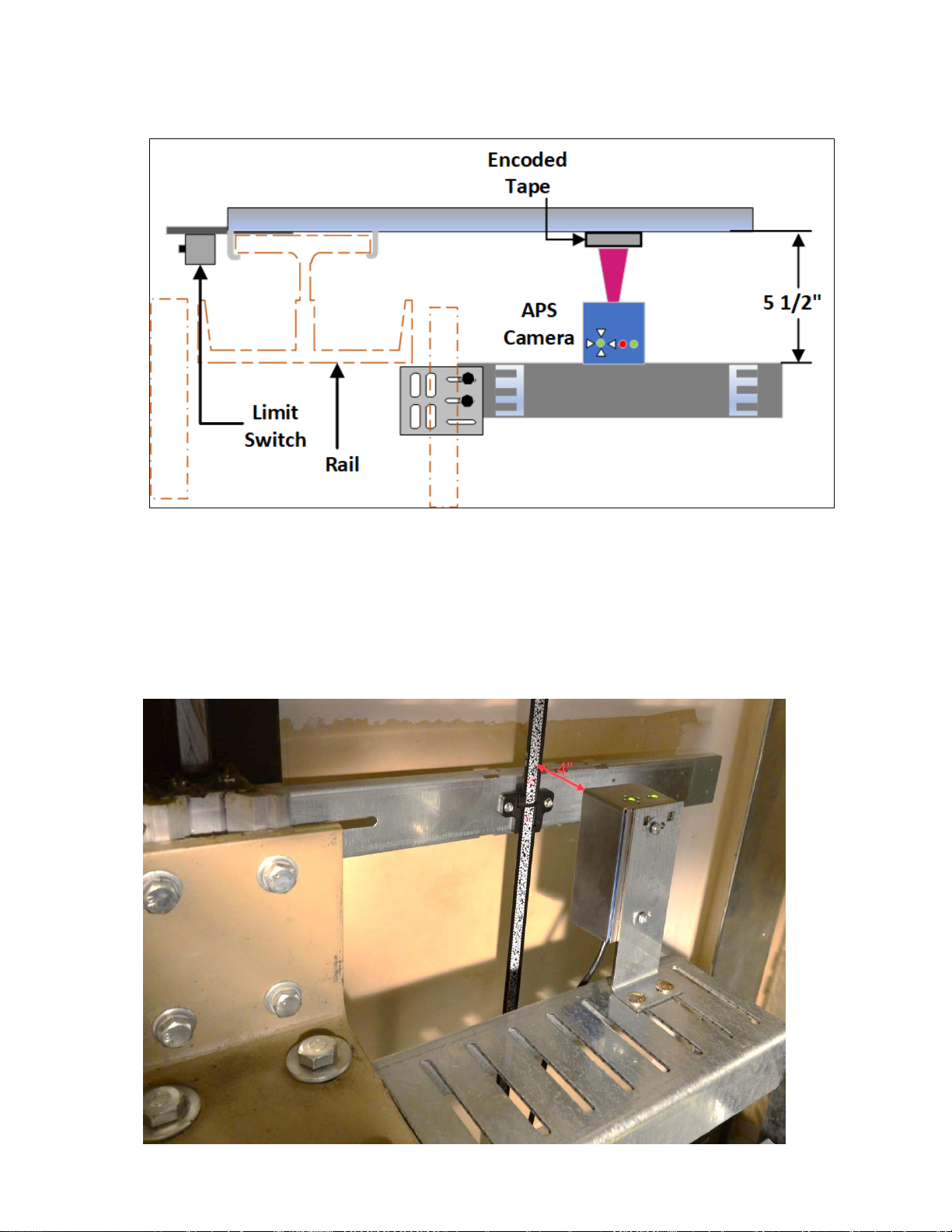
The general configuration of the APS (Absolute Position System) Selector is shown in Figure 2-0.
Page 23
GALaxy eHydro Elevator Controller Section 2 –Installation
2-5
Figure 2-0: APS Selector General Configuration
Camera and
Cam mounted
on the Elevator
Page 24

GALaxy eHydro Elevator Controller Section 2 –Installation
2-6
To install the APS Selector, follow steps 1 through 8 below:
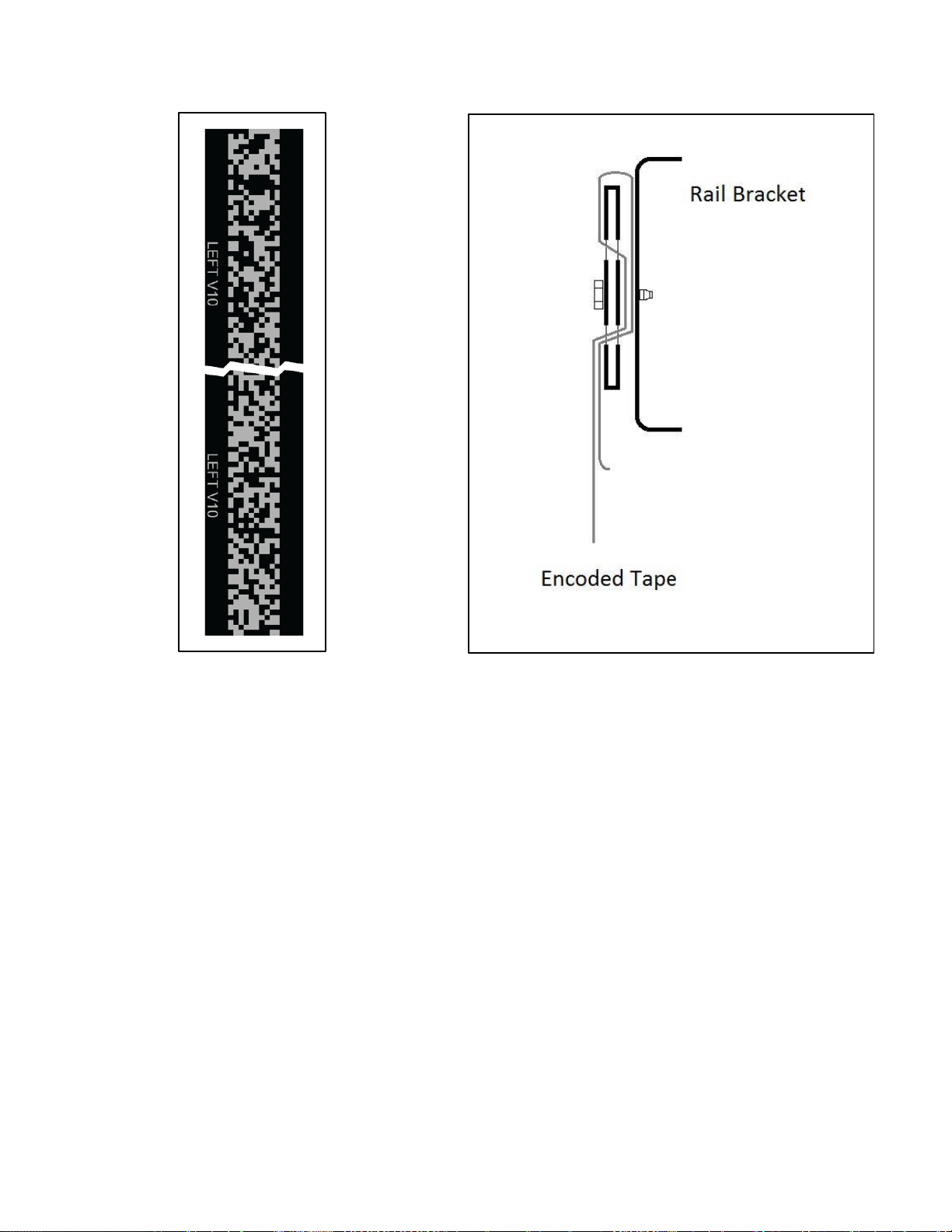
Step 1: Install top selector bracket and attach the encoded tape.
• Mount the top J-hook selector bracket to the rail.
• Make sure the bracket is high enough that, when the car is on the stop ring above the top
terminal landing, that the encoded tape is still within the field of view of the APS cameras, and
that nothing on the car contacts the bracket.
• Attach the encoded tape to the top bracket keeping the encoded tape as close to the rail as
possible. See Figure 2-1.
• Make sure to feed the tape through the front side of the bracket first (the side facing the car), and
then bend it around the top of the bracket and lace it back down. Make sure that the encoded
side of the tape faces the car and that the “LEFT” markings on the tape are on the left side. See
Figures 2-2 and 2-3.
• Fasten the tape with the supplied bracket and screws.
Figure 2-1: Encoded Tape Mounting – Top Bracket
Page 25
GALaxy eHydro Elevator Controller Section 2 –Installation
2-7
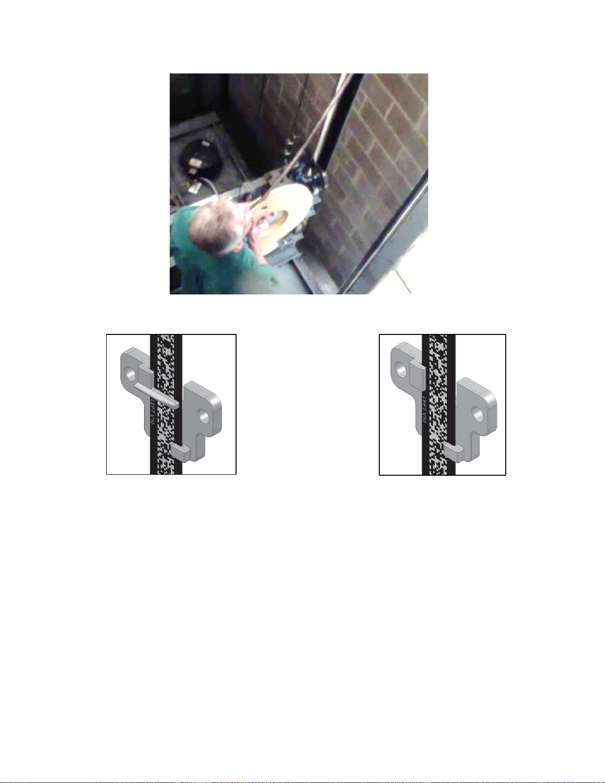
Step 2: Run down on inspection while unrolling the encoded tape.
• Run down on inspection while unrolling the tape. See Figure 2-4.
• Make sure you do not kink the tape or bend it in too tight of a radius. The tape can be
damaged, and it should be handled with care.
• Mount a J-hook selector bracket and guide clip with a door zone bridge for each floor. See
Figures 2-5 and 2-10.
• When the elevator is at floor level the door zone bridge should be positioned at the midpoint
between the two APS cameras. See Figure 2-14. The exact positioning of this bracket and guide
clip will be set in section 2.7.2.4.
• Where there are tall floor heights or blind hoistways, mount J-hook selector brackets and guide
clips without door zone bridges, at locations as needed, that will hold the encoder tape at the
proper position with respect to the guide rails and APS camera. See Figure 2-6.
• Make sure your hands are clean and you do not leave any grease or dirt on the front of the tape.
Figure 2-2: Front View of Encoded Tape
Figure 2-3: Side View of Top Bracket
Page 26
GALaxy eHydro Elevator Controller Section 2 –Installation
2-8
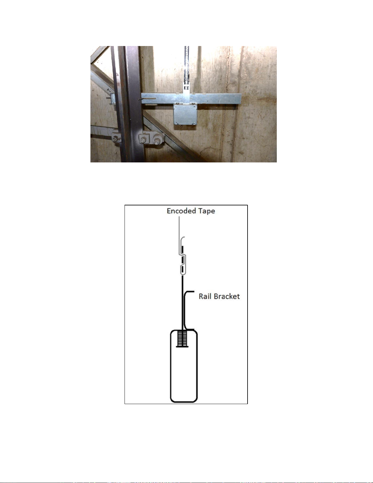
Step 3: Install the bottom selector bracket and attach the encoded tape.
• Mount the bottom selector bracket onto the car guide rail as shown in Figure 2-7.
• Make sure the bracket is low enough that, when the car fully compresses car buffer, that the
encoded tape is still within the field of view of the APS cameras, and that nothing on the car
contacts the bracket.
• Attach the encoded tape to the rail bracket with the slack tape switch.
• Make sure to feed the tape through the front side of the bracket (the side facing the car) first, and
then bend it back up toward the back of the tape. See Figure 2-8.
• Push the bracket down until the springs are depressed to the mark in order to properly tension
the encoded tape. See Figure 2-9.
• The slack tape switch should be properly installed and wired according to the wiring schematics
and connection diagrams
Figure 2-4: Unroll the Encoded Tape
Figure 2-5: Guide Clip with
Door Zone Bridge
Figure 2-6: Guide Clip without
Door Zone Bridge
Page 27
GALaxy eHydro Elevator Controller Section 2 –Installation
2-9
Figure 2-8: Side View of Encoded Tape Attachment to the Bottom Bracket
Figure 2-7: Lower Bracket Mounting
Page 28
GALaxy eHydro Elevator Controller Section 2 –Installation
2-10
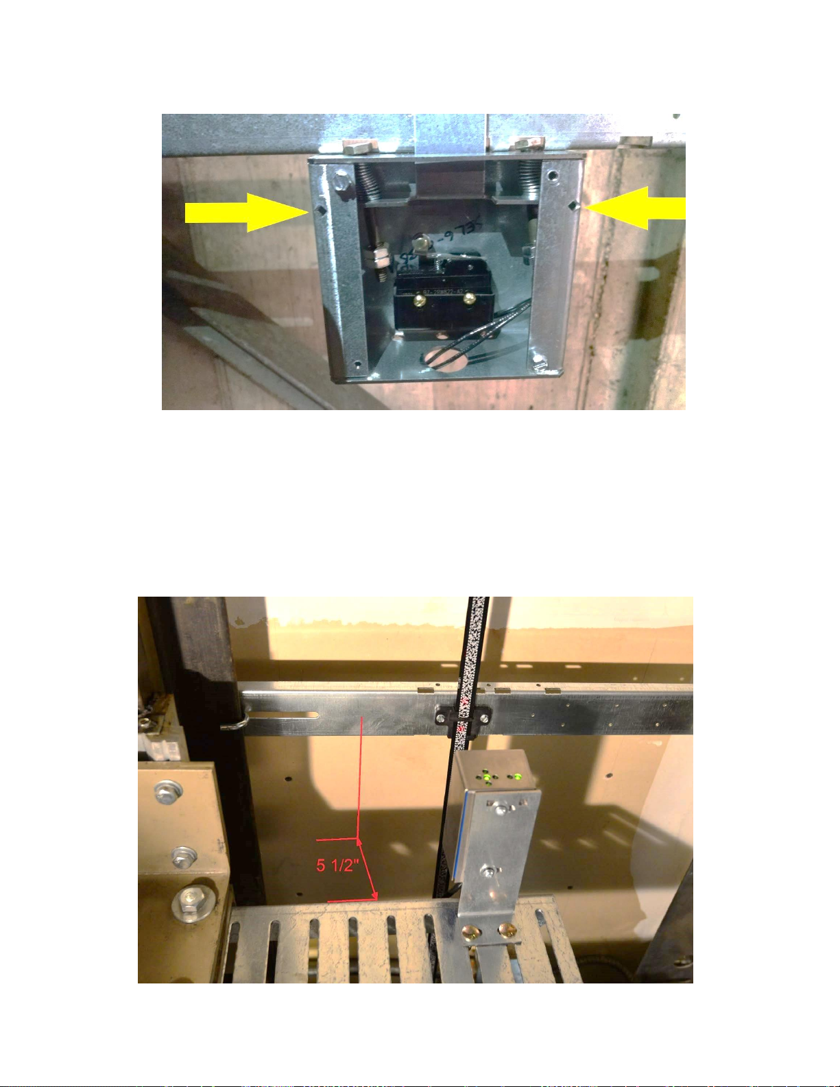
Step 4: Install the selector mounting bracket.
• Mount the selector mounting bracket to the cross head.
• Use the roller or slide shoe guide bolts to hold the camera bracket. The face of the bracket
should be about 5 ½ inches from the back of the rail. See Figures 2-10 and 2-11.
• The back of the bracket should be as close as possible to the crosshead channel.
• Use a level and make sure it is plumb and level.
Figure 2-9: Lower Bracket with Springs Properly Compressed to the Marks
Figure 2-10: APS Camera and Mounting Bracket
Page 29
GALaxy eHydro Elevator Controller Section 2 –Installation
2-11
Step 5: Install the APS Camera.
• Mount the camera on the mounting bracket.
• The APS camera should be centered with the encoded tape.
• The face of the camera should be 4 inches from the face of the tape. See Figure 2-12.
Figure 2-11: Top View of APS Camera and Mounting Bracket
Figure 2-12: APS Camera Mounted 4 Inches From Encoded Tape
Page 30
GALaxy eHydro Elevator Controller Section 2 –Installation
2-12
Step 6: Wire the APS Selector Camera according to the connection diagrams.
• The APS selector should be wired according to the job specific wiring schematic and
connection diagrams. See Figure 2-11.
Prior to performing “Step 7” below, the eHydro controller must be installed, and the APS selector
must be properly wired according to the wiring schematics. See Section 3 of this manual.
Step 7: Perform a fine adjustment of the APS camera.
• Make the fine adjustment of the camera using the LED array on the top of the APS camera. See
Figure 2-14.
• Adjust the camera so only the green LED in the middle of the 4 red arrows is on. See Figure
2-16.
• Temporarily obstruct the field of view of the APS camera for 5 seconds, and then remove the
obstruction. Two red alignment spotlights should appear on the encoded tape. These spotlights
represent the center of the field of view of each APS camera. Adjust the camera so the
spotlights are in the center of the encoded tape. See Figure 2-15.
• Level the APS camera with a leveling device. The APS camera must be parallel and square to
the encoded tape. See Figure 2-17.
• The PWR and STAT LED’s indicate the status of the APS. See Table 2-1.
Figure 2-13: Wire APS Camera According to Wiring Schematic and Connection Diagram
Page 31

GALaxy eHydro Elevator Controller Section 2 –Installation
2-13
LED
Color
Function
OFF
ON
Slow Blinking (1 Hz)
Fast Blinking (5 Hz)
PWR
Green
Supply voltage
No power
Power OK
--
--
STAT
Red
Status signal
No errors
Reading error
APS internal fault
Communication error
Figure 2-14: LED Array on
APS Camera
Figure 2-15: APS Camera Alignment
Spotlights
Figure 2-16: Fine Adjustment of the Camera Sensor
Table 2-1: APS Camera, PWR and STAT LED’s
Page 32

GALaxy eHydro Elevator Controller Section 2 –Installation
2-14
2.7.2 APS Selector Floor Position Setup (Hoistway Learn)
The hoistway learn procedure requires that the selector camera communicates properly with the Main
CPU and the NTS processor. The hoistway learn procedure also requires that the APS camera module
communicates properly with both CPUs on the selector interface board and with the main CPU in the
controller.
Proceed to Section 3 of this manual, and, once the “Prepare the Car for Hoistway Learn” section
is reached in section 3.3.3, return to section 2.7.2.1.
2.7.2.1 Verify that the APS Selector Camera is Installed Correctly and Communicating.
From the Diagnostic menu on the LCD Interface, select the Sel CAN Com Status. Verify that the CPU
to Selector Rx Error Cnt is zero, that the Rx Data Cnt is counting and that the On-line status equals 1.
Verify that the CNT A is not zero, that there are no Errors or Warnings and that the alignment is
centered and contrast shows OK. Also verify that the NTS to Selector status shows that the Rx Error
Cnt is zero, that the Rx Data Cnt is counting and that the On-line status equals 1. Continue to verify
that the CNT B value for NTS Processor is not zero, that there are no Errors or Warnings and that the
alignment is centered and contrast shows OK.
Figure 2-17: APS Camera Orientation
Page 33

GALaxy eHydro Elevator Controller Section 2 –Installation
2-15
2.7.2.2 Set the Adjustable Variables – “NTS Proc Adj Vars” in the Controller.
The following parameters must be setup prior to learning any floor positions.
• Set “Top Speed” to the contract speed of the job.
• Set “Num Valid Fl” to the number of floors with openings on this elevator.
• Set “UT Limit Dist” and “DT Limit Dist”. If set to zero, the distance is set automatically from the
slowdown table in the manual. If the parameter is changed, it will not take effect until a learn
operation is done at the top and bottom floor. It is recommended to set both parameters to zero
unless the slowdown distance need to be adjusted.
• Set “Can Baud Rate” to 0. 0 is 115.2K Baud. This parameter should not need to be changed.
2.7.2.3 Zero the Hoistway
After the NTS Processor parameters are setup, navigate to the Elevator Setup menu and select Learn
Hoistway. The diagram below, Figure 2-18, shows the initial part of Learn Hoistway process if done
from the machine room. To setup the hoistway from the car, you will only have to enter this menu the
first time to zero the hoistway table. Note that the number of valid floors and top speed will be verified
during this process. Be sure to select YES for First Time Setup and press ENTER. When you see the
message, “Setup Active. Hit Up or Dn to Scroll thru”, press MODE to escape to the main menu. You
are now ready to setup the floors from the car.
Figure 2-18: Learn Hoistway From Car
Page 34

GALaxy eHydro Elevator Controller Section 2 –Installation
2-16
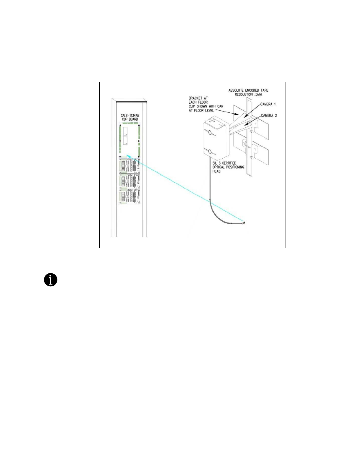
2.7.2.4 Setting Hoistway Floor Levels with APS Selector
• Put the elevator on car top inspection.
Temporarily set the car door bypass switch to the BYPASS position. Setting the car door
bypass switch to the BYPASS position will allow the car to be moved on car top
inspection with the car door open. All safety precautions must be followed to ensure the
safety of elevator personnel and the general public when moving the car on car top
inspection with the car door bypass switch in the BYPASS position.
• Move the jumper on the GALX-1134AN COP board to the setup position. See Figure 2-19.
Run/Setup
Jumper
Figure 2-19: GALX-1134AN COP Interface Board Setup Jumper
Page 35

GALaxy eHydro Elevator Controller Section 2 –Installation
2-17
• Move the car on inspection so that it is exactly level with a floor.
Pressing the door open button, while moving the car on inspection, will change the
inspection speed to 3 fpm during the inspection run. This allows the car to be positioned
at exactly floor level. The inspection speed will return to the value set for “Inspect Speed”
in the “Car Motion” Sub Menu when the door open button is not pressed.
• Adjust the J-hook bracket and guide clip so the door zone bridge is positioned at the
midpoint between the two APS cameras. If the alignment spotlights are not visible,
temporarily obstruct the field of view of the APS camera for 5 seconds, and then remove
the obstruction. Two red alignment spotlights should appear on the encoded tape. See
Figures 2-15 and 2-20.
Figure 2-20: APS Selector Alignment Spotlights
Page 36

GALaxy eHydro Elevator Controller Section 2 –Installation
2-18
• To record the floor position, press the buttons on the car operating panel in the following
sequence.
o Press the 2nd floor car call button
o Press the 1st floor car call button
o Press the 2nd floor car call button
o Press the 1st floor car call button
o Press the Door close button
The car call light for floors 1 and 2 will illuminate momentarily and then turn off.
After the two car call lights turn off, press the following button on the car operating panel.
o Press the car call button for the floor where the car is currently located.
This car call light will flash on and off for approximately 5 seconds and then remain off.
This indicates that the floor position was recorded successfully. If the car call light does
not flash, but remains illuminated, the floor was not recorded successfully. If the floor
position was not recorded successfully, verify that the APS SEL adjustable variables are
set properly.
The 1st floor car call is the car call for the bottom terminal landing. The 2nd floor car call is
the car call for the landing that is one floor above bottom terminal landing. The actual
floor markings for these floors may not be “1” and “2”.
• Repeat this process until all valid floors have been recorded.
Set the car door bypass switch to the OFF position.
• The hoistway learn is now complete.
• Proceed to section 3.3.3.
Page 37

GALaxy eHydro Elevator Controller Section 3 – GALaxy Startup and Adjustment
3-1
Section 3 - GALaxy Startup and Adjustment
3.1 Procedure for Initial Power-up of Controller
3.1.1 Checking Main Line Voltage
Prior to powering up the controller or attempting to run the hydraulic pump motor, the following steps
should be completed:
• Familiarize yourself with the wiring schematics.
All safety precautions, including precautions related to electrical safety, must be followed
to ensure the safety of elevator personnel and the general public.
• Before applying power to the controller, the following items should be verified by the
proper electrical authority.
o Verify that the disconnecting means is properly sized and is lockable.
o Verify that the voltage supplying the elevator controller is correct as indicated
on the “Controller Input” of the controller data tag.
o Verify that the conductors supplying the disconnecting means are properly
sized.
o Verify that the conductors from the disconnecting means to the controller are
properly sized.
o Verify that power supply feeding the controller has the proper fuse protection
or circuit breaker protection.
Verify that the power supply feeding the controller is properly grounded and that the grounding
conductor is properly sized.
3.1.2 Check Controller Voltage
Turn the main line disconnect to the on position. Check the voltage at R, S, and T on the Soft-Starter.
Verify that all three phases are present. Check the voltage at fuses L1 and L2 on controller. If correct,
check that the voltage at terminals “S10” and “L120” with respect to “GND” reads 120 VAC. Check that
the voltage across terminals “C24V” to “C24C”and “L24V” to “L24C” each reads 24 VDC. If any of these
voltages are not correct, check wiring diagram to determine problem before continuing. Verify what the
voltage for “FEP” and “HCP” match the voltage specified on the schematic.
3.1.3 Verify the Main CPU is Operating
Check to make sure that the “axy” of GALaxy on the Main CPU LCD interface is blinking. If the “axy” is
blinking, continue to the next step. If not, check voltage at terminals 5V to 0V on the 1121 Main I/O
board to insure 5VDC. If 5VDC is present and the “axy” on the Main CPU LCD interface is not blinking,
then contact factory.
Page 38

GALaxy eHydro Elevator Controller Section 3 – GALaxy Startup and Adjustment
3-2
3.2 Start-Up Procedures
3.2.1 Requirements for a running platform during initial startup
1) Wire Hydraulic Pumping Unit and Main Line Power as shown in the job connection diagrams.
2) If elevator requires a Governor, install and wire the Governor as shown in the job connection
diagrams.
3) Add temporary connections on the GALX-1121 Main I/O Board and on the I/O expansion boards
as shown in Figures 1, 2, and 3.
4) Set the toggle switches on the Main I/O Board as shown in Figure 3.
5) Place CN18 on pins 2 and 3, in the temporary “Test Mode” configuration, on the GALX-1121 Main
I/O Board, as shown in Figure 3.
All temporary connections must be removed before placing the elevator in service.
Figure 3-0: Typical I/O Expansion Board
Fire I/O Board
Figure 3-1: GALX-1121 Main I/O Board With
Run Bug. See Figure 3-2 For
Run Bug Stop Switch.
Page 39

GALaxy eHydro Elevator Controller Section 3 – GALaxy Startup and Adjustment
3-3
Figure 3-2: GALX-1121 Main I/O Board
See
Figure 3-1
For Run Bug
Connections
Page 40

GALaxy eHydro Elevator Controller Section 3 – GALaxy Startup and Adjustment
3-4
6) Check/set parameters in the controller LCD user interface. See “eHydro Controller Settings” in
Table 3-0.
Preset the following parameters from the LCD User Interface “Adjustable Variables” menu.
Adjustable Variables - Car Motion
Adjustable Variables - System Options
APS Dead Zone = 0.25 inches
Hall Lan Baud = 3 (19,200)
Stop On PosCnt = 0 (To be set in final setup)
Adjustable Variables - NTS Processor
High Spd Ins = 0 (0=slow speed inspection)
Top Speed = Contract Speed
Number Valid Fl = Number of Valid Floors
UT Limit Dist = 0
DT Limit Dist = 0
7) Preset the hydraulic valve according to the manufacturer’s instructions.
8) Verify that the hydraulic pumping unit motor rotates in the correct direction.
9) If the motor rotation is not correct, disconnect power and swap the motor starter wires connected
to the “Softstarter” terminals 1-L1 and 3-L2. After swapping these wires, re-apply power and
verify that the motor rotates in the correct direction.
10) If the Sprecher Schuh Softstarter generates a “Phase Reversal” fault, verify that dip switch 9 on
the Softstarter is set properly. See the Sprecher Schuh Softstarter manual for instructions on the
proper setting for dip switch 9.
• Verify that the elevator is safe to operate as a running platform and that all individuals are
clear of moving machinery.
• Make sure all hoistway and car doors are closed.
11) Adjust the speed of the platform in the up and down directions according to the hydraulic valve
manufacturer’s instructions.
3.2.2 Complete the Installation of Equipment
Before beginning the adjustment process, the installation of all equipment should be complete including
the following items. See Section 2 for the installation procedures.
• All field wiring, safety circuits, and safety devices should be installed.
• The APS selector system should be installed including the “door zone bridge” guide clips.
• All Terminal Limit switches should be installed.
• All car doors and car door electric contacts or car door interlocks should be installed.
• All hoist doors and hoistway door interlocks should be installed.
Table 3-0: eHydro Controller Settings
Page 41

GALaxy eHydro Elevator Controller Section 3 – GALaxy Startup and Adjustment
3-5
3.3 Adjustment Procedures
• Remove all temporary connections.
• Verify that all safety circuits and safety devices are installed and functioning properly.
• Verify that all car door electric contacts or car door interlocks are functioning properly.
• Verify that all hoistway door interlocks are functioning properly.
• Verify that all hoistway doors and car doors are closed.
• Verify that the elevator is safe to operate and that all individuals are clear from moving
equipment.
3.3.1 Set Toggle Switches
Set all toggle switches on the 1121 Main I/O board as follows:
• DOOR LOCKS - "OFF"
• IND - "IND"
• AUTO DOOR - "OFF"
• STOP - "RUN"
3.3.2 Ready the Car to Run on Inspection
The car should be ready to run on inspection if all is wired correctly. Select the “Elevator Status” on the
Main CPU LCD interface. The display should show INS on the car service area of the first main display.
Pressing the DOWN button to the next display will show the type of inspection the car is on as in the list
below:
• Machine Room
• Car Top
• Access
• In-Car
• Car Top Lock Bypass
• Car Top Gate Bypass
• Car Top G & L Bypass
• COB HW Setup Jumper
To run the car from the machine room, Machine Room inspection should be displayed.
The “inspection string” consists of contacts from the inspection switches and the gate and lock bypass
switches in series as shown in Figure 3-3. One and only one of the five inspection inputs should be on
for the car to run..
NOTE: Any one of the following conditions will generate an inspection error.
• More than one inspection input is on
• No inspection input is on
• Gate or Lock Bypass switch in the BYPASS position when the car is not on car top inspection
Page 42

GALaxy eHydro Elevator Controller Section 3 – GALaxy Startup and Adjustment
3-6
Figure 3-3: Inspection String Circuit
3.3.3 Prepare for the Car for Hoistway Learn
Return to section 2.7.2.1, “Veirfy that the APS Selector Camera is installed Correctly and
Communicating”. Complete sections 2.7.2.1 through 2.7.2.4. After completing section 2.7.2.4,
return to this section, 3.3.3, and complete the following items.
Page 43

GALaxy eHydro Elevator Controller Section 3 – GALaxy Startup and Adjustment
3-7
• Place the RUN/SETUP jumper on the GALX-1134AN COP Interface Board to the RUN position.
• Place the CN18 jumper on the GALX-1121An MAIN I/O board to No Test Mode 1 – 2.
• Check that all the floor positions have been learned by selecting “Hoistway Tables”->” Dpy APS
Sel Valid Floors”. The display should show a bit set for each valid floor.
Even though the car may start at floor 2 or 3 and even skip floors, the selector always starts
from one and increments the floors consecutively to show only valid floors. If there are 5 valid
floors, 5 bits must be set.
• If a bit is zero, then run the car on inspection to that floor, make sure the car is dead level and
learn the floor from the procedure in sections 2.7.2.1 through 2.7.2.4., or from the LCD
Interface, “Elevator Setup”->” Learn Hoistway”. Follow the prompt from the LCD display and
make sure not to mistakenly clear the hoistway table if floors have already been learned.
Select to NO when prompted to “Clear HW Table<U/D>? No”.
3.3.4 Verify the Hoistway
With all the floors learned, run the car on inspection from bottom to top and verify that door zone signals
(UL, DL and DZ) and the NTS limit output modules (UN, DN, UT and DT) all work as expected.
The NTS top and bottom limits are set automatically from a table when the top or bottom floor
is learned respectively.
To manually change the NTS limits, perform the following items.
• Change the “UT Limit Dist” or “DT Limit Dist” value from the “Adjustable Variables”->” NTS Proc
Adj Vars”->” menu. The value is set in inches from the terminal floor.
• Run the car to the top or bottom floor, learn the floor and then run to the opposite floor and
again learn the floor. The new distances will be used at each terminal landing.
The selector will use the internal table value if limit distance parameter that is set to zero.
3.4 Adjust the Elevator
3.4.1 Automatic Run
• Turn the "AUTO DOOR" switch to the "OFF" position and the "IND" switch to the "IND" position.
• Take the car off of inspection operation to allow it to relevel to a floor. If the learn procedure
was successful, the elevator should be ready to make an automatic run.
• From the Main CPU LCD interface, press the MODE button until the Elevator Status display is
shown. See Figure 3-4.
Pressing ENTER from any screen in the Elevator Status display will access the car call popup
window.
Page 44

GALaxy eHydro Elevator Controller Section 3 – GALaxy Startup and Adjustment
3-8
• Press ENTER, select a car call floor and press ENTER again. The elevator should run to
answer the call.
• When the elevator levels in and stops at the floor, the doors will remain closed. The speed of
the car can be monitored on this screen with each run as well as the pump motor “ ”, the
direction “ ”, the slow speed valve “ ” and the high-speed valve “f” (up fast or down fast).
• Press the UP or DOWN button until the Accel/Decel screen is displayed as shown in Figure 3-5.
Each time the car runs, the Accel/Decel screen will show the acceleration rate and deceleration rate in
the up or down direction. The deceleration rate is displayed as a negative number. In the example
above, the up direction run acceleration rate is 55 fpm/s and the deceleration rate is 58 fpm/s. The
down direction run accel and decel rates are 63 and -67, respectively. Also shown on the screen are
the up and down slowdown distances (USD, DSD) displayed as 20.0 inches each and the up and down
leveling distances (ULD, DLD) displayed as 10.8 and 0 inches. The ULD or DLD values are only valid
after the car levels into the floor in the respective direction.
The displayed values on each of the above status screens can be used to aid in adjusting the slow
speed and high-speed valves.
3.4.2 Adjust the Slowdown Distances
When the hoistway floor positions are initially set to zero, the slowdown values are also set to zero.
Then when the hoistway learn is complete, any slowdown values that are zero are set from an internal
slowdown table to give the mechanic a starting point.
To adjust the slowdown, run the car on automatic to each floor, and adjust the hydraulic valve to
provide a smooth deceleration and leveling speed into the floor.
After setting the deceleration rate on the hydraulic valve, the slowdown distances can be adjusted to
provide approximately 2 to 3 inches of stabilized leveling speed. Refer to the hydraulic valve
manufacturer’s adjustment procedure to properly adjust the hydraulic valve.
To adjust the individual floor slowdown distances can be adjusted by changing the individual floor up or
down slowdown count values by navigating to the "Hoistway Tables" menu and then "Floor & SD
Figure 3-4: Elevator Status Display
Figure 3-5: Accel/Decel Display
Page 45

GALaxy eHydro Elevator Controller Section 3 – GALaxy Startup and Adjustment
3-9
Count" display. See Figure 3-6. From this screen, Down Slowdown (DS) count, the floor count and Up
Slowdown (US) count can be set.
Press UP or DOWN to access the desired floor and then press ENTER to go into edit mode. Use the
UP and DOWN buttons to position the cursor “>” to the desired DS slowdown or US slowdown count,
and then press ENTER again to edit that count. After the value is changed, press ENTER to save the
value. Press MODE to exit out of this menu. The slowdown counts can be changed for any floor.
3.4.3 Adjust the Stop
When at floor level, the “UL, DL, & DZ” LEDs should be on. If the elevator continually tries to seek floor
level by leveling up and down, try the following steps to correct the problem:
• Reduce the leveling and re-leveling velocity by adjusting the leveling speed adjustment on the
valve.
• Increase the APS Dead Zone parameter in the Car Motion menu.
If the car stops hard, readjust the final stop on the valve. Again, refer to the adjustment procedure of the
valve manufacturer. Make sure the "Soft Stop Time" parameter is set to about 1.5 seconds.
The floor level positions are set by placing the car at the exact floor location and then selecting to learn
the floor position. When the floor position is learned, the count value is automatically placed in the
Hoistway Table as a count that is read from the tape.
The UL and DL locations are calculated to be 8 inches apart + or – the APS Dead Zone distance
parameter. No door zone magnet is used. An exact stop can be achieved with setting the car to stop
on pulse counts.
With "Stop On Pos Cnt = 1", adjustment for the Up or Down Level Distance is found in the “UL & DL
Distance” menu in “Hoistway Tables”. See Figure 3-7. The Pulses/Inch (PPI=50.8) is also display on
this screen. Be familiar with how much each pulse will affect the stop.
The variables “Dn Level” and “Up Level” are used as the number of pulse counts to continue moving
before issuing a stop sequence after the exact level position of the door zone is reached (UL and DL
both on). “Dn Level” is used when the car is running down and “Up Level” when the car is running up.
Changing the "Dn Level" and the "Up Level" variables will change the leveling distance at all floors.
Figure 3-6: Accel/Decel Display
Figure 3-7: UL & DL Distance Display
Page 46

GALaxy eHydro Elevator Controller Section 3 – GALaxy Startup and Adjustment
3-10
To make floor position count changes at individual floors select the "Hoistway Tables" menu and then
the "Floor & SD Count" screen. See Figure 3-8. Hit UP or DOWN to access the desired floor and then
press ENTER to go into edit mode. Change the floor count to the desired location and then run the car
away from the floor and then back again.
If the car stops in the desired level position, place the car on inspection and learn the floor from the
procedure in section 2.7.2. The floor position can also be relearned in the Machine Room from the LCD
Interface, “Elevator Setup”->” Learn Hoistway”. Follow the prompt from the LCD display and make sure
not to mistakenly clear the hoistway table if floors have already been learned, i.e., select NO when
prompted to “Clear HW Table<U/D>? No”. When the new value for the floor is learned, the floor count
value is also updated in the NTS Processor. This will make sure that the door zone positions for both
the Main CPU and the NTS Processor turn on at the same time.
3.4.4 Verify Proper Operation of All Safety Circuits and Signal Devices
• Remove all temporary connections.
• Verify that all safety circuits and safety devices are installed and functioning properly.
• Verify that all car door electric contacts or car door interlocks are functioning properly.
• Verify that all hoistway door interlocks are functioning properly.
• Verify that all signal devices are functioning properly.
3.4.5 Perform Required Tests
Complete all required inspections and tests before placing the elevator in service.
Figure 3-7: Floor and SD Count Display
Page 47

GALaxy eHydro Elevator Controller Section 4 - Troubleshooting
4-1
Section 4 Troubleshooting
4.1 General Information
The GALaxy controller is equipped with a number of features that aid in troubleshooting any problems
that may occur. The physical layout of the controller provides ready access to all I/O to make voltage
measurements. All I/O boards, except for the Main I/O board, have LED’s that monitor the state of the
input. The controller is equipped with an LCD interface on the Main CPU board that displays the I/O
status of Main I/O board, Safety PAL (FPGA) and the NTS Processor. The LCD Interface section
describes the use of the Main CPU LCD interface. In this section, the basic points of troubleshooting will
be detailed.
4.2 Microprocessor CPU
The CPU is very reliable and normally trouble free. With power turned on, the “axy” in GALaxy on the
Main CPU LCD interface should be blinking at one second intervals to indicate that the CPU is running.
If it is not blinking, then check voltage at the 5V terminal with respect to the 0V terminal on the Main I/O
board. This voltage should read 5VDC. If not, then check the input and output voltage of the DC power
supply. If the “axy” is not blinking and 5VDC is present at the 5V terminal with respect to the 0V
terminal, then contact the factory. All job parameters that are field adjustable are stored in a nonvolatile MRAM chip on the Main CPU board.
4.3 Input/Output Boards
The two main sections of all the I/O boards are the low voltage and the high voltage sections. The low
voltage section consists of all the digital interfacing necessary for the CPU to communicate with the field
components. The high voltage section consists of the field components (buttons, switches, lights, relays
and sensors) and their associated input and output signals. The standard voltage for the Main I/O board
and the COP board is 120VAC. However, the I/O expansion boards can accept a voltage range from 24
VAC, 24 VDC and 120 VAC. Serial Hall Call and Hall lantern board are only 24 VDC.
It is very important that the wiring schematics are reviewed in order to determine the voltages for which
the controller was designed before applying power. The majority of problems that may arise with the
control system are due to faulty inputs or outputs on the high voltage side of the system. For example,
having a limit switch not feeding voltage or an acknowledgment light turning on. The GALaxy control
system is designed to enable the technician to check both the high voltage section and the low voltage
section to correct the problem.
The high voltage section is checked with a digital voltmeter, or if available, with the individual LEDs that
are associated with the input. Depending on the particular input or output, the voltage measured at the
terminal will either be “high” or “low” with respect to its reference point. For example, to determine if the
car top inspection input switch was conducting, the voltage should be measured at terminal “INS” with
respect to “GND”. If the switch is feeding it should read 120VAC. If the switch is open, the voltage
should read less than 50VAC.
The previous example determines whether or not the field component is functioning properly. However,
to determine if the signal is actually being communicated to the CPU, the signal must be checked on the
low voltage section of the board. The low voltage section is checked from the Main CPU LCD interface.
Using the previous example, from the Main CPU LCD interface, navigate to the "Inputs and Outputs"
menu, "Car Inputs and Outputs" and scroll through the I/O list until the "INS" input is located. The LCD
will display "INS " if the inspection switch is feeding and "INS " if the switch is open.
Page 48

GALaxy eHydro Elevator Controller Section 4 - Troubleshooting
4-2
All of the I/O’s are optically isolated between the high voltage section and the low voltage section. The
inputs on the GALX-1121 Main I/O board and the GALX-1134 COP board are separated into 8 inputs
per board (GALX4-0048N input board) that mounts on the larger boards. If an input is determined to be
faulty, the GALX4-0048N board is replaced instead of the input opto-isolator chip. The outputs that are
plugged into the GALX-1121 Main I/O board are short circuit protected and can withstand a direct short
across the terminals. There are two outputs per output board and are covered with a red plastic
protective case. If an output on the MAIN I/O board is determined to be faulty, then the GALX4-0049N
output board is replaced.
The input opto-isolators and the output solid-state relays on the 1106 and 1107 I/O boards are socketed
IC's that are labeled on the silk screen of the various I/O boards with a "U" number (for example U45). If
it is determined through the previous troubleshooting procedures that the input signal is present at the
terminal, but is not being communicated to the CPU, the input opto-isolator may be defective and can
be replaced in the field. If it is determined that the CPU is communicating the output signal to the solidstate relay, but the voltage does not go high at the terminal, the solid-state relay may be defective and
can be replaced in the field.
The 1123 I/O board has current limiting inputs and short circuit protected outputs. If it is determined
that any I/O on the 1123 board is faulty, the board must be replaced.
Any time IC’s or I/O boards are replaced, the power should be turned off and care should be taken in
removal of the old chip or board and replacement of the new one. All of the I/O and their associated
IC’s or boards are listed in the wiring schematics.
4.4 Run Sequence
The following diagram in Figure 4-0 shows the run sequence of the controller for an up and down run.
Note that the RUN relay picks before SU or SD but drops at the same time as SU or SD.
Figure 4-0: RUN Sequence
Page 49

GALaxy eHydro Elevator Controller Section 4 - Troubleshooting
4-3
4.5 The Safety PAL Functions
The Safety PAL monitors the Main CPU RUN and Door Zone outputs, the NTS Terminal Limit and Door
Zone outputs, car Inspection and Door Gate/Lock inputs, and the speed outputs from both the Main
CPU and the NTS. The Safety PAL’s job is to interrupt or prevent a run operation in case of an unsafe
conditions.
Run Control - CPU Control outputs gated by Safety PAL:
SU – Solenoid Up Command
MC – Motor Contactor
SD – Solenoid Down Command
MC1 – Dual Motor Contactor
SUF – Solenoid Up Fast Command
STE – Soft-Starter Enable
SDF – Solenoid Down Fast Command
RUN – Run Relay Command
Door Zone Status – CPU Control and NTS MCU Control UL – Up Level
DL – Down Level
DZ – Door Zone
SEL_OK – Communications to Selector OK and no Selector Fault
SPD150 – Speed greater than 150 fpm
SPD75 – Speed greater than 75 fpm
Door Status:
DLT – Door Lock Top
GS – Car Gate Switch or Lock
DLM – Door Lock Middle
RLM – Rear Lock Middle
DLB – Door Lock Bottom
RGS – Rear Gate Switch or Lock
GBP – Gate Bypass
LBP – Lock Bypass
Inspection Status & Control:
GLB – Gate/Lock Bypass
AUTO– Automatic Operation
INS– Car Top Inspection
ICI – In Car Inspection
IU – Car Top Inspection Up
ACC – Access
ID – Car Top Inspection Down
TAU – Top Access Up
MRIN – Motor Room Inspection
TAD – Top Access Down
MRIU – Motor Room Inspection
UP
BAU – Bottom Access Up
BAD – Bottom Access Down
MRID – Motor Room Inspection
Down
Terminal Limit Status – NTS MCU Control outputs gated by Safety PAL:
UN – Up Normal Limit
UT – Up Terminal Slowdown
DN – Down Normal Limit
DT – Down Terminal Slowdown
Figure 4-1 illustrates all the Main CPU, NTS Processor and Safety PAL functions:
Page 50

GALaxy eHydro Elevator Controller Section 4 - Troubleshooting
4-4
Figure 4-1: Main CPU, NTS and Safety PAL System
Page 51

GALaxy eHydro Elevator Controller Section 4 - Troubleshooting
4-5
Figure 4-2: GALX-1121 Main I/O Board
4.6 Safety PAL
The Safety PAL has a fault LED located in the middle left of the board that indicates there is a PAL
fault. See Figure 4-2.
Important: When the LED is on, the car is prevented from running.
The Safety PAL performs the following functions:
• Verifies that the Up or Down Fast solenoid turns off when the terminal limits are activated
• Verifies that the doors are closed and safe to run
• Verifies all inspection operations
• Verifies that the car velocity is not greater than 150 fpm in the door zone and with the doors
open or running on inspection.
While the Safety PAL cannot turn on any run control signals, it can turn off the follow signals from the
Main CPU: RUN, SU, SUF, SD, SDF, MC, MC1, STE and from the NTS Processor: UN, UT, DN, and
DT.
When troubleshooting errors detected by the Safety PAL, take the following steps:
Check LED status of the PAL FAULT.
• Check the NTS CPU and NTS COM are blinking at one second intervals. Check that the NTS
CPU FAULT LED is off.
• From the Main CPU LCD interface, navigate to the "NTS Inputs and Outputs" menu, and view
all of the I/O status of the NTS CPU. Navigate to the “PAL Inputs and Outputs” menu and view
all of the I/O status of the Safety PAL.
• From the Main CPU LCD interface, navigate to the "Fault Log" menu, and view the recorded
faults for any fault related to the NTS processor or I/O’s that are input to the Safety PAL.
Page 52

GALaxy eHydro Elevator Controller Section 4 - Troubleshooting
4-6
4.7 System Faults
Faults that are detected by the Main CPU can be viewed on the Main CPU LCD interface by navigating
to the "Fault Log" menu, "View Fault Log". The lists of possible faults detected by the Main CPU are
listed in section 6, Main CPU Faults. By pressing the "ENTER" button on the Main CPU LCD interface
when the particular fault is being displayed, the interface will display detailed information for that fault in
the same format as the Elevator Status Screens.
In general, when a fault occurs, the system records the state of 168 bytes of data and stores the data in
two different buffers, the normal and long-term fault buffers. The normal fault buffers can hold the last
50 faults that occurred, and the long-term fault buffer holds the last 350 faults that occurred. The data
in the normal fault buffer is accessed from the “Fault Log” menu. The long-term fault buffer can be
copied to the SD Card and viewed from a PC using a text editor such as Word Pad.
4.8 Main CPU Inputs and outputs
Table 4-1: Main CPU Inputs & Outputs
Name
Description
1CA-nCA
1st – Nth Floor Car Call Acknowledge Outputs
1CAR-nCAR
1st – Nth Floor Rear Car Call Acknowledge Outputs
1C-nC
1st – Nth Floor Car Call Inputs
1CR-nCR
1st – Nth Floor Rear Car Call Inputs
1U-(n-1) U
1st – (Nth-1) Floor Up Hall Call Inputs
1UA-(n-1) UA
1st – (Nth-1) Floor Up Hall Call Acknowledge Outputs
1UAR-(n-1) UAR
1st – (Nth-1) Floor Rear Up Hall Call Acknowledge Outputs
1UR-(n-1) UR
1st – (Nth-1) Floor Rear Up Hall Call Inputs
2DA-nDA
2nd – Nth Floor Down Hall Call Acknowledge Outputs
2DAR-nDAR
2nd – Nth Floor Rear Down Hall Call Acknowledge Outputs
2D-nD
2nd – Nth Floor Down Hall Call Inputs
2DR-nDR
2nd – Nth Floor Rear Down Hall Call Inputs
ACC
Access Operation Input
AD
Automatic Door Switch Input
ALM
COP Alarm Input
ALMR
Rear COP Alarm Input
ALT
Alternate Fire Smoke Detector Sensor Input
ATT
Attendant Operation Input
ATTDN
Attendant Down Input
ATTUP
Attendant Up Input
AUTO
Automatic Operation Input
BAD
Bottom Access Down Input
BAU
Bottom Access Up Input
BF
Bottom Final Input
BP
Fire Phase I Smoke Detector Bypass Input
BUZ
Machine Room Buzzer Output
Page 53

GALaxy eHydro Elevator Controller Section 4 - Troubleshooting
4-7
Table 4-1: Main CPU Inputs & Outputs
Name
Description
CDL
Cab Down Lantern Output
COL
Counter Weight Collision Switch Input (Traction Elevators)
CS
In Car Stop Switch Input
CSPI1-3
Car Spare Input 1 – 3
CSPO1-3
Car Spare Output 1 – 3
CSS
Car Safety String Input
CST
Car Stop Switch Input
CTA
Car Top Automatic Input
INS
Car Top Inspection Input
CTS
Car Top Stop Switch Input
CUL
Cab Up Lantern Output
DC
Door Close Output
DCB
Door Close Button Input
DCBR
Door Close Button Rear Input
DCC
DAC Clear Output
DCL
Door Close Limit Input
DCLR
Door Close Limit Rear Input
DCR
Door Close Rear Output
DDA
Down Direction Arrow Output
DET
Detector Edge Input
DETR
Rear Detector Edge Input
DL or DLc
Down Level Position from Main CPU position reference
DLB
Door Lock Bottom Input.
DLB-1
Door Lock Bottom Secondary Input
DLM
Door Lock Middle Input
DLM-1
Door Lock Middle Secondary Input
DLO or DLcO
Down Level Output LED from Main CPU
DLT
Door Lock Top Input
DLT-1
Door Lock Top Secondary Input
DN
Down Normal Limit NTS Processor Output
DNi
Down Normal Limit Input from NTS Processor Output
DN-1 or DNc
Down Normal Output from Main CPU position reference
DO
Door Open Output
DOB
Door Open Button Input
DOBR
Door Open Button Rear Input
DOL
Door Open Limit Input
DOLR
Door Open Limit Rear Input
DOR
Door Open Rear Output
DPM
Door Protect Monitor Input
DT
Down Terminal Limit NTS Processor Output
DTi
Down Terminal Limit Input from NTS Processor Output
Page 54

GALaxy eHydro Elevator Controller Section 4 - Troubleshooting
4-8
Table 4-1: Main CPU Inputs & Outputs
Name
Description
DT-1 or DTc
Down Terminal Slowdown Output from Main CPU position reference
DZ
Door Zone Input from Safety PAL (And of NTS and Main CPU)
DZ-1 or DZc
Door Zone Output from Main CPU position reference
DZA or DZAc
Door Zone Output from Main CPU position reference
DZO or DZcO
Door Zone Output LED from Main CPU
ED
Extended Door Time Input
EE
Electric Eye Input
EER
Electric Eye Rear Input
EMP
Emergency Power Input
EPS
Emergency Power Select Input
EPT
Emergency Power Transfer Input
EQ
Earthquake Sensor Input
EXT
Car Top Exit Switch Input
FAN
Cab Fan Output
FB
Fire Buzzer Output
FBNB
Fire Buzzer/Nudging Buzzer Output
FF
Full Field Pilot Output
FFS
Fire Fighters Stop Switch Input
FL
Fire Phase I Light Output
FS
Fire Phase I On Hall Switch Input
FS2
Fire Switch Phase II On Input
FS2C
Fire Switch Phase II Call Cancel Input
FS2H
Fire Switch Phase II Hold Input
FST
Fire Stop Switch Override Output
FSTi
Fire Stop Switch Override Input
FSTP
Fire Stop Switch Override Output
GBP
Gate Switch Bypass Input.
GLB
Gate or Lock Bypass Open
GOV
Governor Switch Input
GS
Car Gate Switch Input
GS-1
Gate Switch Secondary Input.
GSPI1-3
Group Spare Input 1 – 3
GSPO1-3
Group Spare Output 1 – 3
GTS
Rope Gripper Trip Switch Input.
HB
Handicap Buzzer Output
HBE
Handicap Buzzer Enable Input
HSS
Hatch Safety String Input
HWLRN
Hoistway Learn
HWS
Hoistway Smoke Sensor Input
HWS2
Hoistway Smoke Sensor 2 Input
HWSET
COP Hoistway Setup Mode Jumper Input
Page 55

GALaxy eHydro Elevator Controller Section 4 - Troubleshooting
4-9
Table 4-1: Main CPU Inputs & Outputs
Name
Description
ICI
In-Car Inspection Input.
ICR
Inconspicuous Riser Input
ID
Car top Inspection Down Input
IEN
Car Top Inspection Enable
IFB
Inspection Fire Buzzer Output
IFL
Inspection Fire Light Output
IND
Independent Input
INDC
Independent Input in COP
ISER
In Service Output
ISPD
Inspection Speed Output
IU
Car Top Inspection Down Input
L120
Lantern 120 VAC
L120B
Lantern 120 VAC Secondary Input
LBP
Lock Bypass Input
LD
Down Hall Lantern Output
LDR
Rear Down Hall Lantern Output
LIG
Cab Light Output
LOS
Low Oil Switch Input
LPS
Low Pressure Switch Input
LU
Up Hall Lantern Output
LUR
Rear Up Hall Lantern Output
LWA
Load Weighing Anti-nuisance
LWB
Load Weighing Bypass Input
LWD
Load Weighing Dispatch
MC
Motor Contactor Output
MC1
Dual Motor Contactor Output
MC1i
Dual Motor Contactor Input.
MCi
Motor Contactor Input.
MES
Main Egress Smoke Detector Sensor Input
MRID
Motor Room Inspection Down Input.
MRIE
Motor Room Inspection Enable Input
MRIN
Motor Room Inspection Input.
MRIU
Motor Room Inspection Up Input.
MRS
Motor Room Smoke Sensor Input
MRSW
Motor Room Stop Switch
MSPI1-3
Machine Room Spare Input 1 – 3
MSPO1-3
Machine Room Spare Output 1 – 3
MTO
Motor Overload
NBFB
Nudging/Fire Buzzer Output
NTSCM
NTS Com COP LED Output
NTSF
NTS Processor Fault
Page 56

GALaxy eHydro Elevator Controller Section 4 - Troubleshooting
4-10
Table 4-1: Main CPU Inputs & Outputs
Name
Description
NUD
Door Nudging Output
NUDR
Door Nudging Rear Output
OVL
Overload Input
P1-Pn
1ST – Nth Discrete Floor Position Indicator Outputs
PALF
Safety PAL Fault
PS
Pit Switch Input
RDOOR
Rear Door Jumper
RGS
Rear Car Gate Switch Input.
RGS-1
Rear Car Gate Switch Secondary Input
RLM
Rear Lock Middle Input.
RLM-1
Rear Lock Middle Secondary Input
RPM
Rear Door Protection Monitor
RST
Reset Drive Output
RTL
Return to lobby Input
RUN
Run Output Relay Control
RUNi
Run Input
S10
Run Control 120 VAC
S10
Controller Power Input
SD
Solenoid Down Run Output
SDF
Solenoid Down Fast Output
SDFi
Solenoid Down Fast Input
SDi
Solenoid Down Run Input
SE
Safety Edge Input
SELCM
Selector Com COP LED Output
SELOK
Selector Okay
SER
Safety Edge Rear Input
SP150
Speed Greater than 150 fpm
SP75
Speed Greater than 75 fpm
SPD
Motor Up to Speed
STE
Soft-Starter Enable
SU
Solenoid Up Output
SUF
Solenoid Up Fast Output
SUFi
Solenoid Up Fast Input
SUi
Solenoid Up Input
TAD
Top Access Down Input.
TAU
Top Access Up Input.
TF
Top Final Input
TPH
Oil Temperature High
TPL
Oil Temperature Low
TPL
Temp Low Input (Hydraulic Elevators)
TSD
Terminal Speed Device
Page 57

GALaxy eHydro Elevator Controller Section 4 - Troubleshooting
4-11
Table 4-1: Main CPU Inputs & Outputs
Name
Description
TSTM
Test Mode Jumper
UDA
Up Direction Arrow Output
UL or ULc
Up Level Position from Main CPU position reference
ULO or ULcO
Up Level Output LED from Main CPU
UN
Up Normal Limit NTS Processor Output
UNi
Up Normal Limit Input from NTS Processor Output
UN-1 or UNc
Up Normal Output from Main CPU position reference
UT
Up Terminal Limit NTS Processor Output
UTi
Up Terminal Limit Input from NTS Processor Output
UT-1 or UTc
Up Terminal Slowdown Output from Main CPU position reference
4.9 NTS Processor Inputs and Outputs
Table 4-2: NTS Processor Inputs & Outputs
Name
Description
DL
Down Level Position (internal)
DN
Down Normal Limit Output
DNo
Down Normal Output (internal)
DT
Down Terminal Slowdown Limit Output
DTo
Down Terminal Slowdown Output (internal)
DZ
Door Zone Position Output
DZA
Door Zone Auxiliary (internal)
DZC
Door Zone Clip Output
DZo
Door Zone Output (internal)
SOK
Selector Okay Output
TST
Test Mode Input Jumper
UL
Up Level Position (internal)
UN
Up Normal Limit Output
UNo
Up Normal Output (internal)
UT
Up Terminal Slowdown Limit Output
UTo
Up Terminal Slowdown Output (internal)
Page 58

GALaxy eHydro Elevator Controller Section 4 - Troubleshooting
4-12
4.10 Relocate I/Os
Special Relocation I/O’s are located on the Machine Room CAN bus, the Car Top CAN bus and the
Group CAN bus. Each CAN bus has three inputs and three outputs for this purpose and are named as
follows:
MRCAN
CTCAN
GRCAN
Inputs
Outputs
Inputs
Outputs
Inputs
Outputs
MSPI1
MSPO1
CSPI1
CSPO1
GSPI1
GSPO1
MSPI1
MSPO2
CSPI2
CSPO2
GSPI2
GSPO2
MSPI3
MDPO3
CSPI3
CSPO3
GSPI3
GSPO3
Table 4-3: I/O Relocation Table
The locations of these I/O are preset in the io.dat file and can be viewed on the diagnostic I/O display or
on the board electronic ink label.
Page 59

GALaxy eHydro Elevator Controller Section 4 - Troubleshooting
4-13
4.10.1 Relocate I/Os – Add IO Relocation
Figure 4-3:
To relocate the I/O, select the “Relocate IOs” menu from the “Inputs and Outputs” menu. Then select
the “Add I/O Relocation”. Use the Up or Down button to select the input type and location such as
CSPI1, (CTCAN car spare input 1). The type is an input and CSPI1 is located where the desired Input
will be relocated. Hit the Enter button and then the Up or Down to select the I/O to be relocated. Only
I/O’s allowed on the selected bus will be displayed. When you reach the I/O to be relocated, then hit
Page 60

GALaxy eHydro Elevator Controller Section 4 - Troubleshooting
4-14
the Enter button again. Once an I/O has been selected, power must be cycled on the controller for the
relocation to take place.
4.10.2 Relocate I/Os – Remove Relocation IO
Figure 4-4:
To remove an individual I/O from the relocation table, select the “Remove Relocation IO” menu and
then hit the Up/Down buttons to select the I/O location (Machine Room Spare Input 2 – MSPI2) and
then hit the Enter Button. Use the Up/Down buttons change the IO selection to None (Select I/O: None)
and then hit enter. Again, power must be cycled for the IO change to take place. To remove all I/O
relocations, select the “Clear Relocation Table” menu and hit enter.
Page 61

GALaxy eHydro Elevator Controller Section 4 - Troubleshooting
4-15
4.10.3 Car Trace Screen
The controller continually stores 168 bytes of critical data every 20 milliseconds (can be set to 10, 20,
30 or 40) in a 500-frame circular trace buffer. This continues until a command is given to stop storing in
which 35 additional frames are stored and then the update is stopped. The purpose of this buffer is to
capture 465 frames of data prior to an event and then 35 frames after the event.
The user can manually stop the trace buffer while viewing data in the Elevator Status display by
pressing ENTER and then Mode for the Trace Popup window and then hitting ENTER to stop the trace.
The trace can also be stopped by setting up a trace trigger from an occurrence of a fault or state
change.
Once the trace buffer is stopped, the Elevator Status screens becomes the Trace buffer screens. The
Elevator Status screen will stay in the trace mode until the trace is restarted.
The trace update rate and trigger parameters can be altered by the user to enable the capture data for
a specific problem. The trace setup is accessed from the Software Utilities menu and is shown below:
Figure 4-5:
Page 62

GALaxy eHydro Elevator Controller Section 4 - Troubleshooting
4-16
A description of each trace setup menu is show below:
• Stop Trace – Stops the trace recording.
• Start Trace – Starts the trace recording.
• Trace Time Interval – Modify the time interval from 10 to 20, 30 or 40 msec. Extends the trace
time from 5 seconds to 10, 15 or 20 seconds respectively.
• Trace Trigger Arm – Arm the trace for a condition after power up. The arm condition has to be
met before the trigger condition is checked. The Arm conditions are show below:
o Always Armed
o Power Up Reset
o Initial At Floor
o Motion Start
o Initial Stop
o Relevel Start
o Front Door Open Start
o Front Door Dwell
Start o Front Door
Close Start o Rear
Door Open Start
o Rear Door Dwell
Start o Rear Door
Close Start
o Inspection Start
o Safety String Start
• Trace Trigger Window – Time window for logic events to be considered valid. When the trigger
condition is set for more than one condition and a trigger condition occurs momentarily, this is
the duration of time that the momentary condition is considered valid. A value of 35 should
work fine.
• Setup Trace Trigger – The logic condition for the trace trigger to occur. There is an “AND”
trigger variable and an “OR” trigger variable. When a trigger condition is selected, the user
must set it in the “AND” or “OR” trigger variable. A trigger condition cannot be set in both
trigger variables. The trigger occurs when all the “AND” conditions are met or any of the “OR”
conditions are met. In addition, the trigger ARM must also be active. Trigger conditions can be
set from the following:
o Fault Change
o Fault Match
o Service Change
o Service Match
o Procedure Change
o Procedure Match
o Run Status Change
o Run Status Match
o Slowdown Change
o Slowdown Match
o Rear Slowdown Change
o Rear Slowdown Match
o Status Change
o Status Match
o Status 2 Change
o Status 2 Match
o Fault Bits 0 Change
o Fault Bits 0 Match
o Fault Bits 1 Change
o Fault Bits 1 Match
o Fault Bits 2 Change
o Fault Bits 2 Match
o Fault Bits 3 Change
o Fault Bits 3 Match
o NTS Status 1 Change
o NTS Status 2 Change
o NTS Command 1 Change o
NTS Command 2 Change o
NTS Door Zone Change
o NTS Limit Change
o Status 3 Change
o Status 4 Change
Page 63

GALaxy eHydro Elevator Controller Section 4 - Troubleshooting
4-17
• Show Trace Trigger Logic – Displays the trace trigger logic.
• Clear Trace Trigger Logic – Clears the trace trigger logic.
The Trace Screen is the “Elevator Status Screen” but it is not being continuously updated. Instead the
trace screen allows the user to step through each buffer frame to catch extremely quick changes in the
status while the car was running. To keep track of which frame is being viewed, the trace index (tix) is
displayed on the main status screen and then momentarily on all other status screens.
Figure 4-6:
To navigate the trace screens, hit the UP or DOWN buttons to change to the next status screen. To
increment to the next trace frame, hit the ENTER button. Hitting the ENTER button will cause the trace
index to increment by 1. To increment or decrement quickly through each frame, hit and hold the
ENTER button and then hit the UP button to increment the index by 10 or the DOWN button to
decrement by 10.
The trace time interval is defaulted to 20 milliseconds and can be change to 10, 20, 30 or 40
milliseconds. Each time the trace index is incremented, the frame displayed shows data that occurred
Page 64

GALaxy eHydro Elevator Controller Section 4 - Troubleshooting
4-18
20 milliseconds later. If the time interval is set to 10 milliseconds, then the next frame displayed would
show data that is 10 milliseconds later. Note, changing the time interval while the trace is stopped will
cause the trace data to be lost and the trace will be restarted.
When the trace buffer is triggered (stopped) and the Elevator Status screen is viewed, the trace index
(tix) will equal 464, the point at which the trigger occurred. Since the index starts at 0 and ends at 499
(500 frames), 464 is at the 465th location and there are 35 more trace frames until the trace index rolls
over to the beginning at 0.
Page 65

GALaxy eHydro Elevator Controller Section 5 – LCD Interface
5-1
Section 5 LCD Interface
5.1 Operating the LDC Interface
The LCD interface uses a 4 line by 20-character display and four buttons. This interface allows the user
to adjust parameters, view critical controller information, to implement the controller setup and to view
the elevator status. Upon power-up the Elevator Status screen is displayed. Hitting the mode button
twice will bring you out to the main menu showing a blinking GALaxy name to indicate the controller is
running.
The four buttons used with the LCD display are, UP, DOWN, MODE and ENTER. The UP and DOWN
buttons are used to scroll up and down to each menu item. When an appropriate menu item is reached,
the ENTER button is used to select the item. Some menu items, once selected, show a second menu.
Again, use the UP and DOWN buttons to scroll through the menu items and the ENTER button to select
the item. The MODE button is used to go back to the previous menu. When a menu item is an
adjustable variable, select the item with the ENTER button and change the variable with the UP or
DOWN button. The MODE button is used to move the cursor to the next digit. When the appropriate
value is reached, used the ENTER button to complete the variable change operation and return to the
current menu.
To adjust the brightness of the display, the Adjust LCD Display menu allows the user to adjust the
contrast and the brightness. The LCD Menus are show in the following section.
Figure 5-0: LCD Interface
Page 66

GALaxy eHydro Elevator Controller Section 5 – LCD Interface
5-2
5.2 LCD Menus
5.2.1 Elevator Status
Figure 5-1:
Page 67

GALaxy eHydro Elevator Controller Section 5 – LCD Interface
5-3
5.2.1.1 Elevator Status Screens:
The Elevator Status Display is show immediately after a power up. Critical information for the controller
is displayed in several screens that are continuously updated. These screens show the car status,
control I/O’s and fault information. The Up and Down buttons allow the user to rotate to each status
screen. To get back to the initial status screen, press the Mode button. To exit the Elevator Status
Display and to view the Main menu, press the Mode button while in the initial status screen.
The following information is displayed on the status screens:
Figure 5-2:
Elevator Status Display
Page 68

GALaxy eHydro Elevator Controller Section 5 – LCD Interface
5-4
Table 5-0: Elevator Service
= (SAF) Safety String
= (LPR) Low Pressure
= (INS) Inspection
= (HOT) Hot Oil Operation
= (RST) Reset Mode
= (ADO) Auto Door Off
= (TST) Test Mode Service
= (ROT) Riot Control
= (HSU) Hoistway Setup
= (CEO) Car Sw Elevator Off
= (FFS) Fire Fighter's Stop Switch
= (HEO) Hall Sw Elevator Off
= (MRS) Machine Room Stop Switch
= (COF) Car Off Switch
= (MOS) Motion Stop
= (RTL) Return To Lobby
= (AFS) At Floor Shutdown
- (IND) Independent Service
= (CMF) Comm Fail
= (VIP) Priority VIP Service
= (DCF) Door Close Fail
= (LWC) Calibrate Load Weigher
= (DPS) Door Protection Svc
= (JAK) Jack Reset Service
= (STA) Stalled Out Of Svc
= (OVL) Load Weigh Overload
= (Low Oil Service
= (LWB) Load Weighing Bypass
= (EAQ) Earthquake Service
= (EDT) Extended Door Time
= (EMP) Emergency Power Service
= (RSU) Reset Going Up
= (FS2) Fire Service Phase 2
= (RSD) Reset Going Dow
= (FSM) Fire Phase 1 Main Return
= (SEC) Security Recall
= (FSA) Fire Phase 1 Alt Return
= (TUG) TUG Service
= (EPR) Emergency Power Recall
= (SAB) Sabbath Service
= (HSV) Hospital Service
= (ATT) Attendant Service
= (MED) Medical Emergency Service
= (HOM) Homing
= (CBL) Code Blue
= (AUT) Automatic Service
Table 5-1: Elevator Procedure
1 = Reset Mode
12 = Safety String Open
2 = Inspection
13 = Elevator Off Line
3 = Motion Mode: Up Fast
14 = Elevator Parked
4 = Motion Mode: Up Transition
15 = Waiting At Floor
5 = Motion Mode: Leveling Up
16 = Doors Procedure
6 = Motion Mode: Down Fast
17 = Elevator Stalled (or Low Oil)
7 = Motion Mode: Down Transition
18 = Elevator Resetting Hydro Jack
8 = Motion Mode: Leveling Down
19 = Elevator on Low Oil Pressure mode
9 = Motion Mode: Emergency Stop
20 = Elevator is in Automatic Learn Hoistway
10 = Motion Mode: Not Used
21 = Elevator is in Emergency Power Recovery
11 = Motion Mode: Emergency Slowdown
22= Hot Oil Mode
Page 69

GALaxy eHydro Elevator Controller Section 5 – LCD Interface
5-5
When a system fault occurs, it will be displayed on the bottom line of the second status display screen
in place of “No Current Fault”. The fault will remain for 60 seconds if not additional fault occurs.
Figure 5-3: Second Status Display
Table 5-2: Fault Status
See the CPU FAULTS Section
Table 5-3: Door Status
Elev Door Closed
F2CPO Door Opening
F2HLD Door Opening
Elev Door Opening
F2CPO Door Closed
F2HLD Door Closed
Elev Door Dwelling
F2CPO Door Closing
F2HLD Door Closing
Elev Door Open
F2CPC Door Open
F2MBC Door Open
Elev Door Closing
F2CPC Door Opening
F2MBC Door Opening
Elev Door Nudging
F2CPC Door Closed
F2MBC Door Closed
F1RET Door Open
F2CPC Door Closing
F2MBC Door Closing
F2CPO Door Open
F2HLD Door Open
Table 5-4: Rear Door Status
Rear Door Closed
F2CPO RDor Opening
F2HLD RDor Opening
Rear Door Opening
F2CPO RDor Closed
F2HLD RDor Closed
Rear Door Dwelling
F2CPO RDor Closing
F2HLD RDor Closing
Rear Door Open
F2CPC RDor Open
F2MBC RDor Open
Rear Door Closing
F2CPC RDor Opening
F2MBC RDor Opening
Rear Door Nudging
F2CPC RDor Closed
F2MBC RDor Closed
F1RET RDor Open
F2CPC RDor Closing
F2MBC RDor Closing
F2CPO RDor Open
F2HLD RDor Open
Page 70

GALaxy eHydro Elevator Controller Section 5 – LCD Interface
5-6
Table 5-5: STATUSF: Control Status Flag (Pops up over current fault)
Bit 0: (sfS10) NO S10 power
Bit 17:
Bit 1: (sfHC) NO HC power
Bit 18:
Bit 2: (sfSS) NO SS input
Bit 19:
Bit 3:
Bit 20:
Bit 4:
Bit 21: (sfSHD) Shutdown (too many run attempts
Bit 5: (sfIO) I/O error during redundancy check
with faults)
Bit 6: (sfINS) Inspection or lock bypass fault
Bit 22: (sfAST) Annual Safety Test
Bit 7: (sfBPI) Binary Position Input Error
Bit 23: (sfSAF) Waiting for Safe (Door Locks and
Bit 8: (sfPOS) Position Error
Gate)
Bit 9: (sfAD) No automatic Doors
Bit 24: (sfTLM) UT or DT limit error
Bit 10: (sfSTP) Stop switch open
Bit 25:
Bit 11: (sfDZ) Door Zone fault
Bit 26: (sfDZF) UL, DL and DZ off at floor
Bit 12: (sfGDL) Gate or Door lock fault
Bit 27:
Bit 13:
Bit 28: (sfFST) Fire Fighter Stop Switch
Bit 14: (sfDCL)No DCL
Bit 29: (sfSEL) Selector Can error
Bit 15: (sfDCC) No Door Close Contact
Bit 30: (sfUDL) UL or DL fault
Bit 16:
Bit 31: (sfLEV) Leveling fault
Table 5-6: STATUSF2: Control Status Flag (Pops up over current fault)
Bit 0: (sfHWI) Hardware Init fault
Bit 16:
Bit 1: (sfFDC) Front Door Closing Fault
Bit 17: (sfIOT) IO Test in progress
Bit 2: (sfRDC) Rear Door Closing Fault
Bit 18:
Bit 3: (sfLVF) Line Voltage Fault
Bit 19:
Bit 4: (sfDVF) Door Voltage Fault
Bit 20: (sfNIT) Non Interference timer
Bit 5:
Bit 21: (sfDRQ) Door open request
Bit 6: (sfDMO) Door motor overload
Bit 22: (sfDPM) Waiting for DPM
Bit 7: (sfHWL) Learn Hoistway Fault
Bit 23: (sfRPM) Waiting for RPM
Bit 8:
Bit 24: (sfVSC) Viscosity operation
Bit 9:
Bit 25: (sfLVR) Leveling request
Bit 10:
Bit 26:
Bit 11: (sfAFS) At Floor Shutdown
Bit 27:
Bit 12:
Bit 28: (sfEES) Front EE Test failed fault
Bit 13: (sfRSR) Reset run fault
Bit 29: (sfERS) Rear EE Test failed fault
Bit 14:
Bit 30:
Bit 15: (sfCOP) COP can comm error
Bit 31:
Page 71

GALaxy eHydro Elevator Controller Section 5 – LCD Interface
5-7
Table 5-7: STATUSF3: Control Status Flag (Pops up over current fault)
Bit 0:
Bit 16:
Bit 1:
Bit 17:
Bit 2:
Bit 18:
Bit 3: (sfASC) APS Selector CAN Fault
Bit 19:
Bit 4: (sfNAC) NTS APS Selector CAN Fault
Bit 20:
Bit 5: (sfMSP) MC/SPD I/O Fault
Bit 21:
Bit 6: (sfSSA) Stop Switch Anti-Creep
Releveling
Bit 22:
Bit 7:
Bit 23:
Bit 8:
Bit 24:
Bit 9:
Bit 25:
Bit 10:
Bit 26:
Bit 11:
Bit 27:
Bit 12:
Bit 28:
Bit 13:
Bit 29:
Bit 14:
Bit 30:
Bit 15:
Bit 31:
The Elevator State Machine screen shows the last state that was executed when checking the Doors,
when checking to determine if a Run is required, checking to Start a run and checking to relevel the car.
Figure 5-4: Elevator State Machine Screen
Page 72

GALaxy eHydro Elevator Controller Section 5 – LCD Interface
5-8
Table 5-7: CkStS: Check Start Status State
0 = No Start Op
20 = SUF Fail Off
1 = CCF Off Up
21 = SUF On w/SU
2 = CPU UN Off
22 = Run Up
3 = FSTU Fail On
23 = CPU DN Off
4 = SPD Failed On
24 = FSTD Fail On
5 = MC Failed On
25 = RUND Fail On
6 = MC Failed Off
26 = RUND Fail Off
7 = SPD Fail Off
27 = CPU Out On Dn
8 = RUNU Fail On
28 = CCF On w/RunD
9 = RUNU Fail Off
29 = NTS Out On Dn
10 = CPU Out On Up
30 = NTS DN Off
11 = CCF On w/RunU
31 = SD Failed On
12 = NTS Out On Up
32 = CPU DT Off
12 = NTS UN Off
33 = NTS DT Off
14 = SU Failed On
34 = SDF Failed On
15 = CPU UT Off
35 = SD Failed Off
16 = NTS UT Off
36 = CCF On w/SD
17 = SUF Failed On
37 = SDF Fail Off
18 = SU Failed Off
38 = SDF On/W SD
19 = CCF On w/SU
39 = RUN Down
Table 5-8: CkLevS: Check Level Start Status State
0 = No Level Op
10 = Level Up
1 = CPU UN Off
11 = CPU DN Off
2 = MC Failed Off
12 = RUND Fail On
3 = SPD Fail Off
13 = RUND Fail Off
4 = RUNU Fail On
14 = CPU Out On Dn
5 = RUNU Fail Off
15 = NTS DN Off
6 = CPU Out On Up
16 = SD Failed Off
7 = NTS UN Off
17 = SDF Failed On
8 = SU Failed Off
18 = Level Down
9 = SUF Failed On
Page 73

GALaxy eHydro Elevator Controller Section 5 – LCD Interface
5-9
Table 5-9: CkDrS: Check Door Status State
0 = No Door Op
21 = At Floor Chk
1 = Fire Door
22 = Front DPM
2 = Med Em Svc
23 = Rear DPM
3 = EAQ Door Open
24 = CodeBlue RCL
4 = EMP Wait DC
25 = CodeBlue Svc
5 = EMP Home DO
26 = VIP Recall
6 = EMP Home DC
27 = VIP Service
7 = EMP RCL Door
28 = Independent
8 = Stall Op Door
29 = Overload
9 = Hot Oil Door
30 = Elevator Off
10 = MedEm RCL @Fl
31 = Prison Svc
11 = MedEm RCL
32 = Push Button
12 = MedEm Wait Sw
33 = Attendant
13 = MedEm Svc Op
34 = Extended Door
14 = Hospital Svc
35 = Sabbath
15 = CB Ovr FS RCL
36 = RTL Door Cl
16 = CB Ovr FS Svc
37 = Lobby Recall
17 = F1 Recall @FL
38 = Car Elev Off
18 = F1 Recall
39 = HW Elev Off
19 = F1 Complete
40 = Automatic
20 = F1 or F2
Table 5-10: Front SD (FSd): Front Slowdown Flags
Bit 0: (UC) Up Hall Call Slowdown
Bit 8: (IU) IR Up Hall Call Slowdown
Bit 1: (DC) Down Hall Call Slowdown
Bit 9: (ID) IR Down Hall Call Slowdown
Bit 2: (CC) Car Call Slowdown
Bit 10:
Bit 3:
Bit 11:
Bit 4: (UD) Up Call Door Open Request
Bit 12:
Bit 5: (DD) Down Call Door Open Request
Bit 13:
Bit 6: (CD) Car Call Door Open Request
Bit 14:
Bit 7:
Bit 15:
Table 5-11: Rear SD (RSd): Rear Slowdown Flags
Bit 0: (UC) Up Hall Call Slowdown
Bit 8: (IU) IR Up Hall Call Slowdown
Bit 1: (DC) Down Hall Call Slowdown
Bit 9: (ID) IR Down Hall Call Slowdown
Bit 2: (CC) Car Call Slowdown
Bit 10:
Bit 3:
Bit 11:
Bit 4: (UD) Up Call Door Open Request
Bit 12:
Bit 5: (DD) Down Call Door Open Request
Bit 13:
Bit 6: (CD) Car Call Door Open Request
Bit 14:
Bit 7:
Bit 15:
Page 74

GALaxy eHydro Elevator Controller Section 5 – LCD Interface
5-10
5.2.1.2 Car Call Popup Display
From any screen on the Elevator Status display, hitting Enter cause a Car Call Popup display to
appear. Use the Up and Down buttons to select the desired car call and then press Enter to activate
the call. Use the Mode button to exit the Car Call Popup display without entering a call.
Figure 5-5: Car Call Popup Display
5.2.1.3 Trace Popup Display
To enter the Trace Popup display press and hold the ENTER button and then press the MODE button.
The Trace Popup display allows the user to either stop/start the trace buffer or to exit the Elevator
Status Display. To stop the trace buffer, press ENTER and then Mode for the Trace Popup window
and then press ENTER to stop the trace. After the trace buffer is stopped, the Elevator Status display
becomes the Trace Display. See the next section on how to navigate the Trace Display. To restart the
trace buffer, press ENTER and then MODE button to view the Trace Popup display and then press
ENTER to start the trace.
Figure 5-6: Stop Trace Popup Display Figure 5-7: Start Trace Popup Display
Page 75

GALaxy eHydro Elevator Controller Section 5 – LCD Interface
5-11
5.2.1.4 Trace Display
The controller continually stores 168 bytes of critical data every 20 milliseconds (can be changed to 10,
20, 30 or 40) in a 500-frame circular trace buffer. This continues until a command is given to stop
storing data in which 35 additional frames are stored and then the update is stopped. The purpose of
this buffer is to capture 465 frames of data prior to an event and then 35 frames after the event. The
frame number of the trace screens being displayed is show as the trace index (tix) and it ranges from 0
to 499. When the trace screens are initially displayed, the index will start at 464, the frame where the
command to stop was made.
Figure 5-8:
To navigate the trace screens, press the UP or DOWN buttons to change to the next screen. To
increment to the next trace frame, press the ENTER button. Pressing the ENTER button will cause the
trace index to increment by 1. To increment or decrement quickly through each frame, press and hold
the ENTER button and then press the UP button to increment the index by 10 or the DOWN button to
decrement by 10. When viewing the trace screens, keep in mind that the data is not live but recorded.
Also, on the initial trace screen, the trace index (tix=) is displayed as part of that screen. On all other
trace screens, the trace index pops up while pressing the ENTER button but goes away to allow viewing
of the entire screen.
Page 76

GALaxy eHydro Elevator Controller Section 5 – LCD Interface
5-12
5.2.2 Main Menu
The LCD Main Menu give the user access to all parameters and diagnostics information. Once in the
menu from the exiting the Elevator Status Screen, the menu is accessed from the UP, DOWN, MODE
and ENTER buttons. The LDC Main Menu is show below:
Figure 5-9: Main Menu
Page 77

GALaxy eHydro Elevator Controller Section 5 – LCD Interface
5-13
5.2.3 Date and Time
The Date and Time menu allows the user to set the controller real-time calendar clock date and time. It
is important to set the date and time to local values so that all faults are displayed in the fault log with
accurate information.
Figure 5-10:
Page 78

GALaxy eHydro Elevator Controller Section 5 – LCD Interface
5-14
5.2.4 Set Calls and Lockouts
5.2.4.1 Set Car Calls
The user can set car and hall calls from the Set Calls & Lockout menu. Note that hall call can only be
set from this menu if this car is acting as the group car. Rear car calls and lockouts are displayed only
when the car has a rear door.
Figure 5-11:
Page 79

GALaxy eHydro Elevator Controller Section 5 – LCD Interface
5-15
5.2.4.2 Car Call Lockouts
The Car Call can be locked out from the Car Call Lockout menu. Select the floor using the UP and
DOWN buttons and then hit ENTER to lockout the call. The locked-out call will display an asterisk next
to the floor number. Hitting ENTER a second time will unlock the call and remove the asterisk.
Figure 5-12:
Page 80

GALaxy eHydro Elevator Controller Section 5 – LCD Interface
5-16
5.2.4.3 Car Call Test
This menu allows the mechanic to initiate a continuous test of the elevator. The test can be conducted
with the “AUTO DOORS” switch set to “ON” or “OFF”. By following the instructions from the menu, the
“Car Call Test” can be initiated or discontinued. When performing the “Car Call Test”, the car will
answer all the registered calls in one direction. When the last call has been answered, the calls will be
reinitiated automatically, and the car will answer the calls in the opposite direction.
Figure 5-13:
This operation will continue until the test is discontinued from the LCD interface, the car is taken out of
automatic operation, or a fault occurs.
The car will not perform the Car Call Test if it is on Independent Service.
When performing the Car Call Test with the “AUTO DOORS” switch set to “OFF”, it is
recommended to set the non-interference time (Car Timers->Non Interfer T) to at least 5
seconds.
Page 81

GALaxy eHydro Elevator Controller Section 5 – LCD Interface
5-17
5.2.5 Inputs and Outputs
The Input and Output menus show the status of all inputs and outputs for the MAIN CPU, the GROUP,
the NTS processor and the Safety PAL. The status of the I/O is shown as a closed diamond “ ” for ON
and an open diamond “ ” for OFF. A description every input and output used on the controller and the
board it is located on is shown in the Troubleshooting section. The controller determines which boards
are used depending on the options selected and the number of front and rear floors. All I/O locations
are determined from an io.dat file on the SD Card. I/O’s on lines 0-13 and 138-146 of the io.dat file are
placed at hardware dependent locations and their table location should never be changed.
Figure 5-14:
Page 82

GALaxy eHydro Elevator Controller Section 5 – LCD Interface
5-18
5.2.5.1 Relocate I/Os
The Relocation I/O menus allow the user to relocate up to three inputs and three outputs on each of the
Machine Room CAN bus, the Car Top CAN and the Group CAN bus. Details of relocating the I/Os are
described in the troubleshooting section of this manual.
Figure 5-15:
Page 83

GALaxy eHydro Elevator Controller Section 5 – LCD Interface
5-19
5.2.5.2 Remove Relocation I/O
Figure 5-16:
Page 84

GALaxy eHydro Elevator Controller Section 5 – LCD Interface
5-20
5.2.6 Job Statistics
The Job Statistics menu shows the number car calls and the number and percent of hall calls serviced
since the job was started or since the job statistics were cleared.
Figure 5-17:
Listed are all the categories maintained:
# of Car Calls
# of Up Hall Calls
# of Down Hall Calls
# of Up Hall Calls < 15 sec
# of Up Hall Calls < 30 sec #
of Up Hall Calls < 45 sec
# of Up Hall Calls < 60
# of Up Hall Calls > 60 sec
# of Down Hall Calls < 15 sec
# of Down Hall Calls < 30 sec
# of Down Hall Calls < 45 sec
# of Down Hall Calls < 60 sec
# of Down Hall Calls > 60
% of Hall Calls with < 15 sec
% of Hall Calls with < 30 sec
% of Hall Calls with < 45 sec
% of Hall Calls with < 60 sec
% of Hall Calls with > 60 sec
Table 5-12: Job Statistics
Page 85

GALaxy eHydro Elevator Controller Section 5 – LCD Interface
5-21
5.2.7 Adjustable Variables
This Adjustable Variables menu allows modification of numerous field adjustable parameters for the
Main CPU and the NTS Processor. Refer to the Adjustable Variables section for a list of all parameters
and their functions.
Figure 5-18:
Page 86

GALaxy eHydro Elevator Controller Section 5 – LCD Interface
5-22
5.2.8 Diagnostics
The diagnostics menu shows the communications status to all serial devices. For most devices, the
device version and the transmit/receive counts are displayed. The transmit/receive counts should
always be incrementing for all devices. All CAN bus communications ports show a “TxErr” and “RxErr”
error counts that should always be zero. A non-zero value of the error count on a CAN channel or a
receive counter not incrementing on any serial channel indicates a poor cable connection or electrical
noise on the cable.
Figure 5-19:
Page 87

GALaxy eHydro Elevator Controller Section 5 – LCD Interface
5-23
5.2.8.1 Group Comm Status
Figure 5-20:
Page 88

GALaxy eHydro Elevator Controller Section 5 – LCD Interface
5-24
5.2.8.2 Group Can Comm Status
Figure 5-21:
Page 89

GALaxy eHydro Elevator Controller Section 5 – LCD Interface
5-25
5.2.8.3 Car Can Comm Status
Figure 5-22:
Page 90

GALaxy eHydro Elevator Controller Section 5 – LCD Interface
5-26
5.2.8.4 Machine Room Can Comm Status
Figure 5-23:
Page 91

GALaxy eHydro Elevator Controller Section 5 – LCD Interface
5-27
5.2.8.5 SPI Comm Status
Figure 5-24:
Page 92

GALaxy eHydro Elevator Controller Section 5 – LCD Interface
5-28
5.2.8.6 APS Selector Comm Status
Figure 5-25:
5.2.8.7 Hall Lantern Comm Status
Figure 5-26:
Page 93

GALaxy eHydro Elevator Controller Section 5 – LCD Interface
5-29
5.2.9 Software Utilities
The software utilities menu allows the user to view the controller software version, run power-up
mode, test the CPU watchdog timer, access SD Card operations, access WiFi setup, change the floor
PIs, setup the trace buffer trigger conditions and copy floor tables to the NTS processor.
Figure 5-27:
Software Version: Display the software version, revision and interim revision in the form 8.00.20.
Run Power-Up Mode: The Power-Up Mode is a program that executes first upon power up of the
controller. It checks that there is a valid controller program in memory and that a valid cons.dat file is on
the SD Card. Once this is validated, the power up program runs the controller program. If the power up
program is executed from the controller program or if during power up, the user presses and holds the
enter and mode buttons, this routine does not run the controller program but stays in the power up
routine to allow for updates of the controller program. The Power-Up Mode is also used to upload new
controller software for the Main CPU from the SD Card.
Test Watchdog Reset: The watchdog is a CPU timer that must be updated periodically in software to
confirm that the program is still running correctly. If the watchdog is not updated, the timer will expire
and cause the CPU to do a hard reset to allow the program to restart. To test the watchdog timer, when
the command is given, the controller program sits in an infinite software loop without updating the
watchdog time to test that the reset function works.
Page 94

GALaxy eHydro Elevator Controller Section 5 – LCD Interface
5-30
Reset Debug Variables: The debug variables are set by a software engineer to aid in debugging a
software problem. Some problems are especially difficult to catch because they occur infrequently or at
seemingly random times. The debug variables are displayed in the detailed Elevator Status Menu so
that a mechanic can view the variable and report back to the software engineer. The reset debug
variables menu allows the mechanic to reset the variables to zero to aid in debugging.
SD Card Read/Write Data: This menu is explained in detail in the next section.
SD Card Status: This is the Secured Digital Card Status showing if the card has been initialized
(Init=1), if it is standard or High Capacity (HC=1), and if it can operate at an acceptable voltage level
(VStat=1).
5.2.9.1 SD Card Rear/Write Data
This menu item allows the user to read and write controller data to and from the SD Card.
Figure 5-28:
Page 95

GALaxy eHydro Elevator Controller Section 5 – LCD Interface
5-31
5.2.9.2 Power-Up Mode
When the Main CPU powers up, it runs a power-up routine that verifies the checksum of the controller
program in local flash memory and then verifies that the job configuration file is on the SD Card. If all is
okay, the power-up routine jumps to the controller program. If the power up does not pass verifications,
program control stays in the power-up routine and the elevator is not allowed to run. To enter powermode (run the power-up routine), cycle the power while pressing the ENTER and MODE buttons on the
LCD Display Interface and then release the button when the display indicates to do so. Alternately, this
mode can also be entered by placing the car on inspection and selecting the Run Power Up Mode submenu item located in the Software Utilities menu.
Figure 5-29:
Page 96

GALaxy eHydro Elevator Controller Section 5 – LCD Interface
5-32
5.2.9.3 Update Verify Program
This menu is used to check the integrity of the CONS file, the controller program and the SD card itself.
It is also used to update the controller software. To update controller software, make sure the car is on
inspection, make sure the SD Card is installed with the latest controller software and then follow the
menu to Load SD Card Program.
Figure 5-30:
Page 97

GALaxy eHydro Elevator Controller Section 5 – LCD Interface
5-33
5.2.10 Hoistway Tables
The Hoistway Tables menu show the normal Floor Position Count, normal Slowdown Counts, the Short
Floor Slowdown Counts, the CPU Terminal Limit Distanced Counts, the UL and DL Distances Counts
for the Main CPU and the Valid Floors and Clips for the NTS Processor.
Figure 5-31
Page 98

GALaxy eHydro Elevator Controller Section 5 – LCD Interface
5-34
5.2.10.1 Floor & Slowdown Counts
This menu is useful for checking the position count and set the slowdown count values for each
floor. Use the UP and DOWN buttons to select the floor and then ENTER to edit values for that floor.
The initial values for the slowdown counts for each floor are calculated from the velocity of the car when
the learn hoistway procedure is completed. If the position count for a floor is zero, the hoistway has not
finished being learned or has not been retained in memory. The Short FL SD Counts menu table are
use only at the short floor locations.
Figure 5-32:
Page 99

GALaxy eHydro Elevator Controller Section 5 – LCD Interface
5-35
5.2.10.2 CPU Terminal Limit Distance
The CPU Terminal Limit Distance Counts show the Main CPU’s normal terminal limit slowdown values.
When the hoistway learn is completed, this table is updated according to the car velocity and will match
the slowdown value that are used by the NTS processor. This table cannot be edited from this menu.
To alter the slowdown values, change the slowdown values for the NTS processor and relearn the top
and bottom floors.
Figure 5-33:
5.2.10.3 UL & DL Distance Counts
When the “Stop On Pulse Counts” parameter is set to 1 and the car hits the dead level position of the
floor count, i.e. when both UL and DL are on, the controller will continue to run until the count for the UL
or DL Level counts is reached (UL if going up and DL if going down). This menu allows the UL and Dl
Level count to be modified.
Figure 5-34:
Page 100

GALaxy eHydro Elevator Controller Section 5 – LCD Interface
5-36
5.2.10.4 NTS Valid Floors & Clips
The NTS Valid Floors and Clips menu shows the valid floors learned in the NTS Processor’s
hoistway table during setup and the valid clips read at each floor while running. The clip locations are
learned after the car has been setup and is running on automatic at which time the NTS Processor
creates a table of floors with valid clips. If the car stops at a floor and does not read a valid clip for three
consecutive stops, the car will shut down with NTS DZ Clip Fault.
Figure 5-34:
5.2.10.5 Elevator Setup
The Elevator Setup menu allows the user to learn the hoistway floor locations, reset fault conditions and
open or close the door on inspection.
Figure 5-35:
 Loading...