

Page 1
Pub. 43003-012B
GAI-TRONICS® CORPORATION
A HUBBELL COMPANY
Model XCP0010A DC Control Kit
Field Installation Kit Instructions
Confidentiality Notice
This manual is provided solely as an operational, installation, and maintenance guide and contains
sensitive business and technical information that is confidential and proprietary to GAI-Tronics.
GAI-Tronics retains all intellectual property and other rights in or to the information contained herein,
and such information may only be used in connection with the operation of your GAI-Tronics product or
system. This manual may not be disclosed in any form, in whole or in part, directly or indirectly, to any
third party.
General Information
The XCP0010A DC Control Kit for the ICP9000 Series Desktop Console or the ICP9000 Navigator
Series MCU provides standard dc control on a per channel basis. One XCP0010A kit is required for each
dc-controlled radio channel.
The XCP0010A DC Control Kit includes the following components:
Qty Description
1 CDC printed circuit board
3
#4-40 × ¼-inch Phillips SEM screw
Installation
ICP9000 Series Desktop Console
1. Disconnect power from the ICP9000 Series Desktop Console.
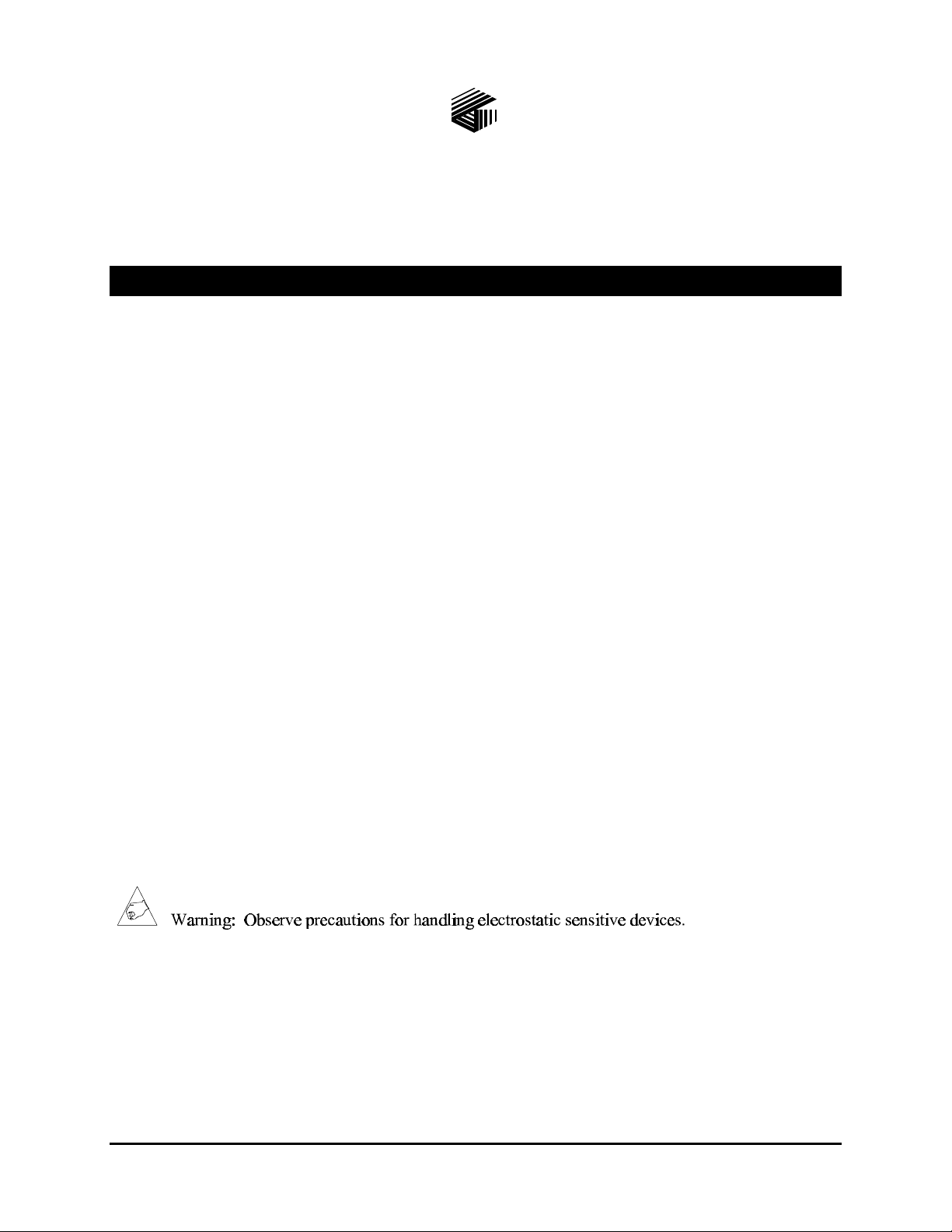
2. Remove the 7 screws securing the top panel and gently lift the cover exposing the attached speaker
cable and master display cable. See Figure 1 on page 2.
GAI-Tronics Corporation P.O. Box 1060, Reading, PA 19607-1060 USA
610-777-1374 n 800-492-1212 n Fax: 610-775-6540
VISIT WWW.GAI-TRONICS.COM FOR PRODUCT LITERATURE AND MANUALS
Page 2
Pub. 43003-012B
Model XCP0010A DC Control Kit Page: 2 of 4
3. Disconnect the speaker cable at the male-to-female connection point. Unplug the master display
cable from the top cover.
Figure 1.
4. Disconnect all plugs attached to the inner PC board mounting plate. See Figure 1. Then remove the 4
screws attaching the mounting plate to the base. This allows you to remove the mounting plate.
11/02
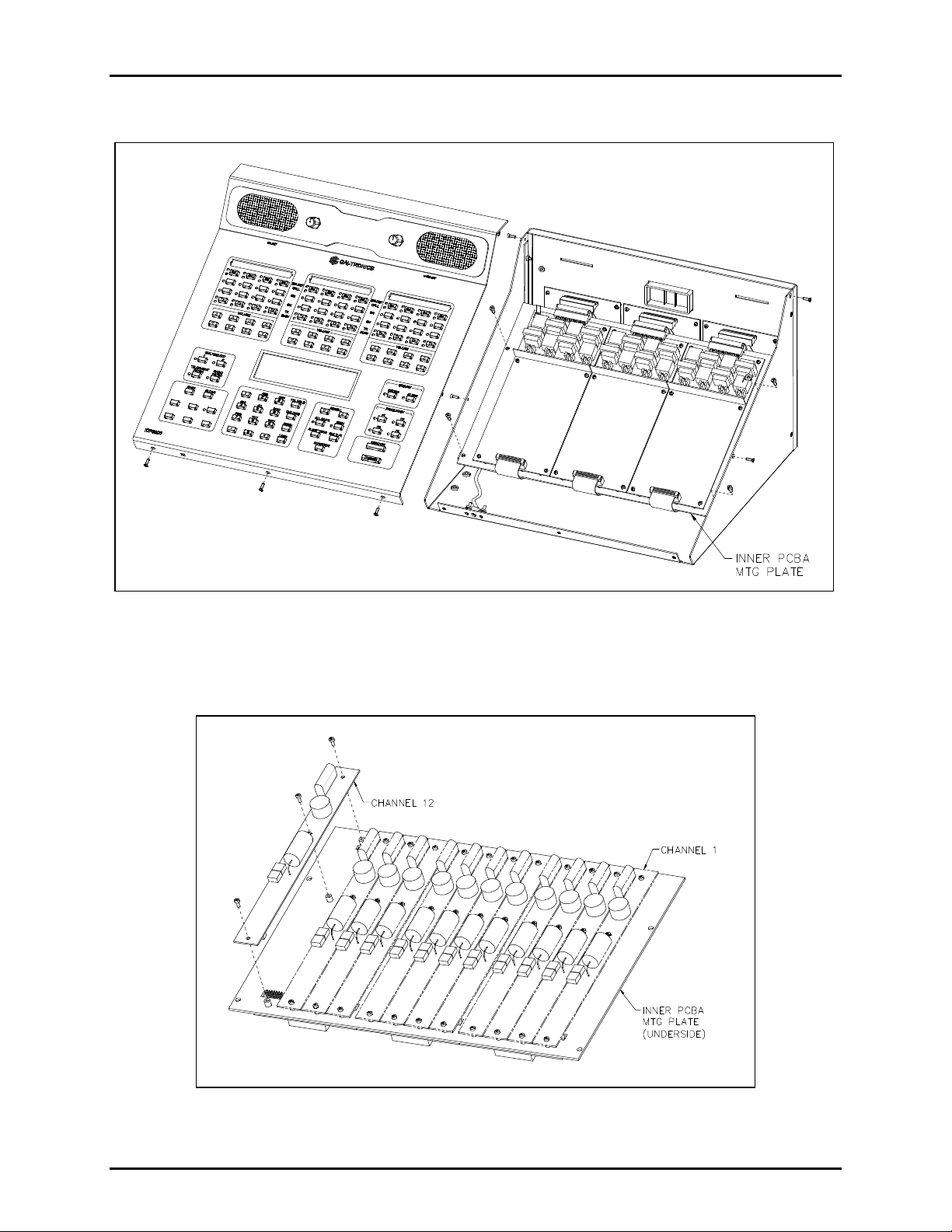
Figure 2.
Page 3

Pub. 43003-012B
Model XCP0010A DC Control Kit Page: 3 of 4
5. Mount the XCP0010A DC Control Option CDC PCBA to the appropriate slave PCBA (1, 2, or 3) and
channel (1, 2, 3, or 4 for each PCBA). The CDC PCBA must be mounted on the bottom side of the
slave panel.
6. Remove the shunt and connect the 2-pin connector P62X on the CDC PCBA to the appropriate
header on the slave PCBA (JU620, JU621, JU622 or JU623).
7. Connect the-pin connector P2X to the 14-pin header (P26, P27, P28, or P29) on the CSD PCBA.
8. Fasten the CDC PCBA to the inner PCBA mounting plate using the 3 supplied #4-40 screws. See
Figure 2.
9. After the PCBA has been properly mounted, you may reassemble the console by reversing the
disassembly procedure. Verify that all CSD-to-main board ribbon cables are properly positioned into
their protective guides and connected to their respective main board connectors as follows:
Channel Main Board Connector
1-4 P1
5-8 P2
9-12 P3
Main Board-to-CSD Slave Board Connectors
Note: The XCP0010A DC Control board has been factory-calibrated to provide the standard control
currents and does not normally require field adjustment.
10. Reconnect power to the ICP9000 Series Desktop Console.
After the console has been reassembled, it is necessary to program the console by editing the channel
parameters. Refer to your CARD Suite Software (XAC1000A) for specific programming instructions.
Also refer to the ICP9000 Series Desktop Console Operator’s Manual, 43004-016, for user instructions
on dc control operation.
ICP9000 Navigator Series MCU
1. Disconnect power from the ICP9000 Navigator Series MCU.
2. Remove the 10 screws securing the side cover panel and gently lift the cover exposing the attached
speaker cable and master display cable. See Figure 3 on page 4.
3. Disconnect all plugs attached to the inner PC board mounting plate. See Figure 3. Then remove the 4
screws attaching the mounting plate to the base. This allows you to remove the mounting plate.
4. Mount the XCP0010A DC Control Option CDC PCBA to the appropriate slave PCBA (1, 2, or 3) and
channel (1, 2, 3, or 4 for each PCBA). The CDC PCBA must be mounted on the bottom side of the
slave panel.
5. Remove the shunt and connect the 2-pin connector P62X on the CDC PCBA to the appropriate
header on the slave PCBA (JU620, JU621, JU622, or JU623).
6. Connect the-pin connector P2X to the 14-pin header (P26, P27, P28, or P29) on the CSD PCBA.
11/02
Page 4

Pub. 43003-012B
Model XCP0010A DC Control Kit Page: 4 of 4
Figure 3.
7. Fasten the CDC PCBA to the inner PCBA mounting plate using the 3 supplied #4-40 screws. See
Figure 2.
8. After the PCBA has been properly mounted, you may reassemble the MCU by reversing the
disassembly procedure. Verify that all CSD-to-main board connections are as follows:
Channel Main Board Connector
1-4 P1
5-8 P2
9-12 P3
Main Board-to-CSD Slave Board Connectors
Note: The XCP0010A DC Control PCBA has been factory-calibrated to provide the standard control
currents and does not normally require field adjustment.
9. Reconnect power to the ICP9000 Navigator Series MCU.
After the console has been reassembled, it is necessary to program the console by editing the channel
parameters. Refer to your CARD Suite software (XAC1000A) for specific programming instructions.
Also refer to the ICP9000 Navigator Series Operator’s Manual, pub. 43004-025, for user instructions on
dc control operation.
11/02
 Loading...