

Page 1

Pub. 43004-033A
GAI-TRONICS® CORPORATION
A HUBBELL COMPANY
Model XB001
Weatherproof Long-Life Battery Enclosure
Confidentiality Notice
This manua l is provide d sole ly as an operatio nal, installation, and ma inte nance guide and conta ins
sensitive business and t e chnical informatio n tha t is confidentia l and pr opri et ary to GAI- Tronics.
GAI-Tronics retains all intellectual property and other rights in or to the information contained herein,
and such information may only be used in connection with the operation of your GAI-Tronics product or
system. This manu al may not be dis clos e d in any form, in whole or in pa rt, direct ly or i ndir ectly, to a ny
third pa r ty.
General Information
The Model XB001 Weatherproof Long-Life Battery Enclosure is intended for use with the Model 13352,
13362, or 13372 Addressable Amplified Speaker Assemblies, the Model CP190 or CB191 RF Call Boxes
and/or t he SPK 200 Solar Pa ne l Int erfac e Kit. I t includes t he follo wing components:
Qty Description
1 Enclosure assembly
4
4 Washers
1 Wiring harness with weatherproof plug
1 Model 230 Mounting Kit
1 Model 40201-008 Battery, 12V, 18Ah
Screws, #10-32 × 1.125-inch
Recommended acces sori es:
GAI-Tronics Corporation 400 E. Wyomissing Av e. Mohnton, PA 19540 USA
610-777-1374 800-492-1212 Fax: 610-796-5954
ISIT WWW.GAI-TRONICS.COM FOR PRODUCT LITERATURE AND MANUALS
V
Page 2
Pub. 43004-033A
Model XB001 Weather pr oof Long-Life Battery Enclosure Page: 2 of 5
Installation
Mounting the Enc losure
1. Remove the four screws from the front of the enclosure. Open the front cover to the left and pull
straight out until the hinge pins separate from the rear section. Set the front door of the enclosure
aside.
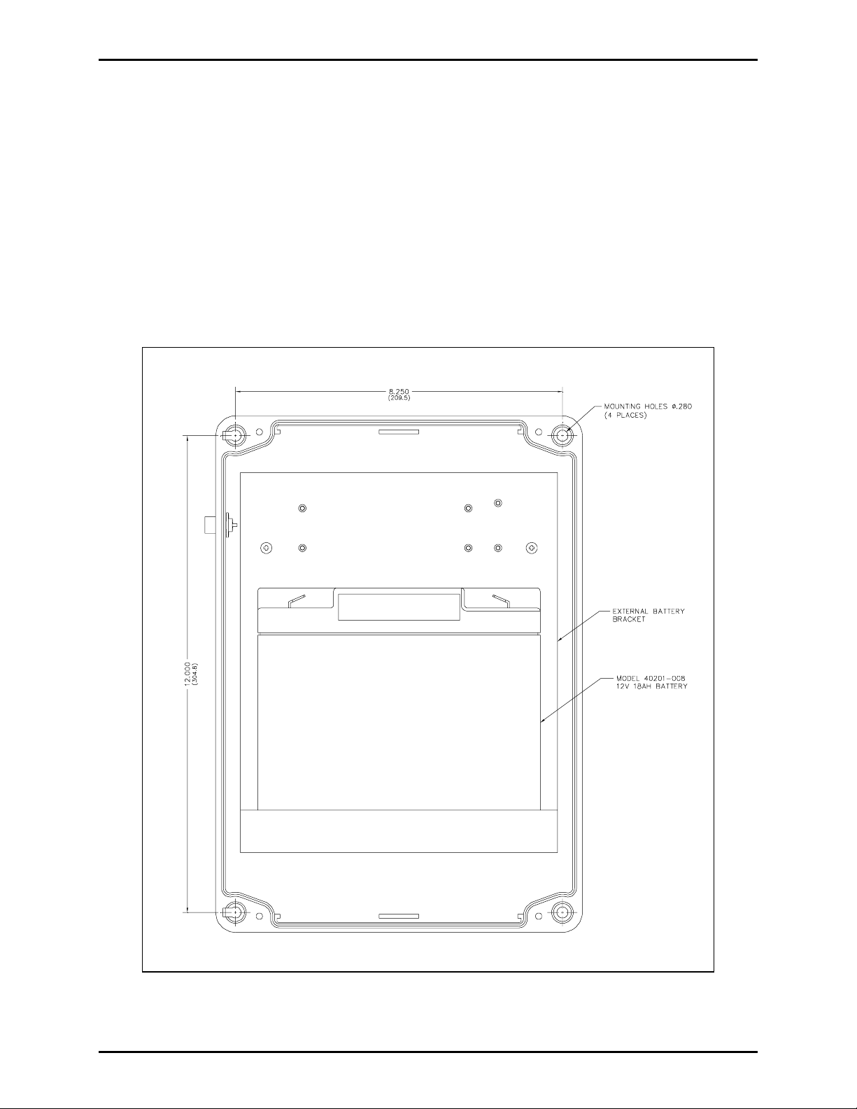
2. Secure the rear section of the external battery enclosure to the desired surface with screws or
appropriate customer-provided fasteners. Each enclosure mounting hole is 0.280 inch in diameter
allowing the use of 1/4-inch diameter screws. Refer to Figure 1. The enclosure can also be mounted
to a Model 230 Pole Mounting Kit for pole or surface mounting. Four mounting screws are provided
with the pole mounting kit.
Figure 1. Rear half of the en c losure
\\s_eng\gtc proddoc s \ radio produc ts-current release\43004\ 43004-033a\ 43004-033a. doc
08/08
Page 3

Pub. 43004-033A
Model XB001 Weather pr oof Long-Life Battery Enclosure Page: 3 of 5
3. Place the No. 40201-008 battery onto the mounting panel in the enclosure. Refer to Figure 2. The
positive battery terminal should be on the right side when facing the enclosure.
Figure 2. Exploded view of the external battery enclosure
\\s_eng\gtc proddoc s \ radio produc ts-current release\43004\ 43004-033a\ 43004-033a. doc
08/08
Page 4

Pub. 43004-033A
Model XB001 Weather pr oof Long-Life Battery Enclosure Page: 4 of 5
4. Connect the wiring harness’s quick-connect fastons to the battery terminals: red to positive, black to
negative. Refer to Figure 3.
5. Return the door to the rear section by inserting the hinge pins and pushing into place, closing the
door, and re-installing the four screws using 16 to 20 inch-pounds of torque.
Figure 3. Interconnection Diagram
\\s_eng\gtc proddoc s \ radio produc ts-current release\43004\ 43004-033a\ 43004-033a. doc
08/08
Page 5

Pub. 43004-033A
Model XB001 Weather pr oof Long-Life Battery Enclosure Page: 5 of 5
Connecting to the A ddressable Amplified Speak er
1. The Addressable Speaker is shipped with only two of the six screws securing the front section to the
rear. Back out the two screws and separate the two sections, carefully setting aside the front section.
Refer to GAI-Tronics Pub. 43004-030 for more detail.
2. Insert the lugged end of the (provided) weatherproof plug cable assembly through the existing cable
bushing located on the bottom of the speaker housing’s rear section. Wrap electrical tape around the
cable where it enters the bushing until it has a minimum diameter of 0.25 inch, allowing
approximately 10 inches of cable to remain inside the speaker housing. Tighten the bushing around
th e cable.
3. Connect the 3/16-inch male quick-connect fastons from the weatherproof plug cable assembly to the
existing 3/16-inch fastons already attached to the speaker’s 11-point terminal strip plug. It is
extremely important to follow the color code noted in Figure 3. Failure to matc h red t o red and
black to bl a ck could result in damaged circ uitry.
4. Mount the rear section of the enclosure within two feet of the battery box and attach the speaker front
as described in Pub. 43004-030.
5. Insert the speaker cable plug into the receptacle located on the upper left side of the battery enclosure.
Connecting to the RF C all Box
1. Install the customer-provided weather-tight cable bushing in the bottom (right side) of the Call Box
rear section.
2. Remove the lugs from the weatherproof plug assembly, strip the wire insulation 1/8 inch, and insert
the cable through the previously installed cable bushing. Allow enough cable inside the enclosure to
connect the power input terminal strip (P5), located on the PCBA, with the door open. Secure the red
and bl ack w ires as noted in Figure 4 b el ow:
Figure 4.
3. Close the C all Box door and tighten the screws using 16 to 20 inch-pounds of torque.
4. Mount the External Battery enclosure close enough to the RF Call Box mounting location to allow the
plug cable assembly to be connected to the receptacle located on its upper left side.
\\s_eng\gtc proddoc s \ radio produc ts-current release\43004\ 43004-033a\ 43004-033a. doc
08/08
 Loading...