

Page 1

Pub. 43004-026C
GAI-TRONICS® CORPORATION
A HUBBELL COMPANY
Model XAAB002A
Audio Accessory Box
Installation and Service Manual
GAI-Tronics Corporation P.O. Box 1060, Reading, PA 19607-1060 USA
610-777-1374 800-492-1212 Fax : 610-796-5954
ISIT WWW.GAI-TRONICS.COM FOR PRODUCT LITERATURE AND MANUALS
V
Page 2

CONFIDENTIALITY NOTIC E
This manual is pr ovided s olely as a n op erat ional, installation, and maintenance guide and contains sens itive
bus ines s and t echnic al infor ma tion tha t is confident i al and p roprietary to G AI-Tronics. GAI-Tronics
retains a ll intellectual pr operty and other rights in or to t he inf ormation c ontained herein, and s uch
informa tion may only be used in connection wit h the operation of you r GAI- Tronic s pr oduct or system.
This ma nual may not be disclosed in any form, in whole or in p art, dir ec tly or indirectly, to any t hird pa rty.
COMPUTER SOFTWARE COPYRIGH T S
This produ c t contains cop yrighted computer programs stor ed in s emicondu c tor memory. These p rograms
ar e c opyright ed b y GAI-T ronics Corp oration and ma y not be rep roduced in any for m without exp ress
writ ten permission from GAI -Tronics.
WARRANTY
GAI-Tronics warrants for a period of one (1) year from the date of shipment, that any GAI-Tronics equipment supplied
hereunder shall be free of defects in material and workmanship, shall comply with the then-current product specifications and
product literature, and if applicable, shall be fit for the purpose specified in the agreed-upon quotation or proposal document. If
(a) Selle r’s goods prove to be defe ctive in w orkma nship a nd/or material under normal and proper usage, or unfit for the
purpose specified and agreed upon, and (b) Buyer’s claim is made within the warranty period set forth above, Buyer may return
such goods t o G AI-Tronics’ n earest depot repai r facility, freight prepaid, at which time they will be repaired or replaced, at
Seller’s option, without charge to Buyer. Repair or replacement shall be Buyer’s sole and exclusive remedy, and the warranty
period on any repaired or replacement equipment shall be one (1) year from the date the original equipment was shipped. In no
event shall GAI-Tronics’ warranty obligations with respect to equipment exceed 100% of the total cost of the equipment
supplied hereunder. The applicability of any such third-party warranty will be determined solely by GAI-Tronics.
Services. Any services GAI-Tronics provides hereunder, whether directly or through subcontractors, shall be performed in
accordance with the standard of care with which such services are normally provided in the industry. If the services fail to meet
the applicable industry standard, GAI-Tronics will, for a period of one (1) year from the date of completion, re-perform such
services at no cost to the Buyer. Re-performance of services shall be Buyer’s sole and exclusive remedy, and in no event shall
GAI-Tronics’ warranty obligations with respect to services exceed 100% of the total cost of services provided hereunder.
Limita ti ons/Exclusions. The warranty on any equipment supplied hereunder is subject to Customer’s use in compliance
with applicable FCC regulations and manufacturer specifications. The warranties herein shall not apply to, and GAI-Tronics
shall not be re sponsib le for, any dama ge to the goods or f ailure of th e services suppl i ed her eunder, t o the extent caused by
accident, misuse, abuse, neglect, system design, product modification, failure to follow instructions contained in the product
manual, repair, or attempted repair by anyone not authorized by GAI-Tronics, improper installation, installation of parts that do
not conform to the quality or specifications of the original parts or accessories, damage or loss occurred during shipment, or any
unit which is not new when sold or upon which the serial number has been defaced, modified or removed. The warranty does
not extend to damage incurred by natural causes including Force Majeure. The warranty does not cover microprocessors if
failure is due to static damage or application of improper voltage.
THE WARRANTIES AND REMEDIES
CONTAINED HEREIN ARE IN LIE U OF AND EXCLUDE ALL OTHER WARRANTIES AND REMEDIE S,
WHETHER EXPRESS OR IMPLIED BY OPERATION OF LAW OR OTHERWISE, INCLUDING ANY
WARRANTIES OF MERCHANTABILITY OR FITNESS FOR A PARTICULAR PURPOSE.
Operational and Maintenance Procedures
modification of the equipment provided hereunder, or use of unqualified maintenance or service technicians will severely
impair the operational effectiveness of the entire communication system. Buyer hereby agrees to indemnify, defend and hold
GAI-Tronics harmless from and against any and all third party claims arising, in any manner, out of: (a) Buyer’s neglect of the
equipment; (b) Buyer’s use of technicians not authorized by GAI-Tronics to service the equipment; or (c) Buyer’s improper use
or modification of the equipment or failure to follow the operational and maintenance procedures provided with the equipment.
. Buyer acknowledges that any improper use, maintenance, or
Limitation of Liability /Damages. In no event (even should circumstances cause the exclusive warranties and remedies
set forth in the Warranty section to fail of their essential purpose) shall either party be liable for any indirect, incidental, special
or consequential damages (including, but not limited to, loss of use, loss of anticipated profits, or damages arising from delay)
whether such claims are alleged to have arisen out of breach of warranty, breach of contract, strict or absolute liability in tort,
or other act, error or om iss ion, or fr om any oth er cause w hat soever, or any combina tion of the f oregoi ng.
11/06 Publication 43004-026C i
Page 3

Table of Contents
FOREWORD ....................................................................................................................................................... 1
SCOPE OF MANUAL..............................................................................................................................................1
NOMENCLATURE................................................................................................................................................. 1
ORDERING REPLACEMENT PARTS.........................................................................................................................1
SERVICE AND REPAIR ..........................................................................................................................................1
FEATURES AND BENEFITS OF THE AUDIO ACCESSORY BOX.................................................................................... 2
FCC INTERFERENCE WARNING............................................................................................................................ 2
SAFE HANDLING OF CMOS INTEGRATED CIRCUIT DEVICES .................................................................................. 3
PERFORMANCE SPECIFICATIONS........................................................................................................................... 4
DESCRIPTION....................................................................................................................................................5
PHYSICAL DESCRIPTION ......................................................................................................................................5
FRONT PANEL ..................................................................................................................................................... 5
REAR PANEL .......................................................................................................................................................5
CONNECTOR PIN DESCRIPTIONS........................................................................................................................... 6
J1, 8-pin Output Connector, Mot orola St andard, Mi rrored Connector........................................................... 6
J2, GAI-Tronics Ixx Handset Output, Mirrored Connector............................................................................. 6
J3, Desk Microphone, 8-pin Modular, Motorola St andard.............................................................................7
J4, GAI-Tronics Handset, 4-pin Modular Connector ...................................................................................... 7
J5, Boom Microphone Audio, R CA -ty pe , Phono-Jack Connec t or...................................................................7
J6A and J6B, Headset Dual 1/4-i nc h Tele phone Plug, Carbon Standard Connec tor ...................................... 8
J7, Alternate Headset , 4-pin Modul ar, Carbon Standard Connec t or .............................................................. 8
J8, Power Input, 2.0 mm Barrel Jack Connector............................................................................................ 8
J9, 6-pin Modular Alternate Output, Ke nwood Standard Connector ..............................................................9
J10, Telephone Handset I/O, Carbon Standard Connect or............................................................................. 9
P1, Footswitch Connector...........................................................................................................................10
ACCESSORIES.................................................................................................................................................... 10
OPERATION.....................................................................................................................................................11
FUNCTIONAL DESCRIPTION................................................................................................................................11
FUNCTIONS ....................................................................................................................................................... 11
Push-to-Talk (PTT - Radio Key-up).............................................................................................................. 11
Monitor.......................................................................................................................................................11
Mute............................................................................................................................................................ 11
Off-Hook Output (J1 – pin 2)....................................................................................................................... 12
TELEPHONE INTERFACE..................................................................................................................................... 12
INSTALLATION...............................................................................................................................................13
PLANNING THE INSTALLATION........................................................................................................................... 13
MECHANICAL RECEIPT INSPECTION.................................................................................................................... 14
MOUNTING....................................................................................................................................................... 14
EQUIPMENT REQU IRED...................................................................................................................................... 14
Test Equipment............................................................................................................................................ 14
Documentation ............................................................................................................................................ 14
11/06 Publication 43004-026C ii
Page 4

Table of Content s Model XAAB002A Audio Accessory Box
CABLE INSTALLATION SAFETY CONSIDERATIONS ............................................................................................... 14
POWER CONNECTIONS....................................................................................................................................... 15
PROGRAMMING SETTINGS..................................................................................................................................15
TROUBLESHOOTING..................................................................................................................................... 17
TROUBLESHOOTING THE MODEL XAAB002A AUDIO ACCESSORY BOX...............................................................17
MAIN CIRCUIT BO ARD.................................................................................................................................. 19
SCHEMATICS...................................................................................................................................................21
DEFINITIONS AND ACRONYMS................................................................................................................... 25
11/06 Publication 43004-026C iii
Page 5

Foreword
Scope of Manual
This manual offers descriptive data and service information for the GAI-Tronics Model XAAB002A Audio
Accessory Box. Service diagra ms and pr inted circuit board det ails a re a p art of this service manu al.
Nomenclature
The mo del numb er, located on the nameplate o n the b otto m, specifically i den tif i es GAI -T ronics equipment.
If a dditional op tions a re order ed, the opt i on will b e identi f ied on the circuit board.
Ordering Replacement Parts
When ordering replacement par ts o r requestin g eq uipment inf o rma tion, pl eas e i n clude the co mplete
identification number. This applies t o all components , kits, and c hassis. If the component part number is
not known, the order should inclu de t he nu mber of the chass is or kit of which it is a pa rt and suf ficient
descri ption of t he desi red component to identify it. Order pa rts f rom:
Customer Service
GAI-Tronics Cor poration
400 E. Wyomissing Ave.
Mohnton, PA 19540
US: 800-492-1212
Outside US: 610-777-1374
Service and Repair
Inoperative or ma lfunctioning equ ipment should b e returned to the fa c tory for rep air. Plea se call
1-800-492-1212 to obtain a Return Authorization number, published rep air prices, and shipping
instructions.
OTE: A purchase or der or credit card nu mber is required prior to pr oc es sing non-warr anty repairs.
N
1 11/06
Page 6
Foreword Model XAAB002A Audio A ccessor y Box
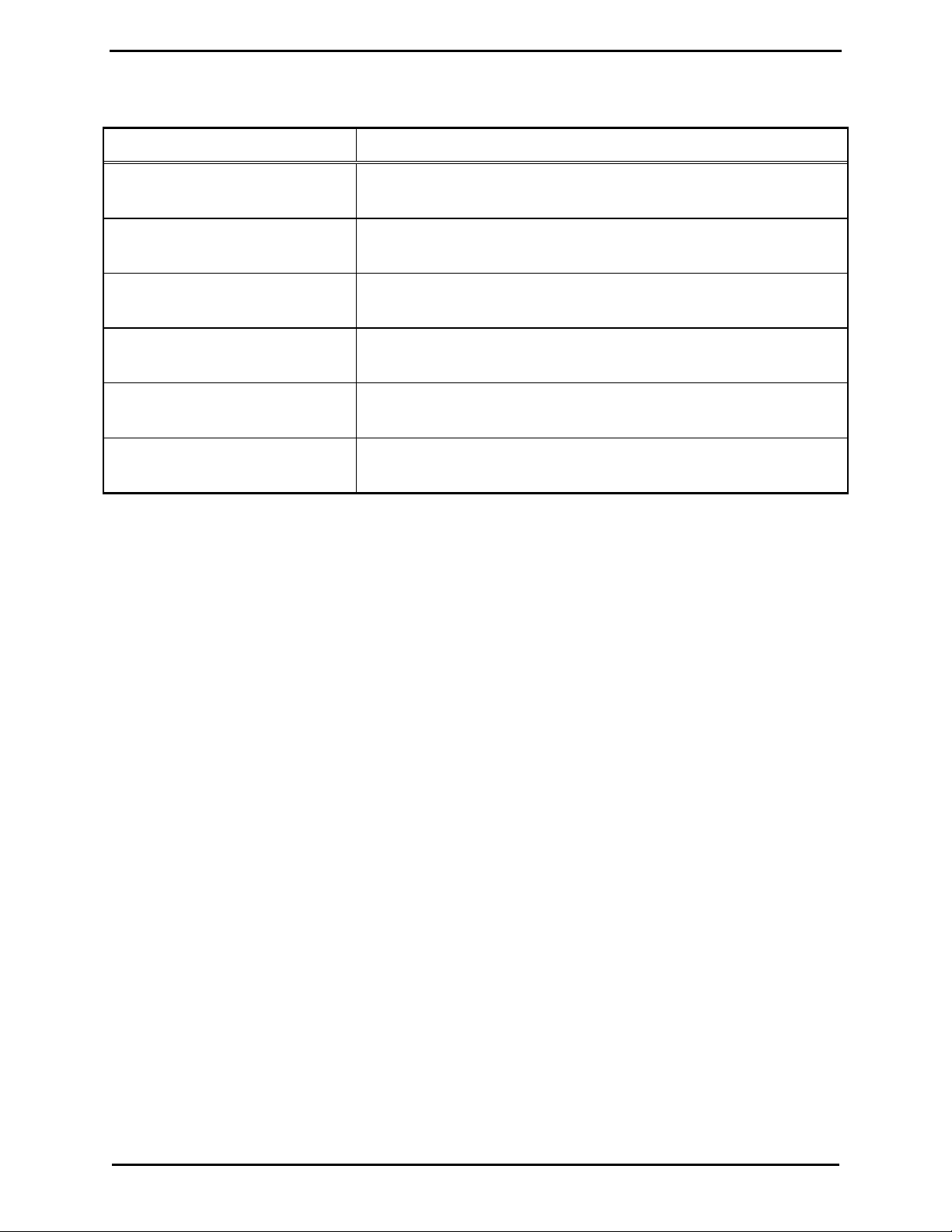
Features and Benefits of the Audio Accessory Box
Feature Benefit
Mult iple dispa tch microp hones are
possible
Effortless c hanging of micr ophones preferr ed b y dif f erent shif t
operators.
Ra dio/telephone inter face Allows disp atch over radio and t elephone s imu ltaneous ly with the
same headset
Small, compact size Fits easily into most set - up configu rations and uses lit tle desk top
space
Effic ient , st reamlined microp hone
Eliminates messy, jury-r igged microphone hook-up s
connections
Top cover can also be used as a
Allows multiple mounti ng c onf igu rations for customized set-up
mounting brac ket
Use with remote desktop controller
or stand- alone.
Pr ovides f lex ibility by connecting directly to the radio for stationary
or mobile ap plications.
FCC Interference Warning
The F CC requires that manuals per taining t o Class A a nd Clas s B computing devices must contain
war nings ab out pos sible interference wit h loc al res ident ial radio and TV recep tion. This wa rning reads as
follows:
OTE: This equipment has been tested and fou nd to comply with t he limits for a Clas s A digita l device,
N
pursuant t o Part 15 of the FCC R ules. These limits are designed t o provide r easona ble protection a gainst
harmful interf erenc e wh en the equipment is o per ated i n a commercial envi ronment. This equipment
generates, u ses, and ca n radiate r adio fr equ ency ener gy and, if not installed and u sed in accordance with the
instruct ion manual, may cause harmful interfer ence to ra dio c ommunications . Operat ion of this equipment
in a r es ident ial area is likely t o c ause harmful interference in which case the us er will be required to cor rect
the in ter feren ce at his o wn expense.
11/06 2
Page 7

Model XAAB002A Audio Accessory B ox Foreword
Safe Handling of CMOS Integrated Circuit Devices
Many of the integrated circuit devices used in communications equip ment are of the Complementary Metal
Oxide Semicondu c tor (CMOS) type. Beca use of their high open circuit impedance, CMOS integrated
circ uits are vu lnerab le t o damage fr om s tat ic c harges . Care must be taken handling, shipping, and
servicing them and the as semblies in which they are used.
Even though prot ection devices a re pr ovided in C MOS integra ted circ uit inputs, the protect ion is effective
only aga inst over voltage in the hu ndreds of volt s range such as is encountered in an operating s ystem. In a
system, circu i t elements distribute st at i c charg es a n d load the C MOS circuits, d ecreasing th e chan ce of
damage. However, CMOS cir c uits c an be da maged by improper ha ndling of the modules, even in a
system.
To avoid damage t o c ircuits, observe t he following handling, shipping, and s ervicing precautions:
1. Pr ior to a nd while servicing a c ircuit module, part icularly after moving within the service area,
momentarily t ouch bot h hands to a bare metal, earth-grounded surfa c e. This will discharge any stat ic
charge that may ha ve accumulated on the p erson doing the s ervicing.
OTE: Wearing a c onductive wrist strap will minimize static bu ild- up during servicing.
N
2. Whenever possible, avoid tou c hing any electr ic ally conduc tive parts of the circ u i t module with your
hands.
3. Power down the unit b efore inst alling or removing the circ uit module.
4. When servicing a circuit module, avoid carpeted areas, dry environments, and certain types of cl othing
(silk, nylon, etc. ) because they contribu te to st atic build-up. S imilarly, disconnect t he test probe prior
to removing the ground lead.
5. All electric ally power ed test equipment should b e grounded. Apply the ground lead f rom the tes t
equipment to the circ uit module before connecting t he test probe.
6. If a c i rcuit module is removed from t he s ystem, it is desirable to lay it on a c onductive surface (su c h as
a sheet of alu minum foil) which is connect ed t o ground t hrough 100k of resistance.
7. When soldering, be su re the solder ing iron is grounded, and has a grounded tip .
8. Pr ior to connecting jumpers, replac ing c ircuit components , or touching CMOS pins (if this becomes
necessa ry in the r ep lacement of a n integra ted circuit device), be sure to discharge a ny sta tic bu ild- up as
descri bed in procedu re 1. Since voltage differences c an exist across the human body, it is
recommended that only one hand be us ed if it is necess ary to touc h pins on the CMOS device and
associated board wiring.
9. When replacing a CMOS integrated circuit device, leave the device in its c onductive r ail container or
conduct ive foam until it is to be ins erted into the p rinted circuit module.
10. All low impedanc e test equipment (su c h as p ulse genera tors, etc .) shou ld be connected to CMOS device
input s after power is ap p lied to the CMOS circuit ry. Similarl y, suc h low impeda nc e equip ment should
be disconnected before p ower is t urned off.
11. Rep lacement modules ship ped sepa rat ely f rom the fac tory will be p ackaged in a conductive material.
Any modules being transpor ted from one area t o another should b e wrap ped in a similar material
(aluminum foil may b e us ed). Ne ver use non-c onduc tiv e material f or pa c kaging these modules.
3 11/06
Page 8

Foreword Model XAAB002A Audio A ccessor y Box
Performance Specifications
Color................................................................................................................................................ Black
Physical size.......................................................................................... 1.55 H × 6.40 W × 4.25 D inches
Shipping weight................................................................................................................................ 3 lbs.
Power input ...................................................................................... 9.0 to 16.0 V dc, 100 mA, maximum
Receive audio input..................................................................................................... 100 mV ac nominal
Transmit audio output............................................................................. 80 mV ac nominal into 600 ohms
Environment:
Ambient temperature, operation ............................................................................................ 0º C to 60º C
Ambient temperature, storage........................................................................................... -40º C to 100º C
Ambient humidit y, non-condensing...................................................................................................... 90%
Microphone inputs with respect to 80 mV ac output:
Desk mic, selectable............................................................................................. 25 mV ac or 800 mV ac
Ixx Handset, nominal................................................................................................................. 25 mV ac
Boom mic, selectable....................................................................... 200 µV ac or 850 µV ac or 15 mV ac
Headset mic, selectable........................................................................................ 25 mV ac or 800 mV ac
Nominal microphone gain selections:
Desk mic ...................................................................................................................... +10 dB or –20 dB
Ixx Handset...................................................................................................................... +10 dB or unity
Boom mic..................................................................................................... +51 dB or +40 dB or +15 dB
Headset mic.................................................................................................................. +10 dB or –20 dB
Noise floor (S+N/N)..........................Greater the -45 dB below rated output except high gain on boom mic
Logic output levels............................................................................................ 5-volt, CMOS-compatible
Audio distortion............................................................................................................Less than 2% THD
11/06 4
Page 9
Description
Physical Description
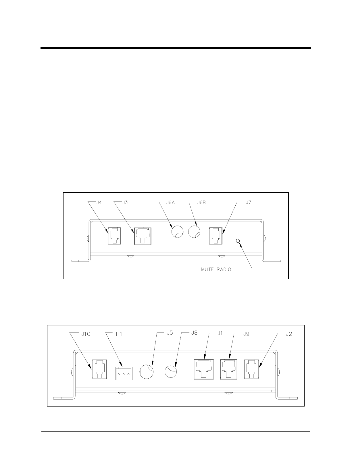
The GAI-Tronics Model XAAB002A Audio Accessory Box measures 1.55 H × 6.40 W × 4. 25 D inches.
It contains f i ve connectors and a n optiona l mu te ra dio push b utt on on the front panel, and t he rear panel
contains six connectors. A seventh connector, J10, is a n available option. It is shipped with a 9-volt dc
wall plug-in power supply, a 7-foot RJ45 male-male 8-pin modular cable (mirror-connected), a 6-foot 4- pin
retrac tile cord, and a dc power c onnec tor.
The XAAB002A also includes a cover that can be used as a bracket in specific mounting arrangements
descri bed in the Inst allation section. Optional access ories, such a s microp hones , headsets, footswit c hes ,
etc. mu st be ordered separately.
Front Panel
Refer to the figu re below for the locations of the connectors a nd optiona l mu te pus h button on the front
panel of the accessory box.
Model XAAB002A Audio Accessory Box - Front Panel
Rear Panel
The r ear p anel of the a c c es sory b ox is shown below. Not e t hat connector J10 is optiona l.
Model XAAB002A Audio Accessory Box - Rear Panel
5 11/06
Page 10

Operation Model XAAB002A Audio A ccessor y Box
Connector Pin Descriptions
J1, 8-pin Output Connector, Motorola Standard, Mirrored Connector
J1 is the main out put c onnector to the radio, a console, or an Advanced desk set (towards radio). The
pin-out is mirrored with resp ect to a Motorola s tandard 8 - pin modular mic jack. See the pi n- out below.
N
OTE: Mirrored pin-out (op posite of pin-to-pin) is u sed on outp ut connectors so a s tandard off-the-shelf
male-male modular cable will connect properly.
Table 1. J1, 8-Pin Output Connector Pin-out
Pin No. Function
1 RX audio from ra dio to hands et and heads et.
Nominal level = 100 mV ac
2 Handset off- hook logic low output towards radio (or c onsole)
3 PTT logic low output towards radio
4 TX audio ou tput towa rds radio
Nominal level = 80 mV a c
5 Audio ground
6 Monitor logic output towards radio
7 Not connected
8 DC p ower input (from some radios or consoles)
J2, GAI-Tronics Ixx Handset Output, Mirrored Connector
J2 is the GAI-Tronics hands et “t hrough-f unction” outpu t connector. The accessory box can be placed
electric ally between the handset and its r es pective desk set . This enables the audio access ory box to control
handset functions. J2 is mir rored for eas y c onnec tion to the desk set handset jac k. T he pi n- out for J2 is
shown below.
OTE: Mirrored pin-out (op posite of pin-to-pin) is u sed on outp ut connectors so a s tandard off-the-shelf
N
male-male modular cable will connect properly.
Table 2. J2, GAI-Tronics Handset Output Pin-out
Pin No. Function
1 Audio ground
2 Handset analog logic fu nc tions
3 RX audio from radio. Nominal level = 100 mV ac
4 TX audio t owards radio. Nominal level = 2 5 mV ac
11/06 6
Page 11

Model XAAB002A Audio Accessory B ox Operation
J3, Desk Microphone, 8-pin Modular, Motorola Standard
J3 is the connector for the desktop microphone, Model XDM002A. The pin-out matches the Motorola
standard 8-p in modu lar des k mic.
Table 3. J3 Desk Mic Connector Pin-out
Pin No. Function
1 Not connected
2 Not connected
3 Monitor logic inpu t from desk mic
4 Audio ground
5 TX audio t owards radio. Nominal level = 8 0 mV ac
6 PTT logic low output towards radio
7 Not connected
8 RX audio from radio. Nominal level = 100 mV ac
J4, GAI-Tronics Handset, 4-pin Modular Connector
J4 is the connector for the GAI-Tronics handset.
Table 4. J4 GAI-Tronics Handset Connector Pin-out
Pin No. Function
1 TX audio t owards radio. Nominal level = 2 5 mV ac
2 RX audio from radio. Nominal level = 100 mV ac
3 Handset analog logic fu nc tions
4 Audio ground
J5, Boom Microphone Audio, RCA-type, Phono-Jack Connector
J5 is an RC A- type au dio jack that is used as the connector f or a boom, a Model XGM002A Gooseneck
Microphone, or a M odel X D M003A Desktop Mic.
Table 5. J5 Boom Microphone Audio, Phono-Jack Connector Pin Function Descriptions
Pin Description Function
Center pin TX audio inp u t
Out er shield Audio ground
7 11/06
Page 12

Operation Model XAAB002A Audio A ccessor y Box
J6A and J6B, Headset Dual 1/4-inch Telephone Plug, Carbon Standard Connector
J6A and J6B are hea dset connect ions for ‘ c arbon standard’ (twin 1/4-inch) phone plugs . Thes e c onnectors
will accommodat e low impedanc e, electret, or amplified-dyna mic type headset s such as M odel XH S0003A
with XCC003A Coiled Cord. PTT on the ring terminals is also supported.
Table 6. J6A and J6B Headset Dual Telephone Plug Connector Pin Function Descriptions
Pin Description Function
Tip s TX audio t owards radio
Sleeves RX audio from radio
Rings PT T logic s ens e
J7, Alternate Headset, 4-pin Modular, Carbon Standard Connector
J7 is par allel to J6 /J7. This is the 4- pin modular headset c onnection for the GAI-T ronics M odel X H S002A
Heads et. The pin descript ions are shown in the t able b elow.
Table 7. J7 Alternate Headset Connector Pin Function Descriptions
Pin Description Function
1 Red wire TX audio
2 White wire RX audio
3 Green wire RX audio
4 Black wire TX audio
J8, Power Input, 2.0 mm Barrel Jack Connector
J8 is a barrel-type power connector for ex terna l 9 to 16 V dc. The center post is positive. T his is the
preferred power input for optimum performance.
Table 8. J8 Power Input Pin-out
Pin Description Function
Center pin 9–16 V dc input, positive
Out er ba rrel Ground, negative
11/06 8
Page 13

Model XAAB002A Audio Accessory B ox Operation
J9, 6-pin Modular Alternate Output, Kenwood Standard Connector
The J9 is the al terna te main output c onnector in a mirrored 6-p in mirrored jack t hat is c onnected to
plug- and-play with K enwood radios .
Table 9. J9 Modular Alternate Output Pin-out
Pin No. Function
1 Monitor logic output towards radio
2 TX audio ou tput towa rds radio.
Nominal level = 80 mV a c
3 Audio ground
4 PTT logic low output towards radio.
5 Logic ground
6 Not connected
J10, Telephone Handset I/O, Carbon Standard Connector
NOTE: Pin-out ma tches t elephone handset end.
The J10 is the handset output connect or where a carbon standard t elephone handset c ord is pl ugged in for
the telephone dispat c h option. The headset hear s the au dio from the t elephone p arty as well as the radio.
The telephone off - hook and dialing must be done manually by the ra dio user.
Table 10. J10 Telephone Handset I/O Pin-out
Pin Description Function
1 Black wir e TX audio –
2 Green wir e RX audio
3 White wire RX audio
4 Red wire TX audio +
9 11/06
Page 14

Operation Model XAAB002A Audio A ccessor y Box
P1, Footswitch Connector
P1 is the connection f or the GAI- Tronic s Model XF S002A Footswitch. It supports the monitor and PTT
functions.
Table 11. P1 Footswitch Connector Pin-out
Pin No. Function
1 Footswitch P TT ( transmitter key-up) logic low inpu t
2 Logic ground
3 Footswitch monitor logic low input
Accessories
Description Part No.
Desktop Microphone XDM002A
Desktop Microphone, H eavy-duty XDM003A
Headset XHS002A
Headset (requires XCC003A Coiled Cord) XHS 003A
Coiled Cord (with PTT switch) XCC003A
Gooseneck Mi c rophone, Lightweight XGM002A
Gooseneck Mi c rophone, Heavy-du ty XGM003A
Footswitch XFS002A
DC Power Supply (replacement) XPS002A
11/06 10
Page 15

Operation
Functional Description
The GAI-Tronics Model XAAB002A Audio Accessory Box is an appliance for consolidating various audio
input /out put devices ass oc iated wit h two-way dispa tch radio ser vic e. Audio paths throu gh the device are
enabled a s needed depending on the device being used a t any given time, and are configured for the optima l
signal levels assoc iated wit h currently available microphones, heads et s and handsets .
Several operating parameters vary the signal levels and logica l behavior of the various devices . They are
selecta ble with pr ogramming switc hes .
After initial installation of the Audio Accessory Box, no user interfa c e is requir ed. For inf ormation on the
operation of the var i ous accessories, refer to the associated user manu als.
Functions
Push-to-Talk (PTT - Radio Key-up)
Push-to-talk can be initiated from the paddle on t he desk mic, the TRANSMIT bar on the desk set, handset
PT T bar, the footswitch, or a PTT bu tton a ssociated with a headset. PTT is sensed individua lly at eac h
mic connector, a nd this a c tion rou tes the t ransmit au dio throu gh the path as sociated with that t yp e of mic.
See Table 12 . Ju mper Settings on page 15 in the Description section.
Monitor
Monitor is operat ed from the sa me sou rces as a bove. T his funct i on is used primar ily in analog radio where
two or more radio systems share a common channel frequency. The monitor pedal on the footswitc h c an
also be used to momenta rily mute audio coming from the telephone pa rty. See Programming Settings in the
Installation section.
Mute
The optional mut e s witch on the front panel momentarily mutes radio receive audio to the hea dset.
11 11/06
Page 16

Operation Model XAAB002A Audio A ccessor y Box
Off-Hook Output (J1 – pin 2)
The off-hook output loc ated on J1 (8-pin output c onnector) is as sert ed when either the ha ndset connected to
the J4 ( G AI-Tronics handset c onnector) is ta ken off -hook, or when a headset is c onnected to J6A and J 6B
(headset dual ¼- inc h telephone plug). This s i gnal is used by the au dio accessory box to select the correct
microphone and may be used to route audio ap p ropriately in the connected u nit. When a GAI-T ronics
handset is not connected to J4 or is not able to b e p l aced on-hook, it ap pear s tha t the handset is off - hook to
the au dio accessory b ox. Therefor e, when not us ing a GAI-Tr onic s hands et , the internal ju mper, J U1, must
be in.
Always allow a short delay befor e speaking to allow t ime for the radio cha nnel t o be esta blished. The
TRANSMIT button or handset PTT bar must be held down while talking to the radio u ser a nd released to
listen. When the tr a nsmission is completed, the
TRANSMIT LED ex tinguishes and the desk s et returns to
the receiv e mod e.
Telephone Interface
This f eature allows the operator to use a common headset/ microphone for both radio and telephone
operation. N o telephone-to-radio pat c hing will occ ur. The r adio communication ca n be muted dur ing a
telephone communication by pressing the
MUTE RADIO push bu tton on the u nit’s f ront p anel.
OTE: The telephone must b e in off-hook mode for t he headset t o be active.
N
11/06 12
Page 17

Planning the Installation
Installati on
Sample installation diagrams for the XAAB002A when used with desktop controllers
Sample installation diagram for the XAAB002A when used directly with radio
13 11/06
Page 18

Installation Model XAAB002A Audio A ccessor y Box
Mechanical Receipt Inspection
The XAAB002A Audio Accessory Box is shipped in a cardboard container with inserts. Thoroughly
inspect it as soon as possib l e after deliver y. In-t ransit da ma ge s hould be immediately rep orted to the
tr ansp ortation company.
Mounting
The Audio Ac c essor y B ox can sit on a desktop or ca n be mounted to the side or under th e desk by means of
mounting screws through the top cover piece. In this case, the chassis bottom piece is rotated 180° and
secured ups ide down into the cover after the cover has b een mount ed u nder the desk or ta bletop.
Equipment Required
Test Equipment
• RF service monitor
• #1 Phillips screwdriver
• 1/8-inch flat blade screwdriver
Documentation
• instruction manuals f rom optional accessor i es
• these insta llation ins tru c tions
Cable Installation Safety Considerations
Inter c onnecting, communications , and Class 2 dc power cables should be sep arated from electric al light or
other Clas s I circuits by at least 2 inc hes. The exception is where Class I wiring or power circuits a re ru n
in a r aceway, or are metal-shea thed or metal-cla d, or are p ermanently s ep arated from the conductors of the
other c ircuitry b y a continuous and fir mly fixed nonconduct or su c h as p orcelain tubes or flexible tubi ng in
additi on to the insu lation on t he wire. Communications c ables and in-building wiring s hould be list ed and
marked for the purpose according to NEC Article 800.
11/06 14
Page 19

Model XAAB002A Audio Accessory B ox Installation
Power Connections
Plug in the sup plied wall t ransformer and connect the power into J8 on the XAAB002A. For direct mobile
ra dio use, c onnec t 12 V dc f rom the radio to the audio accessory b ox via t he dc c onnector p rovided (which
plugs into J8).
Programming Settings
The va rious microphone ga ins and logic p olarities a re set u p with programming switches loc ated on the
PCBA. The cover must be removed to gain access to these switches. Refer to the following tables. The
internal pr ogramming switc h p arameters are a s follows:
Table 12. Jumper Settings
Jumper Position Function
JU1 IN (shorted)
OUT ( Not shorted)
JU2 IN (shorted)
OUT ( Not shorted)
JU3 IN (shorted)
OUT ( Not shorted)
JU4 IN (shorted)
OUT ( Not shorted)
JU5 IN (shorted)
OUT ( Not shorted)
JU6 IN (s horted)
OUT ( Not shorted)
Handset not c onnected to J4 - does not generat e off-hook
Handset is connected to J4 .
Handset mic is always on.
Hands et mic is PTT- c ontrolled.
Desk mic is always on.
Desk mic is P TT - c ontrolled.
Boom mic is always on.
Boom mic is PTT-c ontrolled.
Heads et mic is al ways on.
Headset mic is PT T-controlled.
Headset RX level is norma l.
Headset RX level - Add 1 0 dB .
15 11/06
Page 20

Installation Model XAAB002A Audio A ccessor y Box
Table 13. SWA Switch Settings
Switch Position Function
SWA-1 On
Off
SWA-2 On
Off
SWA-3 On
Off
SWA-4 On
Off
SWA-5 On
Off
SWA-6 On
Off
SWA-7 On
Off
SWA-8
On
Off
Not used
Mic loop-bac k test
Normal
BOOM MIC - add 25 dB gain
SWA- 3 and S WA-4 = f i xed gain
BOOM MIC - add 36 dB gain
SWA- 3 and S WA-4 = f i xed gain
HEADSET MIC - add 10 dB ga in
20 dB loss
DES K MIC 10 dB ga in
20 dB loss
Ixx HANDSET MIC 10 dB gain
Unity gain
Bias voltage to B O OM MI C
No bias voltage
Table 14. SWB Switch Settings
Switch Position Function
SWB-1 On
Off
SWB-2 On
Off
SWB-3 On
Off
SWB-4 On
Off
SWB-5 On
Off
SWB-6 On
Off
SWB-7 On
Off
SWB-8 On
Off
Enable DC POWER input from DESK MIC
AUX PO W ER only
HEADSET sense generates Ixx OFF-HOOK
No effect on off hook
Lock HEADSET SENSE gating function ON
Normal
FOOTSW TRANSMIT enables DESK MIC
DES K MIC enabled only with desk mic PTT
FOOTSW TRANSMIT enables BOOM MIC
BOOM MIC disable
FOOTSW MONITOR mutes TELEPHONE RX audio
No mute
DESK MIC OUT MONITOR logic LOW
Output logic HI
DESK MIC INPUT M ONITOR logic LOW
Input logic HI
11/06 16
Page 21

T roubleshooting
Troubleshooting the Model XAAB002A Audio Accessory Box
The following is a list of potential pr ob lems you may encounter and possible solu tions.
Problem Possible Solution
Micr ophone PT T switc h will
not key up the tr ansmitter.
Check the logic p olarity required by the radio. This unit outp uts a 5-volt
logic low.
No TX audio from headset . Headset may be high impedance (electret or c eramic mic) and not able to
trip headset sense circ uitr y. Try SW B- 3 switched to ON.
Heads et inopera ble Heads et may not conform to ‘carbon standard’ connector p in- out. Check
connector pin functions .
Headset may require an amplifier or adapter cable supplied by the headset
manufacturer.
Telephone interfac e op tion is
not wor king.
Telephone set must c onf orm to carb on sta ndard, sometimes referr ed to as
POTS.
17 11/06
Page 22

Troubleshooting Model XAAB002A Audio A ccessor y Box
NOTES:
11/06 18
Page 23

Main Circuit Board
19 11/06
Page 24

Main Circuit Board Model XAAB002A Audio Accessory B ox
20
Page 25

Schematics
21 11/06
Page 26

Schematics Model XAAB002A Audio Accessory B ox
Schematic D ia g ram - Shee t 1
22
Page 27

Model XAAB002A Audio Accessory B ox Schematics
Schematic D ia g ram - Shee t 2
23
Page 28

Schematics Model XAAB002A Audio Accessory B ox
NOTES:
24
Page 29

Term Definition
Definitions and Acronyms
Boom Mic
Carbon
Standard
CSQ
Dynamic
Microphone
Electret
Ixx
Monitor
POTS
PSTN
A dispatch center micr ophone sus pended from a movable boom so as to posit ion it in
mid-air at f ace level to the op erat or. Usua lly c ontains a dynamic- type microphone
element.
PS TN network st andard for telephone instruments that feat ures a 50 ohm ha ndset
receiver element. Off- hook sta te must ex hibit bet ween 8 and 20 mA dc and have a ringer
impedance of 1 1 kilohms or higher. Hybrid isolation must be 10 dB or bett er over the
voice band.
Carrier squelch
A low impedance, low level micr ophone element requiring high gain inter face a mp lif iers.
A medium impedance, wide frequency range microp hone element r equ iring a bias voltage
supply.
GAI-Tronics desk set products such as ILD, ITR , IDR, etc.
Action t aken to disable t he C TCSS or CDCSS system in order t o det ermine if the radio
channel is being currently used by other c hannel licensees.
Pla i n O ld Telephone Set : Refers to carbon s tandard t elep hone s et s having carbon button
microphone elements ( low imp edance) and dynamic earpiece elements.
Pub lic Switched T elephone Net work
PTT
RF
RX
TX
Push-To-Talk (trans mit ter key-u p)
Ra dio Frequency: High frequ ency energy emitted by a n electronic device.
Receive or receiver
Transmit or transmitter
25 11/06
Page 30

Notes: Model XAAB002A Audio A ccessor y Box
26
 Loading...