

Page 1
Pub. 42004-327A
GAI-TRONICS® CORPORATION
A HUBBELL COMPANY
Model WCB104 Wireles s Call B ox
Installation Guide
Confidentiality Notice
This manua l is provide d sole ly as an operatio nal, installation, and ma inte nance guide and conta ins
sensitive business and t e chnic al infor ma tion w hich is conf ident ial and pr op riet ary to GAI-Tro nics.
GAI-Tronics retains all intellectual property and other rights in or to the information contained herein,
and such information may only be used in connection with the operation of your GAI-Tronics product or
system. This manu al may not be dis clos e d in any form, in whole or in pa rt, direct ly or i ndir ectly, to a ny
third pa r ty.
General Information
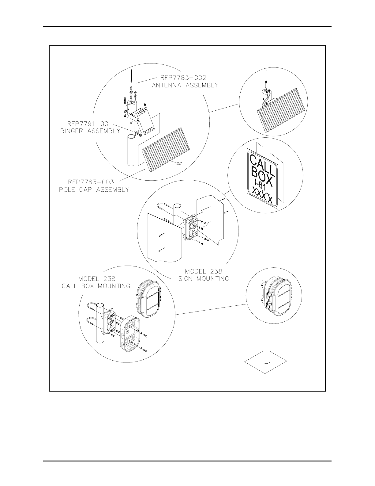
The Model WCB104 Wireless Call Box with
Handset is a highway emergency telephone preprogrammed with telephone numbers for police,
ambulance, and other roadside assistance.
The call box is designed to be mounted to an
existing nominal 4-inch O.D. steel pole using
the Model 238 Pole-Mounting Bracket Kit and
the Model RFP7783-003 Pole Cap Assembly
Kit, which provides weather-resistant cable
entr y and i ncludes a solar panel.
Model RFP7783-001 External Ringer Kit with
Stainless Steel Ringer Bracket and Model
RFP7783-002 Antenna Kit are also required.
AMBULANCE
TOW TRUCK
VOLUME
CA
PLALCTED
POLICE
FIRE
As an opti on, s igns c an be mounted onto th e
pole using an additional Model 238 PoleMounting Bracket Kit.
The call box consists of a 3-section hinge d
aluminum enclosure. It is designed to be
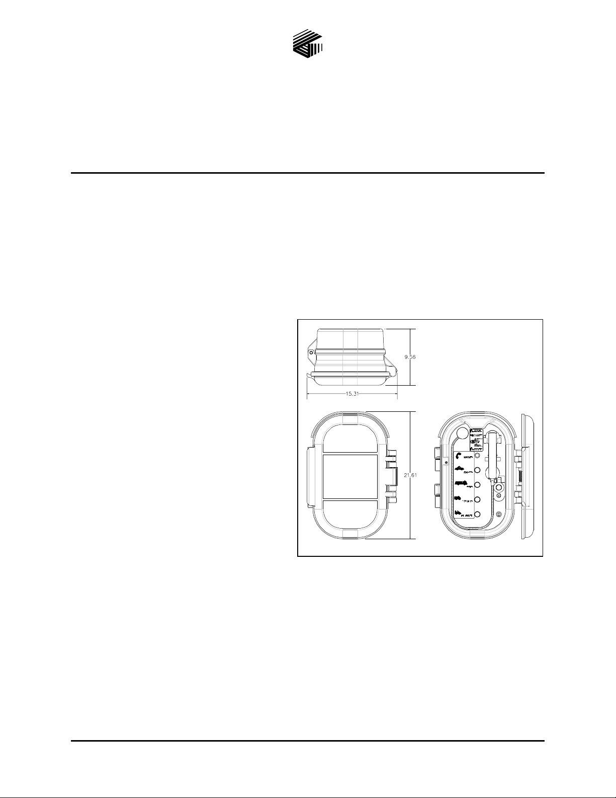
Figure 1. WCB104 Call Box Outline
with Front Panel View
vandal-resistant and meet the requirements of the Americans with Disabilities Act (ADA-compliant).
Refer to Figure 1. The call box auto-dial phone is battery powered with solar panel recharging. The
antenna provides wireless communication access. A pole-mounted external ringer is also available.
The Model 238 Pole-Mounting Bracket Kit is required in order to install the call box on a nominal 4-inch
O.D. metal pole. Refer to GTC Publication 42003-187 for mounting instructions.
The Model RFP7783-003 Pole Cap Assembly Kit is required for installation of the solar panel, cellular
antenna, and external ringer. The solar panel is included with the kit. The antenna and ringer must be
purchased separately. Refer to GTC Publication 42003-188 for complete assembly instructions.
GAI-Tronics Corporation P.O. Box 1060, Readi ng, PA 19607-1060 USA
610-777-1374 800-492-1212 Fax: 610-796-5954
ISIT WWW.GAI-TRONICS.COM FOR PRODUCT LITERATURE AND MANUALS
V
Page 2

Pub. 42004-327A
Model WCB104 Wireless Call Box Installation Gui de Page: 2 of 10
Installation
The 4-inch O.D. pole must be installed in accordance with the applicable state highway regulations for
emergency access equipment. Figure 2 on page 3 shows a pole with the finished installation including the
call box with mounting bracket, the signs with mounting bracket, the pole cap, antenna, and solar panel.
Pole Mounting
Ass e mble t he followi ng requir e d materials and to ols:
• Model 238 Pole-Mounting Bracket Kit
(Quantity of 2)
• Model RFP7791-001 External Ringer Kit with Stainless Steel Ringer Bracket
• Model RFP7783-002 Antenna Kit
• Model RFP7783-003 Pole Cap Assembly Kit
• Identif i c ati on signs a nd mounting hardware, a s appropriate f or loca tion
• Dril l, with 1- inch b it
• Torque wrench
• ¾-inch socket with ratchet
• Crimp tool for TNC coaxial connector
• Wire cutters
• Coaxial cable stripper
Install the Pole- Mounting Bracke t for the Call Box
Mount the required Model 238 Pole-Mounting Bracket for the call box in accordance with the instructions
given in GTC Publication 42003-187, which is included with the kit.
Instal l the Pole- Mountin g Mountin g Bracke t for the Sig ns
Mount the second Model 238 Pole-Mounting Bracket for the identification signs in accordance with GTC
Publication 42003-187, which is included with the kit.
Attach the Comp leted Pole Cap Assemb ly
The Model RFP7783-003 Pole Cap Assembly Kit contains the materials required to install the solar
panel, cellular antenna, and the external ringer onto the pole. The solar panel is included with the pole
cap assembly kit. The antenna and ringer are purchased separately. Assemble the kit and install on the
pole in accordance with GTC Publication 42003-188, which is included with the kit.
\\s_eng\gtc proddoc s \st andard iom s - current release\42004 instr. manuals \ 42004-327a. doc
12/00
Page 3
Pub. 42004-327A
Model WCB104 Wireless Call Box Installation Gui de Page: 3 of 10
Figure 2. Completed I nstallati on with Ca ll Box, Signs, Solar Pane l, Antenna , and Pole Cap
\\s_eng\gtc proddoc s \st andard iom s - current release\42004 instr. manuals \ 42004-327a. doc
12/00
Page 4
Pub. 42004-327A
Model WCB104 Wireless Call Box Installation Gui de Page: 4 of 10
Moun ting the Call Box
1. Prior to installation of call box, complete the mounting bracket installation as outlined in GTC Pub.
42003-187 and the pole cap assembly installation as outlined in GTC Pub. 42003-188.
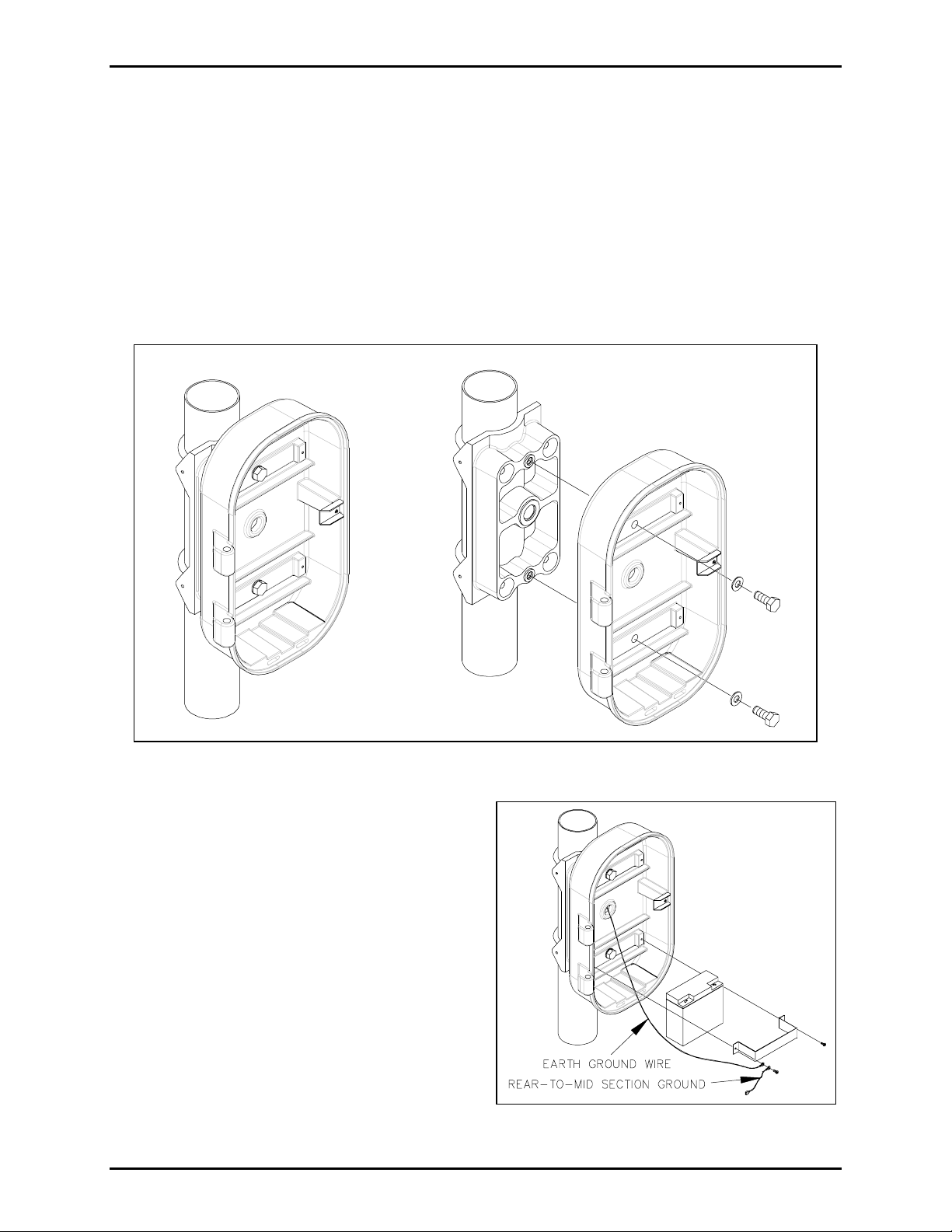
2. Disassemble the call-box assembly by opening the rear section and lifting. To open the rear section,
turn the key and push the button to actuate the lever latch assembly. If necessary, disconnect the
GN/YW ground wire on the left side of the battery bracket. Place the front and middle sections in a
secure area to prevent damage until installation of rear section is complete.
3. Pull the cables and wires through the 1-inch hole drilled previously in the pole and through the
mounting bracket.
4. Pull the cables and wire through the rear section of the call box.
Figure 3. Mounting Call Box to Pole Mounting Bracket
5. Mount the call box rear section using the two
bolts provided to mate the call box to the
mounting bracket holes. Refer to Figure 3 above.
Tighten the bolts to a torque of 20 foot-pounds.
6. Install battery as shown in Figure 4. Install the
earth ground wi re a nd the rear - to-middle grou nd
wire on the left side of the battery bracket.
7. Install the fro nt and c e nter sections of the call
box by lining up the hinge pins while in the open
position and lowering into place.
\\s_eng\gtc proddoc s \st andard iom s - current release\42004 instr. manuals \ 42004-327a. doc
12/00
Figure 4. Battery Installation
Page 5

Pub. 42004-327A
Model WCB104 Wireless Call Box Installation Gui de Page: 5 of 10
Wiring
Refer to Figure 5 below:
Figure 5. View of Call-Box PCBA and Con nector L ocations
1. Terminate the supplied TNC coaxial connector on the RG-58 coaxial cable as outlined in the antenna
installation guide provided with antenna. Plug into the TNC socket connector.
2. Terminate the ringer wiring onto the ringer using 0.25-inch fast-on connectors.
Observe polarity:
• (+) Orange
• (–) Black
Apply protective coating (RTV, or equivalent) to terminals to protect against the environment.
3. Insert a 18011-001 Ferrite Bead over the OR and BK ringer wires. Slide the bead to the point at
which the wires enter the enclosure. Loop the OR and BK wires through the bead 2 times. Terminate
ringer wiring to TB1-1 (-) and TB1-2 (+) on the call box PCBA.
\\s_eng\gtc proddoc s \st andard iom s - current release\42004 instr. manuals \ 42004-327a. doc
12/00
Page 6

Pub. 42004-327A
Model WCB104 Wireless Call Box Installation Gui de Page: 6 of 10
4. Insert a 18011-001 Ferrite Bead over the G and G solar panel integrity loop wires. Slide the bead to
th e point at wh ich the wi res enter th e enclosure. Loop th e G an d G wires through the bead 2 times.
Ter minat e the green i ntegrity loop w i re to c onnec tor J 7-3, 4 of th e controll er boa rd ins ide th e c all
box.
5. Connect the GN/YW ground wire from the middle section to the GN/YW ground wire on the rear
section.
6. Place the temperature sensor against the left side of the battery. Remove the paper backing from the
foam pad. Place the foam pad over the temperature sensor to hold it in place.
7. Verify the correct hardware settings are enabled on the call box PCBA. Refer to the Hardware
Settings Table below.
Hardware Settings Table
Jumper Function Default User
J6 Handset or H/ F Mic Handset
J9 Lamp or LED Lamp LED Lamp
J12 Configuration Enable/Disable Disable
8. Prior to connecting the battery, place the keyswitch in the ACCESS position (CCW) to prevent
unauthorized access call-ins. Install the battery cables as follows:
• RD - battery (+)
• BK - battery (-)
The call box has now been activated. Do not connect if the unit will not be activated.
9. Terminate the solar panel wires to the charge controller terminals inside the call box:
• BK - array (+)
• WH - array (-)
Clamp the split ferrite bead over the solar panel wires and place the bead at the wire entrance to the
enclosure.
10. Ins pect the activat e d L ED on the charge c ontr oller . The ac tiva ted LE D should be OFF.
Warning: If an undercharged battery is installed, the Low Voltage Detection “Activated” LED will
remain ON. The quiescent current draw from the battery will increase by 40 mA. Refer to the
Aut omati c Sequenc ing C harger ASC Ma nual for detail s on disabl ing t his output.
11. The call box does not contain default phone numbers or call-in numbers. If the unit is already been
conf igured, continue with f i nal a ssemb ly. If the uni t has not be e n configured or needs configurat ion
changes, refer to the GTC Wireless Call Box Configuration Application Publication 42004-663L2.
Final Assembly
1. Close the middle section while the front door remains open. Close the lever latch while pushing on
the operator’s front panel and lock using the key. Return the keyswitch to the NORMAL position
(center position).
2. Allow the spring-loaded front door to close.
\\s_eng\gtc proddoc s \st andard iom s - current release\42004 instr. manuals \ 42004-327a. doc
12/00
Page 7

Pub. 42004-327A
Model WCB104 Wireless Call Box Installation Gui de Page: 7 of 10
Operational Check
Outbound Calls
1. Open the front door and verify the illumination LEDs are ON.
2. Remove the handset from the cradle and verify dial tone is present in the receiver.
3. Depress the P
OLICE autodial button .
• Ringing will broadcast in the receiver.
• The C
point, the C
ALL PLACED LED flashes until communication with the network is established. At that
ALL PLACED LED will be lit steadily.
4. Once the Call Center has answered, the ANI and Button ID Number will be transmitted (this will be
audible in the handset receiver).
5. When the C
ALL CONNECTED LED illuminates , communication wit h an operat or will be enabled.
6. Return the handset to the cradle to terminate the call.
7. Perform steps 2 through 6 for autodial buttons F
IRE, AMBULANCE, and TOW TRUCK.
Inbound Calls
1. Place a call t o the Cal l Ce n ter an d reques t a cal l ba ck from t he operat or.
2. The ringer will sound.
3. Remove the handset from the cradle.
4. Communication with an operator will be enabled.
5. Depress t he volume contr o l . The receiver volume increas es with eac h depression. On the 5
depression, the receiver volume returns to the default setting.
6. Return the handset to the cradle to terminate the call.
\\s_eng\gtc proddoc s \st andard iom s - current release\42004 instr. manuals \ 42004-327a. doc
12/00
th
Page 8

Pub. 42004-327A
Model WCB104 Wireless Call Box Installation Gui de Page: 8 of 10
Maintenance
Troubleshooting the Installation
Problem Reason Solution
Solar panel troubles
Cha rger troubles and st atu s
information
Battery troubles
Battery is fully charged, but
phone does not operate.
LED I llumination La mp
does not light.
Refer to Automatic Sequencing Charger ASC
Manual for deta ils.
Refer to Automatic Sequencing Charger ASC
Manual for deta ils.
Refer to Automatic Sequencing Charger ASC
Manual for deta ils.
1. Battery-to-charger
Replace the fuse.
fuse is blown.
2. Call box PCBA
Replace the fuse.
fuse is blown.
1. Pow er fail ur e. Ch eck p ower to the un i t.
2. Supervision Select
Move J9 from LAMP to LED LAMP
jump er J9 ins tall e d
incorrectly.
3. Outer Door Sensor
failure
Check operat ion of the Outer Door Sensor.
The sensor should measure:
• Door closed = 1.0 ohm or less
• Door open = infi nite
Repl ace t he sens or if fail e d.
4. LED lamp failure
5. Other Depress Reset button S2.
No dialtone.
1. Pow er fail ur e Ch eck p ower to the un i t.
2. Configuration
jumper error
3. Hookswitch failure
4. Handset failure Replace handset with a known good unit.
5. Other Depress Reset button S2.
Dialtone, but no ringing. Push button failure
The LED lamp should measure:
Door open – TB1-9 and TB1–10 = 6.7 V dc
Replace LED lamp assembly if failed.
Place Config jumper J12 in Disable position.
Check oper ation of t he Hooksw itch S ensor.
The hookswitch should measure:
• On-Hook = 1.0 ohm or less
• Off-Hook = infinit e
Replace hookswitch if failed.
Check operat ion of the push button. T he p ush
but ton should measure:
• Active = 1.0 ohm or less
• Inactive = infinite
Replace push button if failed.
\\s_eng\gtc proddoc s \st andard iom s - current release\42004 instr. manuals \ 42004-327a. doc
12/00
Page 9

Pub. 42004-327A
Model WCB104 Wireless Call Box Installation Gui de Page: 9 of 10
Problem Reason Solution
No microphone audio.
Ringing, but CALL PLACED
LED does n ot fla sh.
CALL PLACED LED flashes,
but does not turn on
steadily.
CALL CONNECTED LED
doesn’t light whe n operator
answers.
Receiver volume does not
increase.
1. Other Depress Reset button S2.
2. Handset failure Repla ce the handset with a kn own g ood un it.
CALL PLACED LED
failure
During ringing, the CALL PLACED LED should
measure:
TB1-3 and TB1-4 = 1.7 V dc
Replace LED lamp assembly if failed.
Unable to establish
communication with
the cellular network.
1. Place handset back on hook and try to
establish call again.
2. Depress Reset button S2.
3. Check antenna connections.
4. Replace cellular module with a known
good unit.
CALL ANSWERED LED
failure
Once t he operato r s peak s, the CALL
ANSWERED LED should measure:
TB1-5 and TB1-6 = 1.7 V dc
Replace LED lamp assembly if failed.
Pus h button failu re
Check operat ion of the push button. T he p ush
but ton should measure:
Incoming Call = 11.0 V dc or greater during
(2s - ON, 4s – OFF)
Replace push button if failed.
Ringer does not sound. Ringer failure
Solar Pa ne l Inte grity Loop
Inte grity Loop fai lure
Failure reported, but
integrity loop is intact.
Unit does not call-in when
Tilt Sensor failu re
tilted.
Handset Inte grity Loop
Inte grity Loop fai lure
failure reported, but
integrity loop is intact.
Unit does not call-in.
1. Pow er fail ur e Ch eck p ower to the un i t.
2. Call-in failure Depress Call-i n switc h.
3. Other Depress Reset button S2.
Check operat ion of the ringer. The ring er
should measure:
• Active = 1.0 ohm or less
• Inactive = infinite
Replace ringer if failed.
Check operat ion co ntinuit y of th e loop. The
loop should measure 1 .0 ohm or less.
Re-terminate connector if necessary.
Check oper ation of t he tilt sens or. T he sensor
should measure:
• Inactive = 1.0 ohm or less
• Active = infinite
Replace sensor if failed.
Check operat ion co ntinuit y of th e loop. The
loop should measure 1 .0 ohm or less.
Re-terminate connector if necessary.
\\s_eng\gtc proddoc s \st andard iom s - current release\42004 instr. manuals \ 42004-327a. doc
12/00
Page 10

Pub. 42004-327A
Model WCB104 Wireless Call Box Installation Gui de Page: 10 of 10
Specification s
Enclosure material and coating......................................... Cast aluminum with yellow polyurethane finish
U-bolt material...............................................................................................................304 stainless steel
Dimensions
Call Box, overall .............................................................................................21.61 × 15.31 × 9.56 inches
Weight (without battery)..................................................................................................................46 lbs.
\\s_eng\gtc proddoc s \st andard iom s - current release\42004 instr. manuals \ 42004-327a. doc
12/00
Page 11

Warranty
Equipment. GAI-Tronics warrants for a period of one (1) year from the date of shipment, that any
GAI-Tronics equipment supplied hereunder shall be free of defects in material and workmanship, shall
comply with the then-current product specifications and product literature, and if applicable, shall be fit
for the purpose specified in the agreed-upon quotation or proposal document. If (a) Seller’s goods prove
to be defective in workmanship and/or material under normal and proper usage, or unfit for the purpose
specified and agreed upon, and (b) Buyer’s claim is made within the warranty period set forth above,
Buyer may return such goods to GAI-Tronics’ nearest depot repair facility, freight prepaid, at which time
they will be repaired or replaced, at Seller’s option, without charge to Buyer. Repair or replacement shall
be Buyer’s sole and exclusive remedy. The warranty period on any repaired or replacement equipment
shall be the greater of the ninety (90) day repair warranty or one (1) year from the date the original
equipment was shipped. In no event shall GAI-Tronics warranty obligations with respect to equipment
exceed 100% of the total cost of the equipment supplied hereunder. Buyer may also be entitled to the
manufacturer’s warranty on any third-party goods supplied by GAI-Tronics hereunder. The applicability
of any such third-party warranty will be determined by GAI-Tronics.
Services. Any services GAI-Tronics provides hereunder, whether directly or through subcontractors,
shall be performed in accordance with the standard of care with which such services are normally
provided in the industry. If the services fail to meet the applicable industry standard, GAI-Tronics will
re-perform such services at no cost to buyer to correct said deficiency to Company's satisfaction provided
any and all issues are identified prior to the demobilization of the Contractor’s personnel from the work
site. Re-performance of services shall be Buyer’s sole and exclusive remedy, and in no event shall GAITronics warranty obligations with respect to services exceed 100% of the total cost of the services
provided hereunder.
Warranty Periods. Every claim by Buyer alleging a defect in the goods and/or services provided
hereunder shall be deemed waived unless such claim is made in writing within the applicable warranty
periods as set forth above. Provided, however, that if the defect complained of is latent and not
discoverable within the above warranty periods, every claim arising on account of such latent defect shall
be deemed waived unless it is made in writing within a reasonable time after such latent defect is or
should have been discovered by Buyer.
Limitations / Exclusions. The warranties herein shall not apply to, and GAI-Tronics shall not be
responsible for, any damage to the goods or failure of the services supplied hereunder, to the extent
caused by Buyer’s neglect, failure to follow operational and maintenance procedures provided with the
equipment, or the use of technicians not specifically authorized by GAI-Tronics to maintain or service the
equipment. THE WARRANTIES AND REMEDIES CONTAINED HEREIN ARE IN LIEU OF AND
EXCLUDE ALL OTHER WARRANTIES AND REMEDIES, WHETHER EXPRESS OR IMPLIED BY
OPERATION OF LAW OR OTHERWISE, INCLUDING ANY WARRANTIES OF
MERCHANTABILITY OR FITNESS FOR A PARTICULAR PURPOSE.
Return Policy
If the equipment requires service, contact your Regional Service Center for a return authorization number
(RA#). Equipment should be shipped prepaid to GAI-Tronics with a return authorization number and a
purchase order number. If the equipment is under warranty, repairs or a replacement will be made in
accordance with the warranty policy set forth above. Please include a written explanation of all defects to
assist our technicians in their troubleshooting efforts.
Call 800-492-1212 (inside the USA) or 610-777-1374 (outside the USA) for help identifying the
Regional Service Center closest to you.
(Rev. 10/06)
 Loading...