

Page 1

3XED
GAI-TRONICS
A division of Hubbell Ltd
VoIP Telephones
Configuration Guide:
Firmware version 3
(The previous versions of this manual, for firmware versions 1 & 2, remain available)
Document Ref: 502-20-0119-001 Issue 3. Apr 2012. CN33927-001
Page 2

GAI-TRONICS
3XED
VoIP Telephones
Configuration Guide
Firmware version 3
CONFIDENTIAL
The contents of this publication are confidential, are the property of GAI-Tronics, and may not
be reproduced, wholly or in part, without their written permission.
TRADEMARKS and LICENCES
Windows is a trademark of Microsoft Corporation, registered in the United States and other
countries.
All other product and brand names are trademarks of their respective owners.
Software licences and notices are available on the GAI-Tronics website at www.gai-
tronics.co.uk/voipsupport.htm
POLICY
The policy of GAI-Tronics is one of continual development and improvement of products and
we reserve the right therefore to alter specifications without notice.
GAI-Tronics
Brunel Drive
Stretton Park
BURTON-UPON-TRENT
Staffordshire
England
DE13 0BZ
Tel.: +44 (0)1283 500500
Fax.: +44 (0)1283 500400
www.gai-tronics.co.uk
VoIP Telephone Configuration Guide Page 2 of 88
Page 3

GAI-TRONICS
3XED
Contents
1.Introduction ......................................................................................................................... 5
2.What's new ? ...................................................................................................................... 5
2.1New in Version 3 ........................................................................................................ 5
2.2New in Version 2 ........................................................................................................ 6
3.How the product is intended to work .................................................................................. 6
3.1Operating Sequence. ................................................................................................. 7
3.2Dictionary of terms ..................................................................................................... 7
4.Setting up and Configuring the telephones. ....................................................................... 9
4.1Quick Start ................................................................................................................. 9
4.2Frequently Asked Questions (FAQs) ......................................................................... 9
4.2.1What network facilities do I need to provide? ...................................................... 10
4.2.2How do I set up dialling and memory lists? ......................................................... 10
4.2.3Can I set the phone to make calls without a proxy (ie peer-to-peer)? ................. 11
4.2.4How do I set up Real-time alarm reporting via email or syslog? ......................... 11
4.2.5How can I set up an external beacon to flash when the phone is ringing? ......... 12
4.2.6How do I set up a door-entry system? ................................................................. 13
4.2.7How can I use the phone to make paging or PA announcements? .................... 14
4.2.8What additional features are available with CMA? .............................................. 14
5.Web pages in detail .......................................................................................................... 14
5.1Login ........................................................................................................................ 15
5.2Home Page .............................................................................................................. 16
5.3IP settings ................................................................................................................ 17
5.3.1Note about Syslog: .............................................................................................. 18
5.4SIP settings .............................................................................................................. 19
5.4.1SIP Info sub-pages: ............................................................................................. 21
5.5Unit settings ............................................................................................................. 22
5.5.1Audio Path Test ................................................................................................... 24
5.6Access settings ........................................................................................................ 25
5.7Serial settings .......................................................................................................... 26
5.8Email settings .......................................................................................................... 27
5.9Clock settings .......................................................................................................... 28
5.10Dialling & Memories ................................................................................................. 29
5.10.1Memories sub-page ......................................................................................... 30
5.10.2Memory Lists sub-page. .................................................................................. 31
5.10.3Basic Info sub-page. ........................................................................................ 32
5.11Key mapping ............................................................................................................ 33
5.11.1Activating relays using DTMF codes ............................................................... 35
5.12Current status .......................................................................................................... 36
5.13Audio settings .......................................................................................................... 37
5.14Alarm settings .......................................................................................................... 39
5.15Tone settings ........................................................................................................... 42
5.15.1Suggested Tone Settings for Various Countries: ............................................ 44
5.16LED settings ............................................................................................................ 45
5.17Logic settings ........................................................................................................... 48
5.18Multicast settings ..................................................................................................... 50
6.Configuration File update ................................................................................................. 53
6.1Configuration File Syntax......................................................................................... 55
6.2Configuration File Commands ................................................................................. 56
7.Time Zone Table .............................................................................................................. 66
8.Example Configuration File .............................................................................................. 68
9.Command Line Interface .................................................................................................. 72
9.1CLI Syntax ............................................................................................................... 73
9.2ACCESS Module Command Line Syntax ................................................................ 74
9.3ALARMS Module Command Line Syntax ................................................................ 75
9.4KEY Module Command Line Syntax ....................................................................... 76
9.5LED Module Command Line Syntax ....................................................................... 76
9.6DIALPLAN Module Command Line Syntax ............................................................. 77
9.8CLOCK Module Command Line Syntax .................................................................. 78
9.9AUDIO Module Command Line Syntax ................................................................... 79
VoIP Telephone Configuration Guide Page 3 of 88
Page 4

GAI-TRONICS
3XED
9.10TONES Module Command Line .............................................................................. 79
9.11IP Module Command Line Syntax ........................................................................... 80
9.12LOCAL Module Command Line Syntax ................................................................... 80
9.13LOGIC Module Command Line Syntax ................................................................... 81
9.14SIP Module Command Line Syntax ......................................................................... 82
9.15SMTP Module Command Line Syntax .................................................................... 83
9.16Status Module Command Line Syntax .................................................................... 83
9.17UNIT Module Command Line Syntax ...................................................................... 84
9.18Multicast Module Command Line Syntax ................................................................ 85
10.Reset to Defaults ......................................................................................................... 86
11.Troubleshooting ........................................................................................................... 87
11.1Is the unit powered up? ........................................................................................... 87
11.2I can't access the web pages ................................................................................... 87
11.3I can't make calls ..................................................................................................... 87
11.4Calls connect but there is no speech (or sound is garbled) .................................... 88
12.Licensing Notices ......................................................................................................... 88
VoIP Telephone Configuration Guide Page 4 of 88
Page 5

GAI-TRONICS
3XED
1. Introduction
This guide provides information on the operation and configuration of GAI-Tronics' range of
rugged VoIP telephones with firmware version 3, released in January 2012.
There are significant changes to some of the web pages and commands from those in
previous versions. Issue 1 and issue 2 of this manual will remain available on the GAITronics UK website (www.gai-tronics.co.uk/voipsupport.htm
versions.
The firmware version of each unit is displayed at the bottom of its home web page, and as
part of the welcome message following login via a Telnet or serial connection.
In each case the firmware version is a series of 3 numbers separated by dots (periods). The
main firmware version is the first number. For example:
Upgrading to the latest version is possible in most circumstances, but please note that certain
new features may not be enabled on upgraded phones - contact GAI-Tronics for details.
GAI-Tronics VoIP telephones are available in a variety of model styles, including handset and
hands-free models, but the programming and configuration methods are common to all.
Please note that the features may depend on the model type, and that therefore this guide
may describe features not available on the particular model being configured.
Features of the GAI-Tronics range of VoIP telephones include:
• SIP compatible (RFC3261) only
• Registration with multiple SIP proxies (new in v2)
• Configurable via web pages, serial link or downloading a configuration file
• Outgoing cascading call lists
• Real-time alarm reporting via email or Syslog
• 4 auxiliary inputs, 2 volt-free contact outputs (revised in v2)
• Remote operation of contacts ("door opening" function)
• 3 “autoanswer” modes, including paging mode (revised in v2)
• Compatible with GAI-Tronics' Call Management Application (CMA)
This guide does not include information on:
• Installation, cabling and connections (see guide 502-20-0115-001 for non ATEX
phones and 502-20-0133-001 for Auteldac4 VoIP)
• Setting up, configuring and operating a network for VoIP. Please ensure that the
network is configured to allow VoIP communications (using the SIP protocol) between
the desired locations before attempting to configure GAI-Tronics telephones.
) as a reference for earlier
1.2.13 indicates firmware version 1
2.1.6 indicates firmware version 2.
3.0.0 indicates firmware version 3.
2. What's new ?
2.1 New in Version 3
Version 3 added the following features from version 2:
Acoustic Path Testing (APT)
APT allows remote testing of handsets, microphones and speakers. APT can be used to
verify that a phone is functioning acoustically. The test can be run on demand or on a
scheduled basis, reporting its results via Syslog and / or email. See section 5.5.1.
Multicast
(Only applicable to hands-free products). Multicast allows a single audio stream to be
received by multiple endpoints simultaneously, to achieve multi-point paging or Public
Address functionality over IP. (Requires a multicast compliant SIP server). 8 definable
multicast address ranges, with individual priority levels, for zoning. Assignable relay outputs
and splash tones. See section 5.18.
VoIP Telephone Configuration Guide Page 5 of 88
Page 6

GAI-TRONICS
Reset to factory defaults
The unit can be restored to factory defaults by pressing an internal reset button on the PCB.
This can be used to recover a phone where the user name or password have been lost. See
section 10.
Relay operation from DTMF tones
For door opening purposes, output relays can now be triggered by the receipt of a
programmable DTMF tone sequence. This means that a phone's relays could potentially be
triggered from any phone on the system. See section 5.11.1.
Default autoanswer mode
The unit can now be set to automatically answer an incoming call, with a choice of 3 different
autoanswer modes to suit applications such as paging and intercom. See section 5.5.
3XED
2.2 New in Version 2
Version 2 firmware added the following features from version 1:
Multiple SIP proxies
The unit can now hold up to 4 alternate addresses for the SIP proxy and registrar with a
prioritised failover sequence between them. This means that if it fails to register with the first
server it will attempt to do so with the next and so on.
The unit can be set to automatically refresh its registration at a predetermined interval to
ensure that registration is maintained at all times (or if not raise an alarm).
This provides a high degree of resilience across the network and reduces the possibility of a
single point of failure jeopardising the operation of the whole system.
Additional functions for Relay outputs and LEDs
In addition to the functions in version 1, the unit can now trigger its output relays and / or
LEDs on:
• PAGE (activated by PAGEMODE, see section 5.5). For example a relay could be used to
activate a public address amplifier, allowing the unit to be used as a mini PA.
• EMERGENCY (if an outgoing call is designated as an emergency call), where for
example a relay could be used to activate an emergency beacon, and
• REGISTERED, where for example an LED could indicate that the unit is available for use
(i.e. it can make a call).
Additional LED drive
Version 2 allows 3 programmable LEDs instead of 2. Note that the number of LEDs fitted
varies with model type. Some standard models have no LEDs fitted.
Page Mode
Auto-answer mode 3 is now explicitly referred to as PAGE MODE to highlight its potential use
as a PA or paging system. Functionally it is unchanged, except for the LED and relay triggers
described above.
3. How the product is intended to work
The VoIP telephone has been designed to mimic the behaviour of a traditional, analogue
telephone, specifically based on the GAI-Tronics range of rugged telephones, to give
continuity where VoIP and analogue units are used in similar situations.
Accordingly, traditional telephone terminology is used throughout the manuals and
documentation, and many of the features are designed to mimic analogue telephone
behaviour.
A major difference between analogue telephones and VoIP is that, with analogue units, most
signalling and tones such as ringing, dial tone, busy tone etc., are provided by a telephone
exchange (PABX), whereas the VoIP unit must generate these itself. The telephone provides
features to change the various tones to emulate those of different countries or PABXs, to give
familiar operation in its intended location.
VoIP Telephone Configuration Guide Page 6 of 88
Page 7

GAI-TRONICS
3.1 Operating Sequence.
Typical sequences of events for various model types are explained below:
Handset models (Titan, Commander)
Placing a call
• Lift handset (off hook)
• Dial tone in receiver
• Dial number - confidence tones in receiver
• Call progress tone in receiver (e.g. ring tone)
• Call is answered by remote party
• Normal voice call
• Replace handset (on hook)
• Call terminates.
Receiving a call
• Telephone rings
• Lift handset (off hook)
• Normal voice call
• Replace handset (on hook)
• Call terminates.
Hands-free models (VR, Help Point)
Placing a call
• Press button
• Dialling confidence tones heard from speaker (wake and dial)
• Call progress tone heard from speaker (e.g. ring tone)
• Call is answered by remote party
• Normal voice call
• Call terminates. (On hook)
Receiving a call
• Ringing heard from speaker
• Press any button to answer call (off hook)
• Normal voice call
• Call terminates. (On hook)
3XED
3.2 Dictionary of terms
Busy tone
A tone played to the user to indicate that a call has failed because the called party is engaged
Call progress tone
One of a number of different tones played to the user to indicate the status of a call. Dial
tone, busy tone and NU tone are all examples of call progress tones.
Confidence tones
Tones played to the user to indicate that dialling is in progress, by imitating DTMF tones used
by analog telephones.
Dial tone
A tone played to the user to indicate that the telephone is ready to dial – ie it is off hook and
waiting for a button to be pressed to initiate a call.
Dialling
Used to describe the process of initiating a call, usually by pressing a memory button or a
series of digit buttons.
DTMF
Standing for “dual tone multi-frequency”, the dialling digit tones produced by a touch-tone
phone. Commonly used for signalling in analogue systems.
VoIP Telephone Configuration Guide Page 7 of 88
Page 8

GAI-TRONICS
3XED
Handset phone
Used to denote a telephone from the GAI-Tronics Titan or Commander product ranges, with a
separate handset attached to the main telephone body by a heavy duty flexible cord. No
separate loudspeaker is fitted to these models.
Hands-Free phone
Used to denote a telephone from the GAI-Tronics Help Point or Vandal Resistant product
ranges, with a microphone and speaker integrated into a flat panel. No corded handset is
fitted to these models.
LNR
Standing for “last number redial”, this is a button provided on some models of GAI-Tronics
phone to redial the last manually dialled number.
Memory dial number
On an analogue or cellular phone, memory numbers are pre-stored digit sequences used to
start calls. With VoIP these can also be URI’s rather than numbers, but are still referred to in
the same way.
Mute
A function to temporarily mute the microphone so that the remote party cannot hear. On GAITronics telephones this function is provided by the "S" button.
NU tone
Number unobtainable tone – used to indicate that a call cannot connect due to the end point
not being recognised.
Off hook
Used to denote the state of a telephone during an active call, or when a call has been
initiated. For a handset phone, off hook usually means that the handset is lifted.
On hook
Used to denote a telephone in the idle state – no call started or answered. A telephone is still
on hook when it is ringing on an incoming call. For a handset phone, on hook usually means
the handset is not lifted. If a call is terminated whilst the handset is still lifted (for example by
the CALL LIMIT timer), the telephone is placed into the on hook state. For a hands-free
phone, on hook means that no ON or WAKE & DIAL button has been pressed following a
terminated call or reset.
Recall
On analogue phones, the Recall button is used to activate exchange signal, usually to
transfer a call. The GAI-Tronics VoIP telephone does not have a recall facility, but the “R”
button (where fitted) can be used to activate an output on a remote phone, for example as a
door release.
Register Fail tone
A tone played to the user initiating a call to indicate that the telephone is not currently
registered with a registrar, meaning that a call cannot be made.
Ring tone
A tone played to the user initiating a call to indicate that the call has been placed but not yet
answered. This usually signifies that the remote end is ringing.
Ringing
A loud alert tone made by the telephone indicating that an incoming call is ready to be
answered.
Secrecy (mute)
A function to temporarily mute the microphone so that the remote party cannot hear. On GAITronics telephones this function is provided by the "S" button.
VoIP Telephone Configuration Guide Page 8 of 88
Page 9

GAI-TRONICS
3XED
Sidetone
On handset phones, part of the microphone signal is fed to the earpiece so that the user can
hear his or her own voice during the call. This makes it a more natural experience, and has
been a feature of analogue telephones since their invention. Not used on hands-free phones.
4. Setting up and Configuring the telephones.
Each telephone must be configured for use on the intended network. Most models have
memory-dial locations, which will need to be set up. The telephone also has a range of
customisable features. All of these can be set up using one of 4 different methods:
• Web pages (the simplest and quickest method for configuring an individual phone)
• Downloading configuration files (the most efficient method for multiple updates)
• Command-line commands via direct serial link
• Command-line commands via Telnet session
Note:
All the above access methods require you to know the unit's username and password.
All methods, except direct serial link, also require you to know the unit's IP address.
Please ensure these details are recorded securely once set or changed.
All of the telephone's features can be configured using any of the above methods, but the
most complete description of features is contained in the web page section (Section 5).
4.1 Quick Start
The factory defaults will generally be sufficient in most cases, but the following steps must be
taken as a minimum:
• Provide an Ethernet connection and power (either 24-48Vdc or PoE)
• Using a web browser, browse to the default IP address 192.168.1.2
• Enter the user name and password (Defaults: user & password)
• Set an IP address and net mask (or set DHCP) on the IP page
• From the SIP settings page, select the SIP1 Info sub-page, check that ENDPOINT is
ENABLED
• On the SIP1 Info sub-page, give the phone a LOCALID (usually its extension number)
• On the SIP1 Info sub-page, set DOMAIN, PROXY and REGISTRAR all to the
address of the SIP server. If registrar authentication is in use, also set a user name
and password.
• Program any dial memories using the Dialling & Memories pages
With these basic steps the telephone will be able to make and receive calls in most cases.
Check the Current Status page to help diagnose problems - this will show whether or not the
phone is registered and what is happening during calls (refresh the page to see changes).
NOTE:
Make sure each unit is given at least a basic configuration before installing it. All units have
identical settings as factory defaults, so each one must be individually configured to give it a
unique identity on the network. This may be difficult to do after the units are installed.
1,2
4.2 Frequently Asked Questions (FAQs)
Note: a more up-to date list of questions and answers may be available on the GAI-Tronics
website. See www.gai-tronics.co.uk/voipsupport.htm for more details.
(DUO\PRGHOVZLOORQO\DFFHSW9GFDVDQH[WHUQDOSRZHUVXSSO\ODWHUPRGHOVZLOODFFHSW
9GF8QLWVDUHPDUNHGDFFRUGLQJO\QH[WWRWKHSRZHUWHUPLQDOVVHHLQVWDOODWLRQJXLGH
RUIRU$XWHOGDF9R,3IRUGHWDLOV
)RU$XWHOGDF9R,33R(FDQRQO\EHVXSSOLHGRQWKHVSDUHSDLUDIDOWHUQDWLYH%QRW
WKHGDWDSDLUV6HHLQVWDOODWLRQJXLGHIRUGHWDLOV
VoIP Telephone Configuration Guide Page 9 of 88
Page 10

GAI-TRONICS
3XED
4.2.1 What network facilities do I need to provide?
This may vary widely depending on how your network is constructed and what else it is
carrying, but as a general guide you will probably need:
• A SIP proxy server (to route calls)
• A SIP registrar server (frequently combined with the proxy server) to resolve URIs to
IP addresses
• A TFTP server (for downloading configuration files).
• A TCP Syslog server (for reporting alarms and external inputs)
• An SMTP server (for reporting via email)
• An STNP server (to synchronise the internal clock)
Dedicated systems, such as Gatekeepers, VoIP-enabled PABXs or soft PABXs may also
provide these functions. Bear in mind that GAI-Tronics telephones only support Session
Initiation Protocol (SIP) to RFC3261, as opposed to H.323 or SCCP VoIP protocols for
example.
Note that the performance of VoIP telephones depends on the provision of sufficient
bandwidth and prioritisation on the network to give the quality of service required.
4.2.2 How do I set up dialling and memory lists?
Let's assume you have a telephone with 2 buttons: memory 1 for information, memory 2 for
emergency. You want the emergency button to call "888" only. You want the information
button to call the information desk, or if that is busy the security office, or failing that the
administration centre on 223344.
First set up the 4 possible user agents (end points) as memories on the memories page (it
doesn't matter which end point is in which memory):
Note that comfort strings have been set to give the user confidence that "dialling" is taking
place when the button is pressed.
Then set up 2 memory lists, one for each button:
VoIP Telephone Configuration Guide Page 10 of 88
Page 11

GAI-TRONICS
3XED
Memory list 1 relates to memory button 1, and will dial memories 2, 3 and 4 in cascade.
Memory list 2 is for memory button 2, and will dial memory 1 only.
Note that, in this case, WAKEANDDIAL is set for both - the normal case for help point and
hands-free telephones.
Refer to the Dialling & Memories pages in section 5.10 for more details.
4.2.3 Can I set the phone to make calls without a proxy (ie peer-topeer)?
There are two ways of setting the phone to make peer to peer calls.
The first is where there is no proxy server on the system at all. In this case:
1. Set the ENDPOINT field on SIP 1 Info page to ENABLED, but make sure DOMAIN,
PROXY and REGISTRAR are blank. Set ENDPOINT on SIP info 2, 3 and 4 to
DISABLED.
2. Make each entry on the Memories page the address of an endpoint or phone, in the
form 1@192.168.1.2. Note that the number before the "@" symbol is not normally
significant
address of the end point.
3. Note that peer-to-peer calls can only be made by using a memory - not by manually
dialling from a numeric keypad. All phones have at least one memory list (the
OFFHOOK list). Refer to section 5.10 for details on setting up memories.
The second way is where one or more proxy servers are in use, but you want to be able to
make a peer-to-peer call if no proxy is available. This is referred to as "failover to peer-topeer". In this case:
1. Set the proxy address on one of the 4 SIP info pages (usually the one with the lowest
priority) to be the IP address of an endpoint, in the form 192.168.1.2
REGISTRAR address to be blank.
2. If all attempts to make calls to higher priority proxies fail, the phone will attempt to
place a call to this IP address as a peer-to-peer entity, regardless of what number is
dialled or what entry is selected from a memory list.
NOTE: you cannot make a peer-to-peer call by entering an IP address on a numeric
keypad - peer-to-peer calls can only be made using a memory dial.
3
- there just needs to be a number, followed by "@", followed by the IP
4
, but set the
4.2.4 How do I set up Real-time alarm reporting via email or syslog?
To do this you will need to set up email and/or syslog facilities within the phone, then set up
the alarm itself, using the following 3 web pages:
• Refer to the Email page to enter the required SMTP server settings for email.
• Refer to the IP settings page to set up Syslog server settings.
• Refer to the Alarms page to set which alarm events will report.
In the example shown below, a syslog message will be generated if the telephone has a cold
reset (ie recovers from a power failure) or has an integrity loop fault (ie the handset has been
detached). In addition, it will send an email to the security office if the handset is detached.
6RPH6,3SKRQHVPD\UHTXLUHWKLVWREHWKHLUSKRQHQXPEHU
1RWHWKLVFRXOGDOVREHD)4'1IXOO\TXDOLILHGGRPDLQQDPHLIWKHUHLVD'16DYDLODEOHRQ
WKHQHWZRUN
VoIP Telephone Configuration Guide Page 11 of 88
Page 12

GAI-TRONICS
3XED
4.2.5 How can I set up an external beacon to flash when the phone is ringing?
Traditional telephone beacons and sounders, with ring detectors, will not work on VoIP
because there is no ring signal. You will therefore need a powered beacon or sounder
instead, and use the telephone's volt-free contacts to activate it. These beacons or sounders
must be provided with a separate power supply - they cannot be powered from the telephone.
Having connected an external device to an output (say Output 1), the next step is to set the
output to activate it when required.
Enter the keyword "RING" for the relevant output. The example above shows the output set
with a cadence of 10:0, meaning continuously on. This would be suitable for a beacon,
because beacons usually flash (once per second) when permanently energised. It might not
suit a sounder, however, because it would emit a continuous tone, which might not be
recognisable as a phone ringing. For a sounder on its own, the keyword "RINGCADENCE" is
a better option, causing the sounder to be energised in time with the normal phone ringer.
For a beacon and sounder together, it is often best to use a separate output for each as
shown:
VoIP Telephone Configuration Guide Page 12 of 88
Page 13

GAI-TRONICS
3XED
In this example, Output 1 is set to activate a flashing beacon, whilst Output 2 is set to activate
a sounder in sync with the cadence of the ring signal (set on the Tone settings page). In both
cases the outputs are energised when the phone is ringing with an incoming call, and deenergised when the call is answered or disconnected.
Refer to the Logic Settings page (section 5.17) and Tone settings page (section 5.15) for
more details.
4.2.6 How do I set up a door-entry system?
A common application is to have a single button hands-free telephone mounted outside a
door, and a 15 button Commander model at a remote security point. Visitors arriving at the
door use the hands-free unit to call the security point. A security guard answering the call can
release the door lock by pressing the "R" button on the Commander unit.
To achieve this, connect one of the volt-free outputs on the hands-free telephone (say output
1) to the electronic door release mechanism. Using the Logic settings page, set this output to
PULSE:
Note that the TIMER is set to 3, meaning that the output will remain active for 3 seconds after
being activated.
To activate this output from the security office, set the RECALL setting on the Key mapping
page of the Commander unit to the IP address of the hands-free unit. So, for example, if the
IP address of the hands-free were 192.168.9.2, the setting would be:
VoIP Telephone Configuration Guide Page 13 of 88
Page 14

GAI-TRONICS
3XED
Refer to the Logic settings page (section 5.17) and the Key mapping page (section 5.11) for
more details.
4.2.7 How can I use the phone to make paging or PA announcements?
If you are using GAI-Tronics CMA, simply set the PAGEMODE field (on the UNIT page) to
"aa3". CMA has a page button that will place a call to the unit in page mode, i.e. an
announcement tone will be heard from the unit, following which the CMA operator will be able
to make a page through the unit's speaker (see section 5.5).
It may be possible to activate this feature from systems other than CMA - contact GAI-Tronics
for details.
Note page mode is usually implemented using handsfree models (VR and Help Point for
example) but it may also be possible with other models, depending on application. The
integral relays can also be set to activate during a page, and this feature could be used to
trigger an external public address amplifier. Contact GAI-Tronics for details.
4.2.8 What additional features are available with CMA?
GAI-Tronics CMA is a security call centre application for Windows XP™ designed for use with
GAI-Tronics analogue and VoIP telephones, providing powerful features such as:
• Automatic call answering
• Text-to-speech auto announcements
• Location ID linked to a user-definable mapping application
• Call recording and incident logging
• Call queueing
One of the system's most important functions is to give callers the reassurance that their call
is being dealt with and that their location is known.
The ANI field on the UNIT page is used as an identifying token to CMA. Using this the
telephone can automatically announce location information (using text-to-speech) to the user
and the call centre operator when a call is made. It is also used to locate the phone on a map
to help the operator identify its location and give assistance to the caller.
CMA can also activate 3 special auto-answer modes on hands-free VoIP telephones if
required by using codes also entered on the UNIT page:
Stealth mode, where the operator can listen discreetly to the telephone (the ANSMODE1 field
should be set to "aa1").
Intercom mode, where the operator can make a call to a telephone and start two-way voice
communication immediately, without the user having to answer (the ANSMODE2 field should
be set to "aa2").
Page mode, where the operator can make an announcement directly to the telephone, but not
listen (the PAGEMODE field should be set to "aa3").
5. Web pages in detail
The following sections describe the embedded web pages in detail.
Once past the login screen, all the pages have a similar layout.
VoIP Telephone Configuration Guide Page 14 of 88
Page 15
GAI-TRONICS
Edit button
3XED
Module
name
Navigation
pane
The left hand navigation pane gives direct access to each of the 16 main pages, grouped by
functional headings of Network, Phone functions and Signals & Audio, plus the home page.
Most pages have an "Edit" button that allows the changing of parameters.
Some pages have entry dialog boxes that accept certain predefined values. These values
are listed in the sections below.
Some pages have links to related sub pages.
Each page displays its module name near the top for ease of navigation.
Note that these pages have been developed and tested on Microsoft Internet Explorer (v6).
Screen layout may appear differently using other browsers.
5.1 Login
To access the web pages, navigate to the unit's IP address using a web browser such as
Internet Explorer.
The factory default setting is for static IP addressing, with an address of:
Note that the unit's default subnet mask is 255.255.0.0.
The Phone will request a user name and password as shown.
Links to subpages
Page values
192.168.1.2
VoIP Telephone Configuration Guide Page 15 of 88
Page 16

GAI-TRONICS
The default user name and password are
user
password
(lower case)
The user name and password can be changed using the Access Settings page.
On accepting the username and password, the phone's home page is displayed.
3XED
5.2 Home Page
No settings can be changed directly from the home page.
The Web support page link defaults to http://www.gai-tronics.co.uk/voipsupport.htm, but can
be changed on the Unit Settings page (section 5.5).
VoIP Telephone Configuration Guide Page 16 of 88
Page 17

GAI-TRONICS
At the bottom of the home page (you may need to scroll down, depending on screen
resolution) there is a list of information about the phone including serial numbers of the unit
and its PCBs, software versions and MAC ID.
3XED
5.3 IP settings
The IP settings page is used to display or change various settings for connection to the IP
network.
DHCP: Enables or disables the use of DHCP for the assignment of IP parameters. If this
value is set to OFF the telephone will use the Static IP values. (Values available: ON or OFF,
default value is OFF)
ADDRESS: Sets the static IP Address of the unit. (Default value is 192.168.1.2) Do not enter
a value here if DHCP is set to ON.
MASK: Sets the static sub-net mask. (Default value is 255.255.0.0) Do not enter a value here
if DHCP is set to ON.
GATEWAY: Sets the static default gateway address (Default value is 0.0.0.0)
DNS1: Sets the IP address of the primary static DNS server. If DHCP is enabled then this
DNS server will not be used. (Default value is 0.0.0.0 )
DNS2: Sets the IP address of the secondary static DNS server for redundancy. If DHCP is
enabled then this DNS server will not be used. (Default value is 0.0.0.0 )
LOCALDOMAIN: Sets the domain name of the telephone on the network, as used by DNS.
May be assigned by DHCP.
WEB: Enables or disables access to the web server (Values available: ON or OFF, default
value is ON)
WEBPORT: Sets the TCP port through which the Telephone Web server can be accessed
(Default Value is 80)
TELNET: Enables or disables access to the telnet server (Values available: ON or OFF,
default value is ON)
TELNETPORT: Sets the TCP port through which the Telephones telnet server can be
accessed (Default Value is 23)
SYSLOG: Sets the destination address for syslog server messages. (Valid values: IP
address or FQDN. Default value: blank)
SYSLOGPORT: Sets the port number to be used for syslog messages. The default value is
514
VoIP Telephone Configuration Guide Page 17 of 88
Page 18

GAI-TRONICS
3XED
SYSLOG2: Sets the destination address for a second syslog server for redundancy. (Valid
values: IP address or FQDN. Default value: blank)
SYSLOGPORT2: Sets the port number to be used for syslog messages (second syslog
server). The default value is 514
SYSLOGFACILITY: Sets the SYSLOG message facility level, as per RFC3164. (Default
value: 14)
SYSLOGSEVERITY: Sets the SYSLOG message severity level, as per RFC3164. (Default
value: 5)
STUN: Sets the IP address or URL for the STUN server that will be used to resolve STUN
requests. Leaving this field blank will disable the STUN facility. (Default value: blank)
At the bottom of the IP settings page are 2 action buttons, each with an entry box. The entry
boxes will accept either an IP address or FQDN. These buttons provide useful diagnostic
functions:
PING: Sends an ICMP ping to the entered address, providing a results page.
TRACEROUTE: Executes a series of PING messages with varying HOP numbers in order to
determine the routing used to reach the destination address. A results page is displayed.
5.3.1 Note about Syslog:
GAI-Tronics VoIP products send Syslog messages using TCP (as opposed to UDP). Please
make sure that Syslog servers support TCP.
SYSLOG over TCP ensures reliable delivery, and utilises port number 514 by default. Note
that in the event of a TCP session failure there is no higher layer protocol acknowledging the
receipt of the message, but each message has an Event Count parameter that will indicate if
a previous message has been lost
VoIP Telephone Configuration Guide Page 18 of 88
Page 19

GAI-TRONICS
3XED
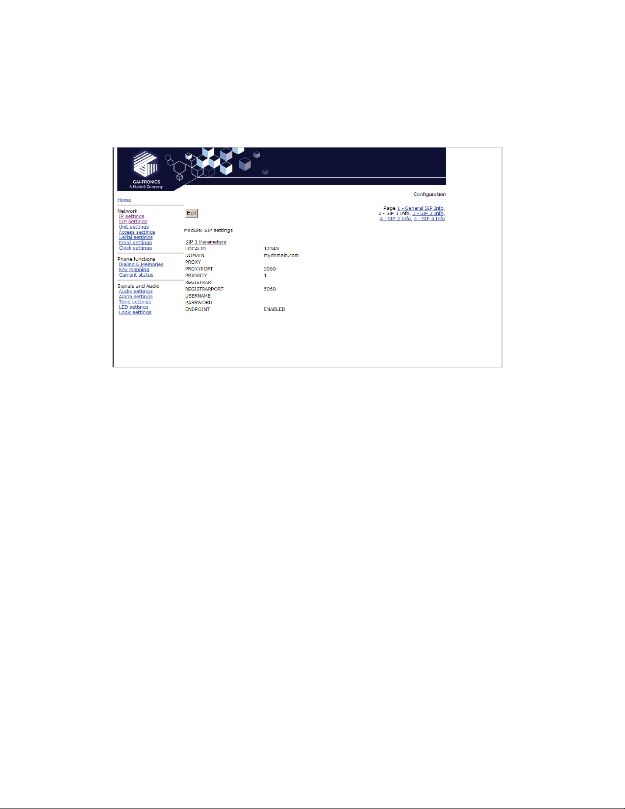
5.4 SIP settings
The SIP settings page is used to view or change parameters specific to the SIP signalling
protocol. GAI-Tronics VoIP phones can hold details of up to 4 SIP proxies. If the phone is
unable to register or make a call it can fail over to the next in a prioritised sequence. There is
a SIP Info page for each of the 4 possible endpoints, and a General SIP Info page containing
details common to all. The 4 endpoint pages are sub pages of the General page shown
below:
LOCALPORT: Configures the port number used for the local SIP signalling socket.
Default value: 5060
PROXYFAILOVERSTATUSES: This field contains a list of SIP error codes that will trigger a
fail over from one proxy to the next. Codes are 3 digits and the wildcard character “x” can be
used (ie 5xx would include any code from 500 to 599 inclusive). Codes are separated by
commas. Maximum field length 79 characters, ie 20 codes. The default list is 5xx, 6xx, 49x,
403, 406, 9xx. Codes are as defined in RFC3261 except 9xx, which is defined as "time-out"
and should always be included in the list.
Note that there are two failover mechanisms: one for proxies (defined here) and a second for
memories (defined in section 5.10.3). If a call fails due to a proxy error, the phone will then try
to place the call to the same number on the next proxy. If the call fails due to an endpoint
problem (for example "busy"), the phone will try the next number in the list, on the current
proxy.
DONTSTARTMEDIAATRING: This setting is not normally required. It can be used to delay
the sending of media packets to end points until the call has been answered. Only required if
problems are encountered with certain types of end point. Default value: OFF.
VoIP Telephone Configuration Guide Page 19 of 88
Page 20

GAI-TRONICS
3XED
SENDDTMFLAST: This setting is not normally required. It can be used to reorder the codec
sequence to end points, so that the DTMF codec is sent last. Only required if problems are
encountered with certain types of end point. Default value: OFF
RTPTOS: Sets the value of the TOS/Diffserv field in the UDP packets carrying RTP data. This
value prioritises traffic over the network to provide QoS (Quality of Service) for voice, see
RFC2474. Valid values are 1->63 (Default value = 46
SINGLEPTIME: Certain endpoints can only accept a single audio packet time regardless of
CODEC (see AUDIO page). This field forces a single packet time to the value set in ms.
Valid values are 0 to 100, where 0 disables the feature allowing codecs to use the packet
times set on the AUDIO page. Default value 0.
SENDMULTIPARTMIME: This option is for future enhancement and should always be set to
‘OFF’. Default value OFF.
NEWBRANCHONAUTHBYE: This is a legacy option that is no longer used, and must always
be set to 'ON'. Default value 'ON'.
MODE: This field sets whether multiple proxies and registrars are used serially or
concurrently. If set to SERIAL the phone will attempt to register with the next priority registrar
if registration with the current one fails. If set to MULTIPLE it will attempt to maintain
registration with all enabled registrars, and will use the priority sequence for outbound call
failover. Default value: SERIAL. When only a single proxy / registrar is enabled, set this
value to SERIAL to ensure any registration failure is detected quickly.
REGTIMEOUT: Sets the Registration timeout value (in seconds) that will be suggested by the
telephone to a Registrar. Following the expiry of this timeout, the telephone will be
deregistered and then automatically attempt to re-register. (Value range: 0 to 2
value: 3600) The registration server can ignore or override this suggested time.
REREGTIMEOUT: Sets a period in seconds after which the phone will force a re-registration
period and the server cannot override it. Disabled if set to zero. Default value 0. This field
can be used to ensure that registration is maintained for this particular phone, regardless of
the general settings on the registration server. For example, if this were an emergency
phone, setting this field to 30 would force re-registration every 30 seconds even if the server
normally only refreshes registration once an hour. In this way, if the proxy server fails or
becomes unavailable, the phone can detect it quickly and either attempt to register with the
)
32
-1, default
VoIP Telephone Configuration Guide Page 20 of 88
Page 21
GAI-TRONICS
next server in the priority list (if MODE is set to SERIAL) or direct calls to the next priority
server (if MODE is set to MULTIPLE).
3XED
Note that, if the current registrar becomes unavailable, the telephone may not be able to
make a call until it re-registers with the next.
5.4.1 SIP Info sub-pages:
Each of the 4 sub pages is identical, and is used to set parameters for each of 4 possible
proxies.
LOCALID & DOMAIN: together these set the URI (uniform resource identifier) of the phone.
In the example shown above the URI would be sip:12345@mydomain.com.
These values are used in the To:, From: and Contact: headers, and also in the registration
process with a registrar.
They will accept any alphanumeric string and their default values are both blank.
PROXY: Sets the IP address or the FQDN of the SIP proxy server to be used for
incoming/outgoing calls. Default value: blank
PROXYPORT: Sets the port number on the proxy used for SIP protocol signalling.
Default value: 5060
PRIORITY: Sets the failover sequence between the 4 pages.
REGISTRAR: Sets the address of the Registrar, either as an IP address or FQDN. The
registrar address and the proxy may or may not be the same, but the address for registration
must be set here. Default value: blank
REGISTRARPORT: Sets the port number to send the requests to. Is 5060 by default or if
unspecified.
USERNAME: Sets the username for the registrar authorisation realm. (Default value: blank)
PASSWORD:
ENDPOINT: Sets whether the subpage is ENABLED or DISABLED. (Default value:
ENABLED for SIP1, all others DISABLED).
Sets the password for the registrar authorisation realm. (Default value: blank)
VoIP Telephone Configuration Guide Page 21 of 88
Page 22
GAI-TRONICS
3XED
Note that the Proxy address could also be that of a peer-to-peer entity, allowing the unit to
make a direct peer-to-peer to connection. This can provide an extra level of resilience,
allowing the unit to fall back to a peer to peer call in the event that all proxy servers become
unavailable
5.5 Unit settings
The Unit page is used to set parameters for how the unit interfaces to the network, including
configuration file updates.
VoIP Telephone Configuration Guide Page 22 of 88
Page 23

GAI-TRONICS
3XED
HOSTNAME: Sets the unit host name. Maximum 15 alphanumeric characters (a-z, A-Z , 0-9).
Default Value is a unique string starting with "GT" and followed by the serial number of the
main circuit board inside the phone (referred to as the "Board serial" on the home page). The
host name identifies the unit on the network, and is also used in email and syslog messages
to identify the source of the message. If using DHCP, this field must be kept unique for each
phone on the system.
UPDATE SERVER: Sets the address of the host running the TFTP server. (Valid values: IP
address or FQDN. Default value: blank)
UPDATE FILE: The name of the update control file on the update server. This name may
contain the macro symbols %m, %h and %i. These symbols are expanded to the MAC
address, host name and IP address respectively. (Default value: blank)
UPDATE INTERVAL: Forces the unit to attempt a file download every X hours where X can
be an integer value between 0 and 1000. A value of 0 disables the periodic update request.
The default value is 1. Any non-zero value will cause the unit to attempt a configuration file
download at boot time.
HELPSERVER: Sets the default address for the Help web page reached from the link on the
home page. The default value is http://www.gai-tronics.co.uk/voipsupport.htm, but it can be
changed to any appropriate page available on the network.
LAN SPEED: Sets the speed or auto negotiation status for the WAN Ethernet port. Valid
values: 10, 100 or AUTO. Default value: AUTO. If the speed is auto negotiated the duplex
setting has no effect.
LAN DUPLEX: Sets the duplex value for the WAN Ethernet port. Valid values: FULL or HALF.
Default value: FULL.
CONFIGID: Used by the configuration upgrade script to determine if the local configuration is
the same as the one it wants to upgrade to. If this matches the CONFIGVERSION line in the
update control file, no download will take place. Default value: blank.
ANI: Used as an identifying token to GAI-Tronics CMA Call Management Application. Default
value: "GAIPHONE". Maximum 12 characters.
DEFAULT_ANS_MODE: Sets the default answer mode. This mode will be used to answer a
call when ANSMODE1, ANSMODE2 and PAGEMODE are not triggered. Values available are
RING, PICK-UP, PAGE and STEALTH. RING is normal phone operation, where a button
must be pressed or handset lifted to answer an incoming call. PICK-UP is as described in
ANSMODE2 below. PAGE is as described in PAGEMODE below. STEALTH is as described
in ANSMODE1 below. Default value: ‘RING’.
The next 3 fields set “passwords” that can be used by GAI-Tronics CMA to activate 3 special
auto-answer modes, usually for hands-free telephone types.
ANSMODE1: Stealth auto-answer mode, where the telephone provides no indication of the
incoming call and immediately auto answers the call. The speaker is muted, and the
microphone gain is enhanced. Sending a DTMF ‘*’ during a call will change the unit to
ANSMODE 2. For activation from CMA, set this field to "aa1"
ANSMODE2: Sets Intercom auto-answer mode, where the telephone auto answers and
provides normal duplex audio, preceded by an announcement tone. For activation from CMA,
set this field to "aa2"
PAGEMODE: Where the unit auto answers and disables the microphone. A "splash" tone
(tone 9) is emitted from the speaker to alert those nearby of an impending page
announcement. The output level of the speaker is increased to its maximum level. For
activation from CMA, set this field to "aa3"
VoIP Telephone Configuration Guide Page 23 of 88
Page 24

GAI-TRONICS
3XED
At the bottom of the UNIT page are three action buttons:
Update Now: Causes the phone to fetch the update file immediately.
Reboot Now: Causes the unit to reboot.
Reset to defaults: Causes the unit to reset to a predefined default configuration, effectively
returning it to the settings it had when it left the factory. WARNING: this will undo any
configuration changes, including returning the IP address and net mask to their default, static
values of 192.168.1.2 and 255.255.255.0. It will also reset the username and password to
defaults.
5.5.1 Audio Path Test
Audio Path Test (APT) is a factory option which must be specified at order time. If the phone
was not ordered with APT, these controls will not appear on the UNIT page.
The purpose of APT is to send a specific audio tone from the earpiece or speaker of a
telephone and then check that it is correctly received by the microphone. This will then verify
that both microphone and speaker are functioning.
APT appears as an alarm on the ALARMS page, and can be set to report via Syslog and / or
email like any other alarm, with some differences as listed below.
The test can be set to run automatically or triggered manually using the controls below:
APTENABLE sets whether APT is on or off
APTTIME sets a start time (24h clock) and test interval (in hours). The field should contain
first the time in hours and minutes separated by a colon (:), followed by a comma,(,) followed
by the interval in hours (range 1-24). Automatic testing will start at the specified time and
repeat every specified interval until 00:00 midnight the next day. The cycle will then repeat
the next day and so on. Default is 00:00,24 meaning that the test will perform once per day at
midnight.
APTCOUNT sets the number of tests that will be performed at each interval. Range is 1-10.
Default is 1, but it can be increased to repeat the test at each interval.
APTOKCOUNT sets the number of tests that must pass at each interval to be classed as a
successful test. Default value is 1. APTOKCOUNT must always be <= APTCOUNT. For
example if APTCOUNT were set to 3 and APTOKCOUNT to 2, the test would be deemed to
VoIP Telephone Configuration Guide Page 24 of 88
Page 25

GAI-TRONICS
have passed if 2 pass readings out of 3 were recorded. This feature is to allow for potential
disruption in areas of high ambient noise.
APTREPORT sets whether or not APT will send reports every time the test passes. Normal
alarms only report if they change state; setting APTREPORT to ON will cause the phone to
send a regular report confirming that it's acoustic components are healthy. By inference this
report also confirms that the phone is powered, running and connected to the network so it
also provides a useful general health check. If the test fails, the phone will not send repeated
reports until at least APTOKCOUNT tests pass again.
APT now will start an APT test within 60 seconds. This button will only start a test if
APTENABLE is set to ON.
3XED
5.6 Access settings
The Access settings page allows the user name and password to be changed.
USERNAME: Can be up to 30 characters long, and can contain only the alphanumeric
characters a-z, A-Z , 0-9 . The default value is “user”. The Username cannot be blank.
IMPORTANT: The word ‘root’ is a reserved username and must not be used or assigned a
password. Setting a user name of "root" will make it impossible to access the phone, and will
require a reset to factory defaults.
PASSWORD: Can be up to 30 characters long, and can contain only the alphanumeric
characters a-z, A-Z , 0-9 . The default value is "password". Password can be blank if
required.
Note: please make sure to record the user name and password securely. They will be
required to access the phone every time, whether by web page, command line or
configuration file. In the event that the username and password are lost, the unit will
need to be reset to factory defaults. This can be done by holding down a button on the
main circuit board. See section 10.
VoIP Telephone Configuration Guide Page 25 of 88
Page 26

GAI-TRONICS
3XED
At the bottom of the Access page are a series of counters showing how many unsuccessful
access attempts have been made to this phone, and how many times it has been rebooted.
The counters can be reset using the "Reset counters" button.
5.7 Serial settings
The Serial settings page is used to set the speed for communication on the serial port.
VoIP Telephone Configuration Guide Page 26 of 88
Page 27
GAI-TRONICS
Speeds available (from a drop-down list) are: 9600, 19200, 38400, 56700 & 115200 baud.
The default value is 115200.
The other parameters for serial comms are: 8 data bits, 1 stop bit, no parity.
3XED
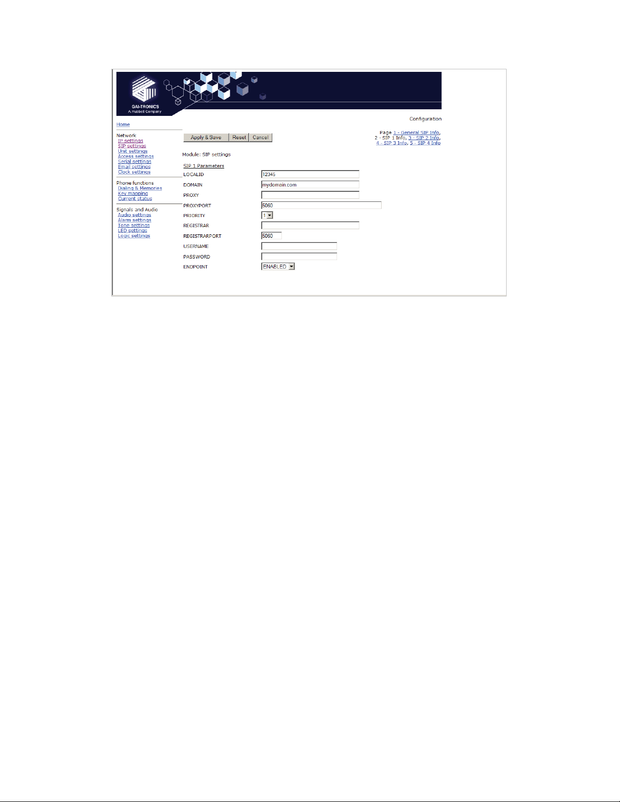
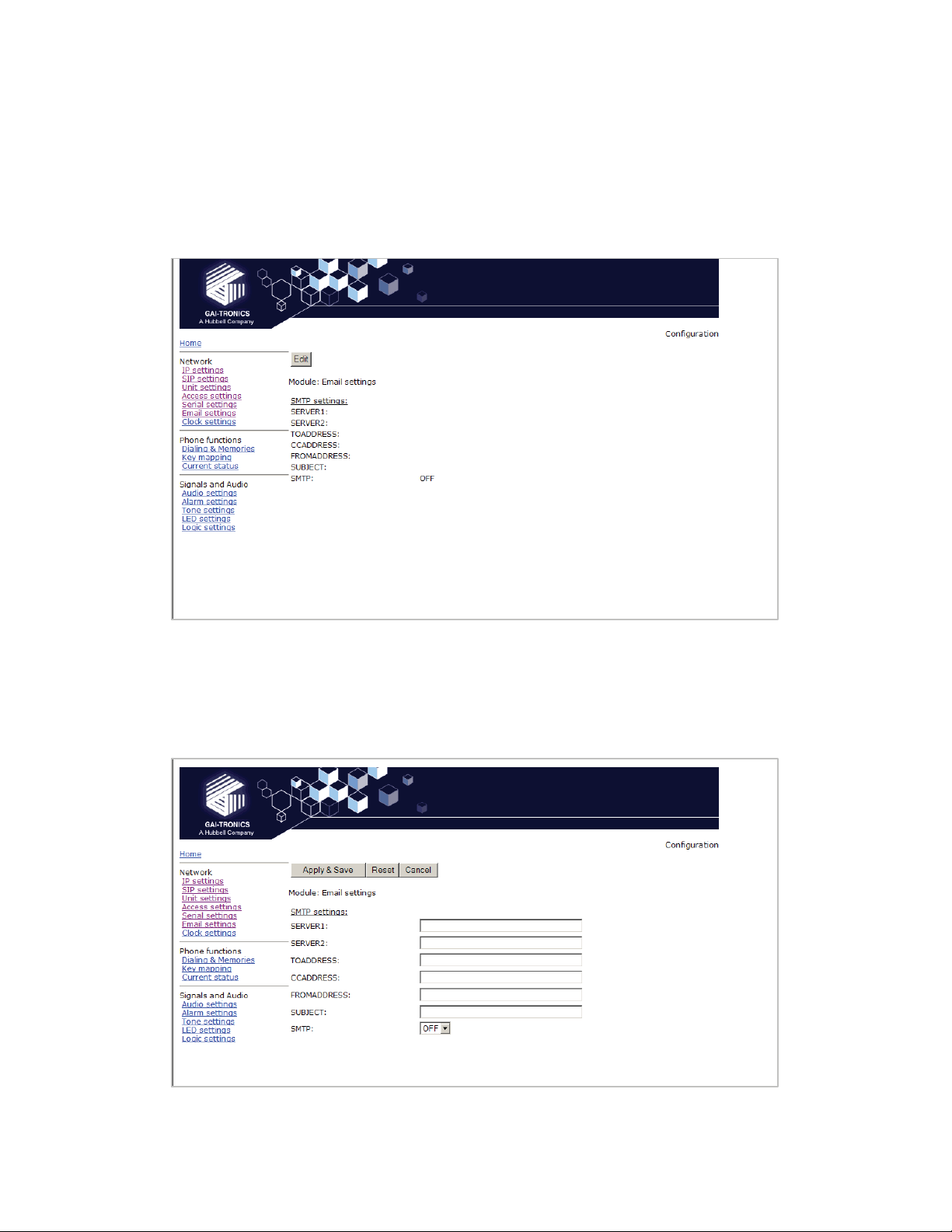
5.8 Email settings
The telephone can report various alarm and input conditions via email (see the ALARMS and
LOGIC pages in sections 5.14 and 5.17). The Email settings page is used to set the
parameters required.
SERVER1: Sets the primary SMTP server, as an IP address or a FQDN
SERVER2: Sets the secondary SMTP server, as an IP address or a FQDN, for redundancy.
TOADDRESS, CCADDRESS & FROMADDRESS: Set the email addresses that will appear
in the message. Note that the phone can send the message to two separate addresses (TO
& CC) Each of these fields can contain a single email address of the form abc@xyz.com
SUBJECT: Sets the subject that will appear with each email message from this unit.
SMTP: enables or disables email.
VoIP Telephone Configuration Guide Page 27 of 88
Page 28

GAI-TRONICS
3XED
5.9 Clock settings
The telephone does not include a battery backed real time clock, but will keep time based on
updates from an SNTP server. It can also adjust for daylight savings time by setting DST
start and end dates & times. The clock settings page is used to set the required
parameters.
SNTP: Sets the address for the SNTP server to be used, as an IP address or a FQDN.
SNTPINTERVAL: Sets the interval, in minutes, between SNTP update requests. Default is
60.
TIMEZONE: Sets the current time zone for local time from a dropdown list. See section for a
full list of available timezones.
FORMAT: Sets the date format to either UK (DD/MM) or US (MM/DD) style.
The remaining parameters on this page set the behaviour of the internal clock for daylight
savings time (DST). The normal default is for the clock to advance by one hour between the
last Sunday in March and the last Sunday in October, with the changes becoming effective at
2am on each of these days. To achieve this, the settings are:
ADJUST
OFFSET
STARTDAY
STARTDOW
STARTMONTH 3
STARTWOM
STARTTIME
ENDDAY
ENDDOW
ENDMONTH
ENDWOM
ENDTIME
Where:
ADJUST: Sets whether automatic Daylight Savings Time adjustment is on or off.
OFFSET: If DST is on, sets the offset. Default is +01:00
The remaining 10 parameters on this page set the start and end of the DST period:
ON
+01:00
0
1
8
02:00
0
1
10
8
02:00
VoIP Telephone Configuration Guide Page 28 of 88
Page 29

GAI-TRONICS
STARTDAY: Sets the day of the month on which DST begins:
• 1 -31 for days of month
• 0 ignore this value and use STARTDOW value
• Default is 0
STARTDOW: Sets the day of the week on which DST begins (1 - Sunday, 7 - Saturday).
Default value is 1.
STARTMONTH: Sets the Month in which DST will begin (Default value is 3).
STARTWOM: Sets the week of the month in which DST will begin. Valid values are 1 - 6,
where 1 is the first week and each subsequent number is a subsequent week. 8 signifies the
last week of the month regardless of which week the last week is (Default value is 8).
STARTTIME: Sets the hour of the day and the minute of the hour on which the unit will start
to use the DST offset if enabled, in the 24-hour format. Default = 02:00.
ENDDAY: sets the day of the month on which DST ends:
• 1 -31 for days of month
• 0 ignore this value and use ENDDOW value
• Default is 0
ENDDOW: sets the day of the week on which DST ceases (1 - Sunday, 7 - Saturday).
Default value is 1.
ENDMONTH: sets the Month in which DST will cease to operate (Default value is 10).
ENDWOM: sets the week of the month in which DST will cease. Valid values are 1 - 6, where
1 is the first week and each subsequent number is a subsequent week. 8 signifies the last
week of the month regardless of which week the last week is (Default value is 8).
ENDTIME: sets the hour of the day and the minute of the hour on which the unit will cease to
use the DST offset if enabled, in 24 hour format. Default = 02:00.
3XED
5.10 Dialling & Memories
The dialling and memory pages are used to set various "dialling" actions - ie how the
telephone initiates calls.
Depending on the keypad layout (see Key mapping page, section 5.11), the telephone may
have a numeric keypad, memory buttons or both.
VoIP Telephone Configuration Guide Page 29 of 88
Page 30

GAI-TRONICS
The numeric keypad is used to enter a number one digit at a time, whereas memory buttons
are used to dial complete, predetermined numbers.
Each memory button is assigned a memory list, consisting of one or more memories.
Calls started from memory buttons automatically divert to the next number in the list if the call
fails, as described below.
3XED
5.10.1 Memories sub-page
The telephone can store 20 call destinations, shown on the first Dialling & Memories
page.
Each entry has a MEMORY field, which can be a string of dialable characters or a SIP URI.
Dialable characters are the digits 0-9, and the letters A,B,C and D.
Each entry can also be assigned a COMFORT string, which is a string of digits that will be
played back to the user as DTMF when the call is being set up. This simulates the dialling
digit tones heard on a normal telephone. If these comfort digits are required, the comfort
string must be entered, even if the memory itself is a number.
Note these memories are not assigned directly to memory buttons - they must be called up in
memory lists on the next page.
VoIP Telephone Configuration Guide Page 30 of 88
Page 31

GAI-TRONICS
5.10.2 Memory Lists sub-page.
3XED
The telephone can hold up to 11 memory lists (0-10). Each list can be mapped to a button
(for example if the key mapping page shows a button marked MEM1, this will use memory list
1). Refer to the Key mapping page (section 5.11) for the buttons available in this phone. List
0 is the Emergency List and is mapped to a button designated as "Emergency" if fitted.
A list can also be set to activate as soon as the handset is lifted - see the "Basic Info" subpage.
Each list can contain up to 20 memory entries, separated by commas. For example if you
wanted the MEM1 button to call memory 1, if that failed to then call memory 5, and if that
failed call memory 10, you would enter "1, 5, 10" in the list box for list 1. When a memory list
in invoked, the telephone will attempt to place a call to each memory in the list in sequence
until a call is successful or it reaches the end of the list.
Each memory can appear in more than one list.
See the "Basic Info" sub-page for valid call fail causes.
Each list can also be set to "Wake and Dial". With this set to ON, the telephone will come off
hook and start to process the list as soon as the appropriate button is pressed. This is
normally set for hands-free telephones and help points without a separate "ON" button, but
can be set for handset phones if required.
Once a call is connected, pressing a memory button will cause DTMF to be sent if the first
entry in its memory list consists of dial-able characters.
VoIP Telephone Configuration Guide Page 31 of 88
Page 32

GAI-TRONICS
5.10.3 Basic Info sub-page.
This page is used to set some additional parameters to do with dialling.
3XED
OFFHOOK: Sets a memory list number to be invoked when the handset is taken off hook (in
a handset model) or when an "ON" button is pressed (on a hands-free model).
The next 3 parameters govern how the telephone decides whether or not the user has
entered the complete number when dialling manually:
MAXLEN: Sets the maximum number of dialable characters that can be entered manually
before the telephone assumes that the number is complete and starts the call. Range is 1-99,
default value 25.
DIALTIME: Sets the inter-digit timeout value in seconds. Once the user has entered the off
hook state, then failure to receive another digit within the timeout period will result in the call
being initiated with the dialled digits received so far. A value of 0 seconds disables the use of
the inter-digit timeout. The default value is 5 seconds. The maximum is 20 seconds.
TERMINATOR: Sets the dial string terminator character to be either #, * or if omitted (not
used). The default value is blank (not used). If the user dials the selected character the call
setup will be initiated.
CALLLIMIT: sets the maximum time allowed for a call in minutes. The range is 0 – 240 in
minutes. The value 0 disables the timer. The default value is 0. The call is terminated when
this timer expires.
PRECALL: Sets length of time in seconds that a phone will remain in the initial off hook state
generating dial tone without a dialling key being pressed. After this delay the phone will cease
dial tone and enter the on hook state even if the hook switch is off hook. The value 0 disables
this timeout. The default value is 30. Maximum is 60.
CALLFAIL: Sets the length of time that the phone will play tone 1 (dial tone) after the call has
ended. The default value is 30 seconds. The value 0 disables this timeout. Range is 0-30
VoIP Telephone Configuration Guide Page 32 of 88
Page 33

GAI-TRONICS
FAILOVERCAUSES: Comma separated list of cause codes that would allow the phone to try
the next entry in a list of memories. It is in no particular order. The cause codes are as
defined by Q.931 - See table below. The default list is:1,17,18,21,27,38,41,50,88
Code Cause SIP Clearance Code Comment
0 or
16
1 EndedByNoUser Failure_NotFound (404)
16 EndedByCallerAbort
17
18 Time out Request time out (408)
21
21 EndedByRefusal Default All Others
27 EndedByConnectFail
38 EndedByTransportFail
41 EndedByTemporaryFailure Failure_RequestTimeout (408)
50 EndedBySecurityDenial Failure_Forbidden (403)
88
Note that there are two failover mechanisms: one for memories (defined here) and a second
for proxies (defined in section 5.4). If a call fails due to a proxy problem, the phone will then
try to place the call to the same number on the next proxy. If the call fails due to an endpoint
problem (for example "busy"), the phone will try the next number in the list, on the current
proxy.
REMOTEALERTINGTIMEOUT: sets the maximum length of time in seconds that the phone
will ring on an outgoing call before timing out and returning "Number Unobtainable" (Tone 6)
to the user. A value of 0 disables the timer, meaning it will ring until the caller hangs up or the
remote end refuses the call. Range is 0-600. Default value 0.
LOCALALERTINGTIMEOUT: sets the maximum length of time in seconds that the phone will
ring on an incoming call before timing out and returning a "no answer" result to the caller. A
value of 0 disables the timer, meaning it will ring until the caller stops ringing. Range is 0-600.
Default value 0.
REMOTEALERTINGTIMEOUTCAUSECODE: sets the cause code (from the table above)
that will be entered in the call description record (CDR) if an outgoing call times out without
being answered. Default value 18.
LOCALALERTINGTIMEOUTCAUSECODE: sets the cause code (from the table above) that
will be entered in the call description record (CDR) if an incoming call times out without being
answered. It also sets the failover code that is returned to the calling party. Default value 18,
which will send a failover code of 408 from the table above.
EndedByRemoteUser
EndedByLocalUser
EndedByRemoteBusy Failure_BusyHere (486) Causes NU
EndedByAnswerDenied Declined Local user
EndedByCapabilityExchange Failure_UnsupportedMediaType
Call ended
(415)
3XED
normally
tone to be
played out.
refused call
5.11 Key mapping
The Key Mapping page shows the key map of the telephone, and also controls code
activation for the phone's relays. The key map is factory configured to the hardware and will
vary according to the precise model supplied (an 18 button version is shown) . The keymap
cannot be changed by users.
VoIP Telephone Configuration Guide Page 33 of 88
Page 34

GAI-TRONICS
3XED
The table below lists all the possible key functions:
Key Function
0 Dials a ‘0’.
1 Dials a ‘1’.
2 Dials a ‘2’.
3 Dials a ‘3’.
4 Dials a ‘4’.
5 Dials a ‘5’.
6 Dials a ‘6’.
7 Dials a ‘7’.
8 Dials an ‘8’.
9 Dials a ‘9’.
* Dials a ‘*’.
# Dials a ‘#’.
A Dials an ‘A’.
B Dials a ‘B’.
C Dials a ‘C’.
D Dials a ‘D’.
MUTE Toggle action key to silence/enable the transmission of audio from the
unit. Usually assigned to a key marked "S" (for Secrecy)
RECALL Defined below.
LNR Last Number Redial
ONHOOK Clears a call and puts the phone into the on hook state. Usually assigned
to a key marked "OFF"
OFFHOOK Answers a call or puts the phone into the off hook state ready to dial.
Usually assigned to a key marked "ON"
TOGGLEHOOK Toggle action key to take the phone on and off hook.
MEM 1, MEM 2
etc., to MEM 10
Attempts to initiate a call using Memory List 1, Memory List 2, etc., to
Memory List 10.
VoIP Telephone Configuration Guide Page 34 of 88
Page 35

GAI-TRONICS
Key Function
EMERGENCY Overrides any existing call and attempts to initiate a call using Memory List
0. Other keys can be inhibited during an emergency call - see below.
PULSE Activates any output configured with a "PULSE" keyword on the Logic
page (section 5.17). The output(s) will remain active for the duration of the
TIMER setting.
PULSE1 Activates Output 1 if it is configured with a "PULSE" keyword on the Logic
page. The output will remain active for the duration of the TIMER setting.
PULSE2 Activates Output 2 if it is configured with a "PULSE" keyword on the Logic
page. The output will remain active for the duration of the TIMER setting.
VOLUMEUP Increases audio output level (either HANDSETVOLUME or
HANDSFREEVOLUME as appropriate)
VOLUMEDOWN Decreases audio output level (either HANDSETVOLUME or
HANDSFREEVOLUME as appropriate)
VOLUMENEXT Steps the audio output volume to the next level, where the levels are
defined as current volume setting, midway to maximum, and maximum. A
further press will loop the volume back to current. Affects either
HANDSETVOLUME or HANDSFREEVOLUME as appropriate
GAINUP Increases HANDSETGAIN or HANDSFREEGAIN as appropriate.
GAINDOWN Decreases HANDSETGAIN or HANDSFREEGAIN as appropriate.
NOEFFECT Key is disabled.
The keypad related fields are:
INHIBIT: If the telephone has an "emergency" button, and a call started from this button is in
progress, one or more of the following buttons can be inhibited by entering keywords in this
field:
DIGIT will inhibit any button capable of generating a digit
MEMORY will inhibit any memory-dial button
CLEAR will inhibit any button capable of clearing or ending a call.
The keywords can be entered in any order and must be separated by a plus (+) character.
For example to inhibit all 3, enter "DIGIT+MEMORY+CLEAR"
The keyword NONE (which must be used on its own) will disable the inhibit function, and is
the default setting. The field cannot be blank.
RECALL: If the telephone has a Recall button, it can be used to activate the volt-free contact
outputs or LEDs of another telephone on the network. Enter the IP address of the remote unit
here. Any OUPUT or LED set with a GENERATE action of PULSE in the remote phone will
be activated when the Recall button is pressed on the local phone. (See LED and LOGIC
pages, sections 5.16 & 5.17)
3XED
5.11.1 Activating relays using DTMF codes
The phone’s 2 relays can be activated remotely using DTMF codes. When the phone is in a
voice call, if it receives a DTMF tone sequence that matches any of the fields below, the
designated relay will activate accordingly. Any sequence must be between 4 and 6 digits,
and is restricted to the numbers 0-9, characters A,B,C & D and the characters * and #. The
default values are all blank. Note that entering duplicate sequences for different actions on
the same relay may cause unpredictable results and the phone will not check for it. Care
must also be taken to ensure that DTMF can be transported reliably from the remote phone to
this unit, in terms of codec compatibility, in band / out of band transport etc.
The code activation fields are:
RELAY1ONCODE, RELAY2ONCODE: matching one of these codes will cause the
designated relay to turn on until instructed to turn off again or power is lost.
RELAY1OFFCODE, RELAY2OFFCODE: matching one of these codes will cause the
designated relay to turn off.
RELAY1PULSECODE, RELAY2PULSECODE: matching one of these codes will cause the
designated relay to turn on for a period defined by RELAY1PULSELEN or
RELAY2PULSELEN as appropriate and then turn off again.
RELAY1PULSELEN, RELAY2PULSELEN: define the period in seconds that the designated
relay will turn on for. Default value is 4, range is 1-60.
VoIP Telephone Configuration Guide Page 35 of 88
Page 36

GAI-TRONICS
3XED
5.12 Current status
The Current status page shows the status of any existing call (including "OnHook" if
appropriate), the 4 inputs, 2 outputs and the registration status of the 4 proxies as configured
on the SIP sub pages. There are no changeable parameters on this page.
Note that the input status reflects the settings on the Logic page (section 5.17). If the input is
set to detect "NONE", the status will report as Disabled. If the input is set to detect either ON
or OFF (or both), the status will report as follows:
External contact SENSE NORMAL SENSE INVERT
VoIP Telephone Configuration Guide Page 36 of 88
Page 37

GAI-TRONICS
Closed OFF ON
Open ON OFF
3XED
5.13 Audio settings
This page sets various audio parameters within the telephone
CODEC: This setting chooses the CODEC order of preference that will be used by the phone.
It is made up of a list of values from 1 to 6, separated by commas.
The values have the following meanings:
1 = G.711 A-law
2 = G.711 u-law
3 = G.722
Example: 6,5,4 would set the order of preference to be G.723.1 ACELP followed by G.723.1
MP-MLQ followed by G.729. None of the other codecs would be included.
NOTE: If codecs 5 & 6 are both used, they must be next to one another in the list.
SAMPLE: Sets the sample period for the G711, G722 and G 729 codecs to be either 10 or
20ms (individually). Default setting is 20ms.
NOTE: the sample size cannot be bigger than the packet size (packet size = frames per
packet x frame period). Normally the packet size will be at least 20ms, but if you have set a
low packet size (see below), you may need to set the sample period to 10ms.
4 = G.729 a/b
5 = G.723.1 MP-MLQ (6.3kbps)
6 = G.723.1 ACELP (5.3kpbs)
FRAMES: sets the number of audio sample periods or “frames” per IP packet.
Default values:
G.723.1 = 1. Each frame is 30ms (20 or 24 bytes), range is 1-4 frames
G.729 = 2. Each frame is 10ms (10 bytes), range is 2-10 frames.
G.711 = 20. Each frame is 1ms (8 bytes), range is 10-100 frames.
Increasing the number of frames per packet allows the bandwidth used on the IP connection
to be minimised, but increases transmission delay.
Decreasing the number of frames per packet reduces transmission delay but increases the
bandwidth used.
Note: the packet size (frame size x frames per packet) must be greater than the sample size
(see above). Make sure the SAMPLE size and FRAMES value for each codec are set
accordingly.
VAD: Enables or disables the use of Voice Activity Detection. This command is only valid for
G723 and G729 Codec settings. The default value is OFF. Note that when using the G729
codec, VAD must be set to on.
VoIP Telephone Configuration Guide Page 37 of 88
Page 38

GAI-TRONICS
3XED
DTMF: Sets the transmission of DTMF digits to be either in band or out of band. The default
setting is out of band, when DTMF is transmitted using RFC 2833.
DTMFPT: Sets the payload type parameter in the RTP packets when sending DTMF tones
'out-of-band' according to RFC2833. The default value is 96, but should be changed to 101
when using Cisco CallManager™.
DTMFPLAYBACK: sets whether DTMF tones are heard in the earpiece when digit buttons 09, * or # are pressed. Default value OFF.
HANDSETVOLUME: If the telephone is a handset model, this parameter sets the handset
earpiece volume. The range is 1-9 and the default value is 8. If the telephone is a hands-free
model, this setting has no effect.
HANDSFREEVOLUME: If the telephone is a hands-free model, this parameter sets the
speaker volume. The range is 1-12 and the default value is 3. If the telephone is a handset
model, this setting has no effect.
LINEVOLUME: This parameter is for future enhancements and has no effect.
Note: these volume settings set the starting volume within the available range. If the
telephone has a volume control button or buttons, these will only act up to the extents of the
range. In other words if the volume is set to its maximum on the web page, a “VOLUMEUP”
button will have no effect.
RINGERVOLUME: This parameter sets the ringer volume for both handset and hands-free
models. The range is 1-12 and the default value is 10.
HANDSETGAIN: If the telephone is a handset model, this parameter sets the handset
microphone gain. The range is 1-8 and the default value is 6. If the telephone is a hands-free
model, this setting has no effect.
HANDSFREEGAIN: If the telephone is a hands-free model, this parameter sets the
microphone gain. The range is 1-8 and the default value is 3. If the telephone is a handset
model, this setting has no effect.
LINEGAIN: This parameter is for future enhancements and has no effect.
JITTERMIN: Minimum size of dynamic jitter buffer. Range is 30-120. Default value is 30.
JITTERMAX: Maximum size of dynamic jitter buffer. Range is 30-120. Default value is 60.
VoIP Telephone Configuration Guide Page 38 of 88
Page 39

GAI-TRONICS
SIDETONE: Sets whether sidetone is on or off. Default setting is ON for handset models,
OFF for hands-free models.
3XED
SIDETONELEVEL: If sidetone is set to ON, this parameter sets its level. Range is 0-255,
default value 127. Take care when setting this level to ensure it is neither too high nor too low
for safe and acceptable performance.
5.14 Alarm settings
The telephone can recognise and generate several hardware and configuration fault condition
alarms. These alarms can be signalled to a remote site using two methods: -
• Syslog output over TCP
• SMTP mail message
VoIP Telephone Configuration Guide Page 39 of 88
Page 40

GAI-TRONICS
3XED
The available alarms are:
# Description Function Defaults
1 Handset
Integrity Loop
2 Configuration
Error
Signals a broken handset loop. Default ON and OFF times
5s
Signals that the configuration file
currently used by the unit has one or
Default ON time is 0, OFF
time is not applicable
more entry errors which have been
ignored.
3 Cold Reset Signals that the unit has reset due to a
power cycle.
4 Warm Reset Signals that the unit has reset due to an
internal software command or error.
5 Transducer
Not implemented.
Default ON time is 0, OFF
time is not applicable.
Default ON time is 0, OFF
time is not applicable.
Fault
6 Keypad Error Signals that a key has remained
pressed for the entire ONTIME period.
7 Key Hook Signals an off hook condition in excess
of the ONTIME when not in a call.
8 Register Fail Signals a failure to register with all
enabled proxy servers for a period in
Default ON and OFF times
6s.
Default ON time 30s, OFF
2s.
Default ON time is 360s,
OFF time is not applicable.
excess of the ONTIME. This alarm will
not occur if registration is maintained
with at least one of the enabled
registrars on the SIP pages.
9 Audio Path
Test
Signals a failure of an audio path test as
configured on the UNIT page.
ONTIME and OFFTIME
are not applicable.
Note that a status of "ON" means that
the test has failed.
For each alarm, the following parameters can be set:
REPORT: specifies if an alarm will be generated on assertion of an alarm condition only
(ON), on removal of the alarm condition only (OFF), on either event (ON+OFF) or not at all
(NONE)
STATUS: This field shows the current status of the alarm (not a changeable parameter).
VoIP Telephone Configuration Guide Page 40 of 88
Page 41

GAI-TRONICS
3XED
ONTIME: assigns alarm activation De-bounce Period to a specific alarm number. The alarm
event must be present at the start and at the end of the de-bounce Period before the alarm
status will be signalled using e-mail or syslog messaging (If enabled).
The period is specified in seconds and can take a value of 0 – 30,000. A value of 0 indicates
that there is no de-bounce period for this alarm type and a message will be generated
immediately the alarm event is detected.
OFFTIME: assigns an alarm removal De-bounce Period to a specific alarm number. The
alarm event must be absent at the start and at the end of the de-bounce period before the
alarm clearance will be signalled using e-mail or syslog messaging (if enabled).
The period is specified in seconds and can take a value of 0 – 30,000. A value of 0 indicates
that there is no de-bounce period for this alarm type and a message will be generated
immediately the alarm event is detected.
SYSLOG: enables or disables SYSLOG reporting for the selected alarm. Syslog settings are
on the IP setting page (section 5.3).
MAIL: enables or disables SMTP reporting for the selected alarm number. SMTP settings
are on the Email settings page (section 5.8).
MSG: Replaces the default text message ALARM <alarm_number> with the text entered
(maximum 40 characters). The status <on/off> is appended to the end of the text. If the MSG
value is blank, the default message is reinstated.
The message sent (for both mail and syslog reports), takes the form:
HOSTNAME COUNT TIME MSG ON/OFF
Where
HOSTNAME is from the Unit settings page (section 5.5).
COUNT is a volatile event counter (modulus 10000)
TIME is the event time and date from the unit's clock
MSG is the message set by the MSG field above. If no message has been set, the
default is "ALARM x" where x is the number shown against the alarms below.
ON/OFF is either the word ON or OFF according to the state of the alarm.
The History page displays a list of recent alarms (since last reset).
The "Edit" button on this page has no function.
VoIP Telephone Configuration Guide Page 41 of 88
Page 42

GAI-TRONICS
3XED
5.15 Tone settings
This page is used to set the various tones and signals generated by the telephone.
The telephone can generate 8 tone signals, usually set to emulate those used by normal
analogue phones:
Tone 1 - Dial: after taking the phone off hook but before dialling
Tone 2 - Stutter Dial: reserved for future use
Tone 3 - Ring: when a call has been placed but not yet answered
Tone 4 - Busy: when the called party is engaged
VoIP Telephone Configuration Guide Page 42 of 88
Page 43

GAI-TRONICS
3XED
Tone 5 - Congestion: when the call cannot connect due to network congestion
Tone 6 - Number Unobtainable: when the call cannot connect due to the endpoint not being
recognised
Tone 7 - Ring Signal: announcing an incoming call.
Tone 8 – Register Fail: When a call cannot be made due to registration failure
Tone 9 - Splash 1: Announcing an incoming PAGE call
Tone 10 - Splash 2 MRTP: Announcing an incoming multicast
Each tone can be configured by setting a tone frequency (ie the note), and the cadence (ie
the timing pattern). These are normally set to simulate exchange tones common to the
phone's location, but may be configured for any purpose, for example to give distinctive ring
tones to differentiate between phones mounted close together. A table of typical tones used
in various countries is included below, and the make up of the tones is explained as follows:
Frequency
Frequency No. Tone.
1 400 Hz
2 425 Hz
3 440 Hz
4 350 Hz + 450 Hz
5 400 Hz + 450 Hz
6 480 Hz + 620 Hz
7 20 Hz + 675 Hz
8 20 Hz + 1000 Hz
9 20 Hz + 1350Hz
10 30 Hz + 2575 Hz
11 2970Hz alternating with 3380Hz at 30Hz and maxed gains
12 220Hz
13 440Hz
Frequencies 1 to 6 are commonly used for call progress, whilst 7 to 10 are usually used for
ring signals.
For example dial tone in the UK is a compound tone of 350+450 Hz, corresponding to
frequency No.4.
Cadence
VoIP Telephone Configuration Guide Page 43 of 88
Page 44

GAI-TRONICS
The telephone sets the cadence of a tone using ON and OFF times. To allow for most
regional tone patterns there are 3 pairs of ON and OFF times - an initial pair, which is played
once only, and 2 subsequent pairs that are repeated one after the other until the tone stops.
(See diagram below).
Repeat
Start
ON1 ON2 ON3
OFF1 OFF2 OFF3
ON and OFF times are entered in units of 25ms (ie 1s is entered as 40) and are in the range
0 - 600.
To create a continuous tone, set any one of the ON times to a value (say 80), and all the
other ON and OFF times to 0.
3XED
5.15.1 Suggested Tone Settings for Various Countries:
UK No. Freq On 1 Off 1 On 2 Off 2 On 3 Off 3
Dial 1 4 80 0 0 0 0 0
Stutter Dial 2 4 0 0 30 30 0 0
Ring 3 5 0 0 16 8 16 80
Busy 4 1 0 0 15 15 0 0
Congestion 5 1 0 0 16 14 9 21
NU 6 1 0 0 80 0 0 0
Ring signal 7 10 0 0 16 8 16 80
Register Fail 8 4 0 0 78 2 0 0
US No. Freq On 1 Off 1 On 2 Off 2 On 3 Off 3
Dial 1 4 0 0 80 0 0 0
Stutter Dial 2 4 0 0 4 4 0 0
Ringback 3 3 0 0 80 160 0 0
Busy 4 6 0 0 20 20 0 0
Congestion 5 6 0 0 10 10 0 0
NU 6 1 0 0 80 0 0 0
Ring signal 7 10 0 0 80 160 0 0
Register Fail 8 4 0 0 78 2 0 0
France No. Freq On 1 Off 1 On 2 Off 2 On 3 Off 3
Dial 1 3 0 0 80 0 0 0
Stutter Dial 2 4 0 0 80 0 0 0
Ringback 3 3 0 0 60 140 0 0
Busy 4 3 0 0 20 20 0 0
Congestion 5 3 0 0 20 20 0 0
NU 6 3 0 0 20 4 0 0
Ring signal 7 10 0 0 60 140 0 0
Register Fail 8 4 0 0 78 2 0 0
Netherlands No. Freq On 1 Off 1 On 2 Off 2 On 3 Off 3
Dial 1 2 0 0 80 0 0 0
Stutter Dial 2 2 0 0 20 2 0 0
Ringback 3 2 24 176 40 160 0 0
Busy 4 2 0 0 19 19 0 0
Congestion 5 2 0 0 10 10 0 0
NU 6 2 0 0 40 4 0 0
VoIP Telephone Configuration Guide Page 44 of 88
Page 45

GAI-TRONICS
3XED
Ring signal 7
Register Fail 8 4 0 0 78 2 0 0
10 0 0 40 160 0 0
Portugal No. Freq On 1 Off 1 On 2 Off 2 On 3 Off 3
Dial 1 1 0 0 80 0 0 0
Stutter Dial 2 1 0 0 40 8 0 0
Ringback 3 1 0 0 40 200 0 0
Busy 4 1 0 0 20 20 0 0
Congestion 5 1 0 0 20 20 0 0
NU 6 2 0 0 8 8 0 0
Ring signal 7 10 0 0 40 200 0 0
Register Fail 8 4 0 0 78 2 0 0
Norway No. Freq On 1 Off 1 On 2 Off 2 On 3 Off 3
Dial 1 2 80 0 0 0 0 0
Stutter Dial 2 2 0 0 20 2 0 0
Ringback 3 2 0 0 40 160 0 0
Busy 4 2 0 0 20 20 0 0
Congestion 5 2 0 0 10 10 0 0
NU 6 2 0 0 80 0 0 0
Ring signal 7 10 0 0 80 160 0 0
Register Fail 8 4 0 0 78 2 0 0
Note that the ring signal frequency is not specified by any regulations or customs. Frequency
10 is shown in the examples above, but any could be used according to preference.
Splash tones are not country specific so are not shown above.
5.16 LED settings
The telephone, depending on model, can have up to 3 programmable LEDs, LED1, LED2 and
LED3, which can be configured using the LED Settings page.
Each LED has 3 parameter entry fields:
GENERATE: This field sets the function of the LED by the use of the following keywords:
VoIP Telephone Configuration Guide Page 45 of 88
Page 46

GAI-TRONICS
3XED
ON Sets the LED permanently on.
OFF Sets the LED permanently off.
PULSE +
Sets the LED to illuminate once only for the period defined by the
TIMER field, on receipt of a Recall signal from a remote phone.
MUTE + Sets the LED to indicate if the audio input is muted.
RING +
CALL +
Sets the LED to flash when an incoming call is ringing. The flashing
on /off periods are set by the CADENCE field.
Sets the LED to flash when an outgoing call is active. The flashing on
/off periods are set by the CADENCE field.
CONNECT + Sets the LED on when a call is connected.
HOOK +
INUSE +
Sets the LED on when the telephone is off hook, and off when it is
back on hook.
Sets the LED on when an incoming call arrives or when the user goes
off hook for an outgoing call, and off when the call ends.
Causes the LED to flash in time with the incoming ring signal cadence.
RINGCADENCE +
This cadence is set by the parameters for Tone 7 (TONES page,
section 5.15).
Sets the LED to flash when an outgoing call is ringing (but not yet
RINGOUT +
connected). The flashing on /off periods are set by the CADENCE
field.
PAGE +
Sets the LED to flash
a PAGEMODE call (see UNIT page, section 5.5). The flashing on /off
when a call is present that has been signalled as
periods are set by the CADENCE field.
Sets the LED to flash when the phone is registered with at least one
REGISTERED +
SIP server. Can be used as a “phone available” indicator. The
flashing on /off periods are set by the CADENCE field.
Sets the LED to flash whenever there is an outgoing call present that
EMERGENCY +
has been initiated by an EMERGENCY button. The flashing on /off
periods are set by the CADENCE field.
The ON and OFF keywords must be used on their own. The other keywords (indicated by a +
symbol in the table above), can be combined and entered in any order, separated by a plus
(+) character. For example to set an LED to flash when an incoming call is ringing, and
illuminate steadily when the call is connected enter RING+CONNECT.
TIMER: Sets the timer value for the PULSE command in seconds. Default value is 3. The
minimum is 0 & the maximum is 3600.
CADENCE: Sets the cadence for those keyword commands that require it. The cadence is
entered as two numbers separated by a colon (:) character, representing the on and off times
in tenths of a second. For example to set a cadence of 1 second on, half a second off, enter
10:5.
VoIP Telephone Configuration Guide Page 46 of 88
Page 47

GAI-TRONICS
3XED
At the bottom of the page is a mode entry box with a MODE button. The box offers 3 choices
from a drop-down menu. These preset the functions of LED1 and LED2 to mimic existing
analogue telephone models:
HELPPOINT: Sets LED1 to RING+HOOK, LED2 to OFF
DDA: Sets LED1 to HOOK+RINGOUT, and LED2 to CONNECT+RING.
OFF: Sets LED1 & LED2 both OFF
Clicking the MODE button has the effect of applying and saving the mode settings.
TIMER and CADENCE settings are not affected by the MODE (ie they must be set
independently).
VoIP Telephone Configuration Guide Page 47 of 88
Page 48

GAI-TRONICS
3XED
5.17 Logic settings
The Logic settings page sets the operation of the 4 auxiliary inputs and the 2 volt-free contact
outputs.
Inputs
The 4 auxiliary inputs are activated by connecting the relevant input terminal to a common
terminal via a volt-free contact. See
electrical lim
and
contact is closed it is deemed to be OFF. The sense can be inverted, see below:
The auxiliary inputs can be configured to report their status to a remote site using two
methods: -
• Syslog output over TCP
• SMTP mail message
For each input, the following parameters can be set:
DETECT: Specifies if an input will report being set to its ON condition only (ON), its OFF
condition only (OFF), on either event (ON+OFF) or not at all (NONE). The ON and OFF
states are affected by the SENSE setting below.
SENSE: If set to NORMAL, a contact closure will report as OFF. If set to INVERT, a contact
closure will report as ON. Default is NORMAL
SYSLOG: enables or disables SYSLOG reporting for the selected input. Syslog settings are
on the IP setting page (section 5.3).
MAIL: enables or disables SMTP reporting for the selected input. SMTP settings are on the
Email settings page (section 5.8).
MSG: Replaces the default text message Aux_in <input_number> with the text entered
(maximum 40 characters). The status <on/off> is appended to the end of the text. If the MSG
value is blank, the default message is reinstated.
The message sent (for both mail and syslog reports), takes the form:
HOSTNAME COUNT TIME MSG ON/OFF
Where
its. If the contact is open the input is normally deemed to be ON, and if the
External contact SENSE NORMAL SENSE INVERT
Open ON OFF
Closed OFF ON
appropriate installati
on guide for connection details
VoIP Telephone Configuration Guide Page 48 of 88
Page 49

GAI-TRONICS
HOSTNAME is from the Unit settings page (section 5.5)
COUNT is a volatile event counter (rolls over at 10000)
TIME is the event time and date from the unit's clock
MSG is the message set by the MSG field above. If no message has been set, the
default is " Aux_in x".
ON/OFF is either the word ON or OFF according to the state of the input, taking
account of the SENSE setting.
3XED
Outputs
The 2 outputs are both volt-free contacts, but their ratings differ. See
guide for c
Each output has 3 p
onnection details and electrical limits.
arameter entry fields:
appropriate installation
GENERATE: This field sets the function of the output by the use of the following keywords:
VoIP Telephone Configuration Guide Page 49 of 88
Page 50

GAI-TRONICS
ON Sets the output permanently on.
OFF Sets the output permanently off.
PULSE +
MUTE + Sets the output to indicate if the audio input is muted.
RING +
CALL +
CONNECT + Sets the output on when a call is connected.
HOOK +
INUSE +
RINGCADENCE + Causes the output to pulse in time with the ring tone cadence.
RINGOUT +
PAGE +
REGISTERED +
EMERGENCY +
The ON and OFF keywords must be used on their own. The other keywords (indicated by a +
symbol in the table above), can be combined and entered in any order, separated by a plus
(+) character. For example to set an output to pulse when an incoming call is ringing, and be
on steadily when the call is connected enter RING+CONNECT.
TIMER: Sets the timer value for the PULSE command in seconds. Default value is 3. The
minimum is 0 & the maximum is 3600.
CADENCE: Sets the cadence for those keyword commands that require it. The cadence is
entered as two numbers separated by a colon (:) character, representing the on and off times
in tenths of a second. For example to set a cadence of 1 second on, half a second off, enter
10:5.
Sets the output to activate once only for the period defined by the
TIMER field, on receipt of a Recall signal from a remote phone.
Sets the output to pulse when an incoming call is ringing. The pulsing
on /off periods are set by the CADENCE field.
Sets the output to pulse when an outgoing call is active. The pulsing
on /off periods are set by the CADENCE field.
Sets the output on when the telephone is off hook, and off when it is
back on hook.
Sets the output on when an incoming call arrives or when the user
goes off hook for an outgoing call, and off when the call ends.
Sets the output to pulse when an outgoing call is ringing (but not yet
connected). The pulsing on /off periods are set by the CADENCE
field.
Sets the output to pulse when a call is present that has been signalled
as a PAGEMODE call (see UNIT page, section 5.5). The pulsing on
/off periods are set by the CADENCE field.
Sets the output to pulse when the phone is registered with at least one
SIP server. Can be used as a “phone available” indicator. The pulsing
on /off periods are set by the CADENCE field.
Sets the output to pulse whenever there is an outgoing call present
that has been initiated by an EMERGENCY button. The pulsing on
/off periods are set by the CADENCE field.
3XED
5.18 Multicast settings
Multicast is a factory option which must be specified at order time. If the phone was not
ordered with Multicast, this page will not appear.
Multicast allows a single audio stream to be sent to multiple endpoints simultaneously, to
achieve multi-point paging or Public Address functionality over IP. As such it is only
applicable to telephones with a loudspeaking capability such as handsfree units and Help
Points
Multicast requires the use of a SIP server that specifically supports it, and each endpoint (ie
phone) must be individually configured to receive multicast packets.
When making a multicast call, the SIP server will send a paging request to a specific IP
address and expect multiple phones to accept and play the subsequent audio.
The GAI-Tronics phone can be programmed with up to 8 multicast IP addresses to allow the
receipt of multicasts from different sources or to enable zoning of multicasts.
Each multicast address can be assigned a priority to define which can override which.
A phone with multicast enabled can still make and receive normal calls. Normal calls can
also be assigned a priority level, defining whether calls can override multicasts or vice versa.
VoIP Telephone Configuration Guide Page 50 of 88
Page 51

GAI-TRONICS
3XED
TIMEOUT: sets an enforced delay (in seconds) between one Multicast session ending and
another beginning. Range 1-120. Default 120
SPEAKERVOLUME: sets the speaker volume during a multicast. Volume will revert to the
setting on the AUDIO page when the multicast session has ended. Range is 1 to 10, default
value 3.
Override level: sets the override level (between 0 and 8) for normal phone calls with respect
to the priority level set against multicast calls defined below. 1 is highest priority, 8 is lowest.
0 means no priority and will not override any multicast. For example, if override level is set to
5, a voice call will override a multicast having a priority of 6, but not one having a priority of 4.
If a voice call and a multicast have the same priority level the multicast will take precedence.
If an incoming call is made to a phone whilst a higher priority multicast is in progress, the
caller may hear the multicast audio but a speech call will not be connected to the phone until
the multicast has ended.
Note: Emergency calls started from the phone (ie using a button designated as an
Emergency button) will always override any normal or multicast call, regardless of priority or
override level.
The following fields can be set for 8 individual multicast sources:
ADDRESS: the phone will accept multicast calls sent to this address by the SIP server. Must
be an IP address complete with port, eg 242.0.1.75:5000. Reserved addresses for multicast
channels are normally in the range 224.0.0.0 to 224.0.0.255.
FILTER: Sets a range of acceptable multicast source IP addresses. The phone will only
accept a multicast if the source is within this IP address range. The format is 2 IP addresses
separated by a colon. The default is 0.0.0.0:255.255.255.255
PRIORITY: sets a priority level for this multicast with respect to other multicasts and normal
phone calls. The range is 0 to 8, with 1 being the highest priority, 8 being the lowest and 0
having no priority. If a higher priority event (multicast or phone call) occurs during an existing
multicast, it will be interrupted and resume after the higher priority event has finished.
OUTPUT1 : sets if OUTPUT1 is ENABLED or DISABLED during this multicast. If ENABLED
it will be in a permanently energised state, with no timing or cadence control. After the
multicast has ended it will revert to its function as defined on the LOGIC page.
OUTPUT2: sets if OUTPUT2 is ENABLED or DISABLED during this multicast. If ENABLED it
will be in a permanently energised state, with no timing or cadence control. After the
multicast has ended it will revert to its function as defined on the LOGIC page.
VoIP Telephone Configuration Guide Page 51 of 88
Page 52

GAI-TRONICS
3XED
TONE: sets if tone 10 (TONES page) is ENABLED or DISABLED during this multicast.
VoIP Telephone Configuration Guide Page 52 of 88
Page 53

GAI-TRONICS
3XED
6. Configuration File update
GAI-Tronics VoIP telephones can be updated by downloading files from a server. This
provides a powerful method of updating multiple units across a network. Security features are
built in to reduce the possibility of accidental or malicious damage. All 3 components of the
unit’s software can be upgraded:
• The configuration (equivalent to the settings on the web pages)
• The firmware
• The kernel (effectively the operating system on which the firmware runs)
These 3 elements can be downloaded independently, with the exception that if the kernel is
updated, the firmware must be updated at the same time, since it references the kernel
version.
The update process is as follows:
1. The telephone has 4 parameters that control updates (on the UNIT page):
• SERVER: the IP address of the host running the TFTP server
• FILE: the name of the update control file on the server
• INTERVAL: a period in hours between download attempts
• CONFIGID: used to identify the current configuration
2. Note that the update is initiated by the telephone. It can also be done on demand by
clicking the “Update now” button on the UNIT page. After the update occurs the
telephone will reset itself to activate the update - this means that web pages will be
unavailable for a few seconds.
3. The update control file is a small text file containing up to 13 lines, each of which starts
with a keyword. Normal routine updates would be configuration changes only, when the
update control file would contain only 4 lines. An example file would be:
USERNAME=user
PASSWORD=password
CONFIGVERSION=18but7
CONFIGFILE=VoIP3.cfg
Where:
USERNAME & PASSWORD are used by the unit to decide if this is a valid update.
CONFIGVERSION is the string that will be checked to see if the configuration needs
upgrading. (If this matches CONFIGID in the telephone, no update will be carried out)
CONFIGFILE is the configuration file to upgrade to.
4. The configuration file itself is again a text file, composed with a fixed syntax (see section
6.1 below). An example of a simple configuration file to change 4 memories and put them
into 2 memory lists (the same example as shown in the FAQs at the start of this guide) is
shown below:
[DIALPLAN]
MEMORY=1 888
MEMORY=2 sip:info@mydomain.com
MEMORY=3 sip:security@mydomain.com
MEMORY=4 223344@mydomain.com
COMFORT=1 888
COMFORT=2 223344
COMFORT=3 223344
COMFORT=4 223344
LIST=1 2, 3, 4
LIST=2 1
WAKEANDDIAL=1 ON
WAKEANDDIAL=2 ON
[UNIT]
CONFIGID=18but7
Note that the configuration file is divided into sections, with each section header in square
brackets. Note that the CONFIGID in the UNIT section is used to change the CONFIGID
in the phone to the CONFIGVERSION in the update control file. This provides an
indication for the current configuration in the telephone itself, and prevents repeated
downloading of the same file triggered by the UPDATEINTERVAL.
VoIP Telephone Configuration Guide Page 53 of 88
Page 54

GAI-TRONICS
3XED
5. In summary, configuration file updates are achieved using 2 files: an update control file
and a configuration file.
6. When the firmware (and kernel if required) need to be updated, the update control file is
expanded to its full form, for example:
USERNAME=user
PASSWORD=password
CONFIGVERSION=18but7
CONFIGFILE=VoIP3.cfg
SERVER=192.168.1.6
VERSION=1.1.11
ROOTFS=incaip.root.jffs2
USERFS=incaip.usrlocal.jffs2
KERNEL=1
KERNELFILE=uImage_quiet
KERNELMD5=ad785ffb47ccd95224f8844addc7ec05
ROOTFSMD5=f5d417c3b94a8b34e2c6afecfc985128
USERFSMD5=d5c978f26d351a9428d9c390fbb5e1ed
Where:
SERVER is the address from which the firmware and kernel files are downloaded.
VERSION is the version of the firmware code available.
ROOTFS & USERFS are filenames of the 2 files required to upgrade the firmware.
KERNEL is a flag that decides whether the kernel needs updating for this version of code.
(1 – needed, 0 – not needed)
KERNELFILE is the kernel file to upgrade to.
The xxxMD5 lines are the MD5 sums of the padded files to be upgraded to. This is to
ensure the integrity of the files.
7. If firmware or kernel upgrades are necessary, the files will be supplied by Gai-Tronics
together with the appropriate xxxMD5 codes.
8. All filenames used in this process, ie the FILE field on the UNIT page, and the
CONFIGFILE, ROOTFS, USERFS and KERNELFILE names in the update control file,
can contain the predefined macros %h (hostname), %i (IP address) or %m (MAC
address) or any combination of them in the filename string. Eg: ‘update.cfg%m’ would
expand to ‘update.cfg0001df123456’ (for a MAC address of 0001df123456).
VoIP Telephone Configuration Guide Page 54 of 88
Page 55

GAI-TRONICS
3XED
6.1 Configuration File Syntax
Configuration files are text files divided into sections. Each section comprises a header
followed by a series of configuration lines for parameters within that section.
Sections roughly correspond to the web pages, and every web page parameter can be set
using a configuration file.
The 15 possible sections are:
Section Name Section Description
ACCESS
ALARMS This section allows the configuration of the alarm control parameters
AUDIO
CLOCK
DIALPLAN
IP
KEY
LED
LOCAL
LOGIC
MULTICAST
SIP
SMTP This section permits the configuration and settings for the SMTP client.
TONES
UNIT
Each configuration file need only contain the sections required to be changed. Within each
section, only the parameters to be changed need to be included. Sections (and parameters
within each section) can be in any order. A configuration file will incrementally patch the
existing configuration
All section headers are enclosed within square brackets and followed by comment character
or a Carriage return / Line feed character combination.
Comments can be placed within the file by preceding the comment with the // symbol
combination and ending the line with a carriage return / line feed combination
Individual module configuration lines are made up of a configuration item identifier followed by
the = sign, and then any configuration values or parameters.
This section allows the configuration of the user access name and
password
This section facilitates the configuration of the analogue front-end
parameters and the treatment of the audio streams.
This section allows the configuration of parameters associated with the
time keeping facilities within the unit.
This section allows the configuration of parameters associated with the
dialling of destination telephone numbers, and associated dialling
parameters.
This section permits the configuration of the IP parameters specific to
this unit.
This section allows the configuration of the mapping between the
keypad and the associated key function.
This section allows the configuration of the function of the two LED
indicators
This section controls the configuration and settings of the Local
Asynchronous configuration port
This section accesses the configuration and settings of the relay
outputs and sensor inputs.
This section allows the configuration of multicast parameters. Only
available if the phone is factory configured for multicast.
This section allows the configuration of parameters specific to the SIP
signalling protocol.
This section allows the configuration of the units call progress tones,
and ring cadence information.
This section looks after various other miscellaneous functions and
configuration options for the unit
[Section Name]cr/lf
// this line is a comment
Item Identifier = value1 value2 value3
VoIP Telephone Configuration Guide Page 55 of 88
Page 56

GAI-TRONICS
The Item Identifier can consist of one or more words before the equals sign, the configuration
values or parameters follow the = character and are separated by spaces or tab characters.
The line is ended by a comment character combination (//) or a cr/lf combination.
3XED
6.2 Configuration File Commands
The table below lists the valid section names, the valid Item Identifiers within that section and
the allowable values that can be assigned to each item identifier. In some cases a fuller
description of the various options is contained in the section on the relevant web page above.
Configuration lines that are not understood will be ignored and processing will continue at the
next line. Configuration lines that are in the wrong section will be ignored, and processing of
the rest of the file will continue at the next line.
If an invalid or incorrectly positioned configuration line is encountered then an “Invalid
Configuration file” error will be generated and signalled as an alarm.
Commands will be read and actioned as the parser proceeds down the file. If a subsequent
command contradicts an earlier command, then the later command will be acted upon and
the earlier command overridden.
For Example:-
[ALARMS]
ALARM=1 ON //initial command is actioned
ALARM=1 ON+OFF // subsequent command is actioned overriding previous command
Multiple values for the same item identifier are permitted on the same line, and are separated
by space, comma or tab characters.
Example:-
[AUDIO]
CODEC=1,4,6 // Selects preferences as G.711 A-law, G.729 &
// G.723.1 ACELP in that order
An example configuration file is included in Section 8, showing entries in each section. This
example (or parts of it) can be used as a basis to construct files as required.
VoIP Telephone Configuration Guide Page 56 of 88
Page 57

GAI-TRONICS
Section Item Identifier Value(s) Comments
ACCESS
USERNAME UserName
PASSWORD Password
Sets the user name used in local or remote access to
be “UserName”. UserName can be up to 30
characters long, and can contain only the
alphanumeric characters a-z, A-Z , 0-9. The default
value is “user”. The Username cannot be blank.
Example USERNAME=franklin
IMPORTANT: The word ‘root’ is a reserved
username and must not be used or assigned a
password. Setting a user name of "root" will make it
impossible to access the phone, and will require a
reset to factory defaults.
Sets the password used in local or remote access to
be “Password”. “Password” can be up to 30
characters long, and contains only the alphanumeric
characters a-z, A-Z , 0-9. The default value is
password.
Example PASSWORD=sugar1
Note: please make sure to record the user name and password securely. They will be
required to access the phone every time whether by web page, command line or
configuration file.
In the event that the username and password are lost, the unit will need to be reset to
factory defaults. This can be done by holding down a button on the main circuit
board. See section 10.
3XED
ALARMS
ALARMx
(where x is 1 to 20)
See ALARMS web page
section (5.14) for alarm
descriptions and
appropriate settings
REPORT ON
REPORT OFF
REPORT ON+OFF
REPORT NONE
SYSLOG ON
SYSLOG OFF
MAIL ON
MAIL OFF
MSG “text”
ONTIME xxx
OFFTIME xxx
This command specifies if the alarm will be generated
on assertion of an alarm condition only.
Example ALARM4=ON
This command specifies if the alarm will be generated
on removal of an alarm condition only.
This command specifies if the alarm will be generated
on assertion and removal of an alarm condition.
This command disables, the generation of all alarm
reports for the alarm. The generation of alarms in the
status pages, and the generation of SYSLOG and
MAIL reporting are all disabled. The generation of
alarms must be reapplied for status reporting,
SYSLOG reporting and MAIL reporting if required.
The default value for all alarm conditions is NONE.
This command enables SYSLOG reporting for the
selected alarm number.
This command disables SYSLOG reporting for the
selected alarm number.
This command enables email reporting for the
selected alarm number XX.
Example ALARM6=MAIL ON
ALARM4=MAIL OFF
This command disables email reporting for the
selected alarm number.
This command replaces the default text message
ALARM ǻ<alarm_number> with the text entered as
the value after the = text.
The text is delimited by quote marks and is a
maximum of 40 characters. The status <on/off> is
appended to the end of the text.
This command assigns an activation de-bounce
period to a specific alarm number. See ALARMS web
page section (5.14) for appropriate values for each
alarm number. XXX has a value between 0 and
30000 (seconds).
Example ALARM1=ONTIME 5
This command assigns an alarm removal de-bounce
period to a specific alarm number. See ALARMS web
page section (5.14) for appropriate values for each
alarm number. XXX has a value between 0 and
30000 (seconds).
VoIP Telephone Configuration Guide Page 57 of 88
Page 58

GAI-TRONICS
Section Item Identifier Value(s) Comments
AUDIO
CLOCK
CODEC
SAMPLE G711 [10|20]
SAMPLE G722 [10|20]
SAMPLE G729 [10|20]
VAD [ON|OFF]
DTMF [INBAND| RFC2833]
DTMFPT [96-127]
DTMFPLAYBACK [ON|OFF]
FRAMES [G723|G722|G711|G729] X
HANDSETGAIN
HANDSETVOLUME
LINEGAIN
LINEVOLUME
RINGERVOLUME
HANDSFREEGAIN
HANDSFREEVOLUME
SIDETONELEVEL [ 0-255 ]
SIDETONE [ON/OFF] Turns sidetone on or off. Default is off.
JTTERMIN XX Minimum dynamic jitter buffer size
JITTERMAX XX Maximum dynamic jitter buffer size
SNTP
DST ADJUST [ON|OFF]
FORMAT [ DD/MM| MM/DD]
DST ADJUST [+/-]HH:MM
TIMEZONE XXXX
DST STARTDAY [0 – 31] If DST is active, these commands define when it
DST STARTDOW [1-7]
DST STARTMONTH [1-12]
DST STARTWOM [1-6 | 8]
DST ENDDAY [1-31]
DST ENDDOW [1-7]
DST ENDMONTH [1-12]
DST ENDWOM [1-6 | 8]
DST STARTTIME HH:MM
DST ENDTIME HH:MM
A<,B><,C><,D>
<,E><,F>
XX
xxx.xxx.xxx.xxx
or
FQDN
This command sets the order of preference that will
be used in the SDP by the phone.
Where A B C D E and F can have the values 1 -6 that
corresponds to the following settings
1 = G.711 A-Law 4 = G.729 a/b
2 = G.711 u-Law 5 = G.723.1 MP-MLQ
3 = G.722 6 = G.723.1 ACELP
The values should be separated by commas.
EXAMPLE: CODEC=3,4,5,1,2
NOTE: If codecs 5 & 6 are both used, they must be
next to one another in the list.
Sets the audio sample period for G.711 A-law or ulaw to be either 10 ms or 20ms. See 5.13
Sets the audio sample period for G.722 to be either
10 ms or 20ms See 5.13
Sets the audio sample period for G.729 to be either
10 ms or 20ms See 5.13
This command enables or disables the use of Voice
Activity Detection. This command is only valid for
G723 and G729 Codec settings. VAD must be set to
ON if using G.729 codec. The default value is ON.
This command sets the transmission method for
DTMF as either in-band or out of band.
Sets the payload type parameter in the RTP packets
when sending DTMF tones 'out-of-band' according to
RFC2833. The default value is 96, but should be
changed to 101 for compatibility when using Cisco
CallManager™.
sets whether DTMF tones are heard in the earpiece
when digit buttons 0-9, * or # are pressed. Default
value OFF.
This command sets the number of audio sample
periods or “frames” per IP packet to be X. See 5.13
These commands specify the various gains and
volumes.
Refer to Audio settings web page section (5.13) for
definitions and acceptable value ranges.
If sidetone is set to ON, this parameter sets its level.
Range is 0-255, default value 127.
Sets the IP address of the SNTP server to be
xxx.xxx.xxx.xxx or resolves the FQDN using DNS to
locate the host from which the phone obtains time
data.
This command determines if the unit’s clock will
automatically adjust to daylight saving time. The
default value is OFF
Sets the format of the date to be either US style
MM/DD or UK style DD/MM.
Sets the adjustment offset when DST is active.
Default is DST=ADJUST +01:00
This entry sets the current time zone for local time
where XXXX is an entry selected from the time zone
table in Section 7
starts and ends. Refer to Clock Settings web page
section (5.9) for detailed explanation. The example
file in Section 8 lists the commands to set DST to be
active between 2am on the last Sunday in March until
2am on the last Sunday in October.
3XED
VoIP Telephone Configuration Guide Page 58 of 88
Page 59

GAI-TRONICS
Section Item Identifier Value(s) Comments
DIAL PL AN
MEMORY
COMFORT [1-20] <phone_num>
LIST
OFFHOOK XX
TERMINATOR [*|#]
MAXLEN XX
DIALTIME X
CALLLIMIT X
PRECALL X
CALLFAIL X
WAKEANDDIAL [0-10] [ON/OFF]
FAILOVERCAUSES <CC,..>
REMOTEALERTINGTIM
EOUT
LOCALALERTINGTIME
OUT
REMOTEALERTINGTIM
EOUTCAUSECODE
[1-20] <phone_num or SIP
URI>
[1-10] A B C D up to 20
entries
[0-600]
[0-600]
XX
This command sets the dial plan memory storage
position to be the telephone number or SIP URI
specified in the value field. The entry can be cleared
by omitting the value.
Examples: MEMORY=3 0015551234
MEMORY=13 r.copper@bigweld.com
This command is used to set a dial string to be used
to generate DTMF digits as a memory dial feedback
to the user. 30 Characters maximum length.
Example COMFORT=8 1234567890
This command sets the dial plan list associated with a
memory or emergency key function to contain the
memory locations specified by A B C D and so on.
The order of call attempts will be as specified.
This command sets the memory list that is associated
with the off hook state. Omitting the value parameter
sets the list to be non applicable and entering the off
hook state will not cause a memory /emergency list to
be applied. The default value is blank (non
applicable)
This command sets the dial string terminator
character to be either #, * or not used (if omitted ).
The default value is blank (not used). If the user dials
the selected character the call setup will be initiated.
This command sets the maximum dial string length to
XX digits. Once the user has dialled XX digits the call
will be initiated. The default value is 25 digits
This command sets the inter-digit timeout value to be
X seconds. Once the user has entered the off hook
state, then failure to receive another digit within the
timeout period will result in the call being initiated with
the dialled digits received so far. A value of 0 seconds
disables the use of the inter-digit timeout. The default
value is 5 seconds.
This command sets the maximum time allowed for a
call in minutes. The value of X can 0 – 240. The value
0 disables the timer. The default value is 0.
This command sets length of time in seconds that a
phone will remain in the initial off hook state
generating dial tone without a dialling key being
pressed. After this delay the phone will cease dial
tone and enter the on hook state even if the hook
switch is off hook. The value 0 disables this timeout.
The default value is 30.
This command set the length of time that the phone
will remain in the off hook state after the call has
ended. The default value is 30. A value of 0 disables
this timeout.
Turns ON or OFF the wake and dial functionality for
the associated memory LIST.
Lists the Q.931 alike cause codes that cause the
phone to fail over to the next entry in a dial LIST. The
default list is
FAILOVERCAUSES=1,1718,,21,27,38,41,50,88
sets the maximum length of time in seconds that the
phone will ring on an outgoing call before timing out
and returning "Number Unobtainable" (Tone 6) to the
user. A value of 0 disables the timer, meaning it will
ring until the caller hangs up or the remote end
refuses the call. Default value 0.
sets the maximum length of time in seconds that the
phone will ring on an incoming call before timing out
and returning a "no answer" result to the caller. A
value of 0 disables the timer, meaning it will ring until
the caller stops ringing. Default value 0.
sets the cause code (from the table above) that will
be entered in the call description record (CDR) if an
outgoing call times out without being answered.
Default value 18.
3XED
VoIP Telephone Configuration Guide Page 59 of 88
Page 60

GAI-TRONICS
3XED
Section Item Identifier Value(s) Comments
IP
KEY
LED
LOCALALERTINGTIME
RELAY1PULSECODE
RELAY2PULSECODE
OUT
DHCP [ON|OFF]
ADDRESS xxx.xxx.xxx.xxx
MASK xxx.xxx.xxx.xxx
GATEWAY xxx.xxx.xxx.xxx
DNS1 xxx.xxx.xxx.xxx
DNS2 xxx.xxx.xxx.xxx
LOCALDOMAIN
WEBPORT XX
WEB [ON/OFF]
TELNETPORT XX
TELNET [ON/OFF]
SYSLOGPORT XX
SYSLOG
STUN
SYSLOGFACILITY xx
SYSLOGSEVERITY xx
RECALL xxx.xxx.xxx.xxx
INHIBIT
RELAY1ONCODE
RELAY2ONCODE
RELAY1OFFCODE
RELAY2OFFCODE
RELAY1PULSELEN
RELAY2PULSELEN
MODE
<DIGIT> <+> <MEMORY>
<+> <CLEAR> or <NONE>
XX
xx.xxx.xxx.xxx
or
FQDN
xx.xxx.xxx.xxx
or
FQDN
XXXX[XX]
1-60
HELPPOINT
DDA
sets the cause code (from the table above) that will
be entered in the call description record (CDR) if an
incoming call times out without being answered. It
also sets the failover code that is returned to the
calling party (from the table in section 5.10.3). Default
value 18
Enables or disables the use of DHCP for the
assignment of IP parameters. If this value is set to
OFF the telephone will use the Static IP
values.(Default value is ON)
Sets the static IP Address of this unit to be that given
in parameter 2. (default value is 192.168.1.2)
Sets the static sub-net mask for this unit to be that
given in parameter 2. (default value is 255.255.0.0)
Sets the static default gateway address for this unit to
be that given in parameter 2 ( default value is 0.0.0.0)
Sets the IP address of the primary static DNS server.
If DHCP is enabled then this DNS server will be used
in addition to the DNS servers supplied by DHCP. (
Default Value is 0.0.0.0 )
Sets the IP address of the secondary DNS server. If
DHCP is enabled then this DNS server will be used in
addition to the DNS servers supplied by DHCP. (
Default Value is 0.0.0.0 )
The TCP port through which the Telephone Web
server can be accessed (Default Value is 80)
This command enables or disables access to the web
server (Default value is ON )
The TCP port through which the Telephones telnet
server can be accessed (Default Value is 23)
This command enables or disables access to the
telnet server (Default value is ON )
This command sets the port number to be used for
syslog messages. The default value is 514
This command sets the destination address for syslog
server message
This command sets the IP address or the URL of the
STUN server used by the unit. The absence of the
value disables the use of STUN.
The SYSLOG message facility level, as per
RFC3164.
The SYSLOG message severity level, as per
RFC3164.
This command sets the IP address of the remote
telephone that will be signalled when the RECALL
Key is pressed on the local phone.
Functions to inhibit in emergency mode.
See Key mapping web page section (5.11) for
detailed explanation.
These codes set relays OUTPUT1 and OUTPUT2 to
activate on receipt of a matching string of DTMF
characters from the remote party during a call.
Outputs can be set to turn ON, OFF or to PULSE for
a fixed duration below. Strings must be min 4 max 6
characters. Valid characters are 0-9, A-D, *,#. Blank
disables. Default value blank.
Duration in seconds that an output will remain ON
following receipt of a RELAYxPULSECODE. Range
1-60.
These commands preset the LED functions to mimic
existing analogue telephone models:
HELPPOINT: Sets LED1 to RING+HOOK, LED2 to
OFF
DDA: Sets LED1 to HOOK+RINGOUT, and LED2 to
CONNECT+RING.
OFF: Sets both LEDs OFF
VoIP Telephone Configuration Guide Page 60 of 88
Page 61

GAI-TRONICS
Section Item Identifier Value(s) Comments
OFF
This command sets the function of LED 1 or 2 to be
off. (Default State)
This command will cause the LED to illuminate for the
period defined by the TIMER command, when an
activation message is received from a remote unit
This command sets the function of LED 1 or 2 to
indicate if the audio input is muted.
This command sets the function of LED 1 or 2 to be
enabled when an incoming call is present and ringing,
and the on /off period will be as defined by the SET
CADENCE commands
This command sets the function of LED 1 or 2 to be
flashing when an outgoing call is present with an on
/off period which is as defined by the LOGIC SET
CADENCE commands
This command set the function of the LED output 1
OR 2 to be enabled when a call is connected. If the
ANI feature is enabled, the LED output is enabled
only when the call is connected and DTMF # has
been received.
This command sets the function of the LED output 1
OR 2 to show the status of the hook switch or
ON/OFF/TOGGLE button states. When the unit is
OFF_HOOK or ON the LED will be enabled. When
the unit is ON_HOOK or OFF the LED will be
disabled
This command sets the function of the LED output 1
or 2 to be enabled when an incoming call arrives or
when the user goes off hook for an outgoing call, and
disabled when the call ends.
Causes the LED to flash in time with the incoming
ring signal cadence. This cadence is set by the
parameters for Tone 7 (TONES page).
Sets the LED to flash when a call is present that has
been signalled as a PAGEMODE call (see UNIT
page, section 5.5) The flashing on /off periods are set
by the CADENCE field.
Sets the LED to flash when the phone is registered
with at least one SIP server. Can be used as a
“phone available” indicator. The flashing on /off
periods are set by the CADENCE field.
Sets the LED to flash whenever there is an outgoing
call present that has been initiated by an
EMERGENCY button. The flashing on /off periods
are set by the CADENCE field.
This command sets the function of the LED 1 or 2
outputs to be enabled when an incoming call arrives
or when the user goes off hook for an outgoing call,
and disabled when the call ends.
This command sets the timer value for the LED, used
in the PULSE command where XX is the time in
seconds. Default value is 3
This command sets the cadence for an LED. To be
on for ON/10 seconds where ON is in tenths of
seconds, and then OFF for OFF/10 seconds. The
default value for ON is 10, and OFF is 0 implying the
contact does not “flash”.
This command enables the generation of messages
for the assertion of an auxiliary input. Default setting
is NONE for all inputs.
This command enables the generation of messages
for the de-assertion of an auxiliary input. Default
setting is NONE for all inputs.
This command disables the generation of messages
for the auxiliary input.
LOCAL
LOGIC
OFF
PULSE+
MUTE+
RING+
CALL+
GENERAT
E
[LED1 | LED2 | LED3]]
[LED1 | LED2 | LED3]] TIMER XX
[LED1 | LED2 | LED3]] CADENCE ON:OFF
SPEED
[ INPUT1 | INPUT2 |
INPUT 3 |
INPUT 4 ]
(Items
marked "+"
can be
combined in
any order
separated
by a "+"
symbol
DETECT NONE
CONNECT+
HOOK+
INUSE+
RINGCADEN
CE+
PAGE +
REGISTERED
+
EMERGENCY
+
ON
9600 Sets the Port speed to be 9.6 Kbps
19200 Sets the Port speed to be 19.2 Kbps
38400 Sets the Port speed to be 38.4 Kbps
57600 Sets the Port speed to be 9.6 Kbps
115200 Sets the Port speed to be 115.2 Kbps (Default)
DETECT ON
DETECT OFF
3XED
VoIP Telephone Configuration Guide Page 61 of 88
Page 62

GAI-TRONICS
3XED
Section Item Identifier Value(s) Comments
DETECT ON+OFF
SENSE [NORMAL| INVERT]
SYSLOG ON
SYSLOG OFF
MAIL ON
MAIL OFF
[ INPUT1 | INPUT2 |
INPUT 3 |
INPUT 4 ] MSG
GENERAT
[ OUTPUT1 | OUTPUT2
]
[OUTPUT1 | OUTPUT2] TIMER XX
(Items
marked "+"
can be
combined in
any order
separated
by a "+"
symbol
“text”
OFF
MUTE+
PULSE+
RING+
CALL+
CONNECT+
E
HOOK+
INUSE+
RINGCADEN
CE+
PAGE +
REGISTERED
+
EMERGENCY
+
ON
This command enables the generation of messages
for both assertion and de-assertion of the auxiliary
input.
This command inverts the sense of the auxiliary input.
If set to NORMAL a logic 0 on the input is regarded
as being the OFF state. If Set to INVERT, a Logic 1
on the input is regarded as being in the OFF state.
Default is NORMAL
This command enables SYSLOG reporting for the
selected auxiliary input number.
This command disables SYSLOG reporting for the
selected auxiliary input number.
This command enables email reporting for the
selected auxiliary input.
This command enables email reporting for the
selected auxiliary input
This command replaces the default text message
Aux_in ǻ<input_number> with the text entered as
the value after the = text.
The text is delimited by quote marks and is a
maximum of 40 characters. The status <on/off> is
appended to the end of the text. If “text” is blank , the
message defaults back to the Aux_IN
This command sets the function of output 1 or 2 to be
off. (Default State)
This command sets the function of output 1 or 2 to
indicate if the audio input is muted.
This command will cause the output to operate for the
period defined by the TIMER command, When an
activation message is received from a remote unit
This command sets the function of output 1 or 2 to be
enabled when an incoming call is present and ringing.
This command sets the function of Volt Free Contact
1 or 2 to be enabled when an outgoing call is present
with an on /off period which is as defined by the
LOGIC SET CADENCE commands
This command set the function of the output 1 OR 2
to be enabled when a call is connected.
This command sets the function of output 1 OR 2 to
show the status of the hook switch or
ON/OFF/TOGGLE button states. When the unit is
OFF_HOOK or ON the LED will be enabled. When
the unit is ON_HOOK or OFF the output will be
disabled
This command sets the function of output 1 or 2 to be
enabled when an incoming call arrives or when the
user goes off hook for an outgoing call, and disabled
when the call ends.
Causes the output to pulse in time with the incoming
ring signal cadence. This cadence is set by the
parameters for Tone 7 (TONES page).
Sets the output to pulse when a call is present that
has been signalled as a PAGEMODE call (see UNIT
page, section 5.5) The pulsing on /off periods are set
by the CADENCE field.
Sets the output to pulse when the phone is registered
with at least one SIP server. Can be used as a
“phone available” indicator. The pulsing on /off
periods are set by the CADENCE field.
Sets the output to pulse whenever there is an
outgoing call present that has been initiated by an
EMERGENCY button. The pulsing on /off periods are
set by the CADENCE field.
This command sets the function of output 1 or 2
outputs to be enabled when an incoming call arrives
or when the user goes off hook for an outgoing call,
and disabled when the call ends.
This command sets the value of the timer used by the
PULSE action when the appropriate command is
received from a remote station
VoIP Telephone Configuration Guide Page 62 of 88
Page 63

GAI-TRONICS
3XED
Section Item Identifier Value(s) Comments
[OUTPUT1 | OUTPUT2] CADENCE ON:OFF
MULTICAST
SIP
TIMEOUT [1-120]
SPEAKERVOLUME 1-10
OVERRIDE 0-8 Priority level. See section 5.18.
ADDRESS
FILTER
PRIORITY [0-8] Priority level. See section 5.18.
OUTPUT1
OUTPUT2
TONE
LOCALPORT XXXX
PROXYFAILOVERSTAT
SENDMULTIPARTMIME [ON | OFF]
USES
DONTSTARTMEDIAAT
RING
SENDDTMFLAST [ON | OFF]
RTPTOS XX
SINGLEPTIME [0-63]
NEWBRANCHONAUTH
BYE
MODE [SERIAL | MULTIPLE]
REGTIMEOUT xxxx
REREGTIMEOUT
LOCALID
DOMAIN FQDN minus host name
PROXY
PROXYPORT XXXX
PRIORITY [1 – 4] Sets the failover sequence between the 4 proxies
[1-4]
xxx.xxx.xxx.xxx:pppp Multicast address, must include multicast port.
xxx.xxx.xxx.xxx:xxx
.xxx.xxx.xxx
[1-8]
[ENABLED |
DISABLED]
XXX, XXX …
[ON | OFF]
[ON | OFF]
“identity”
xxx.xxx.xxx.xxx
or FQDN
This command sets the cadence for a contact output.
To be on for ON/10 seconds where ON is in tenths of
seconds, and then OFF for OFF/10 seconds. The
default value for ON is 10, and OFF is 0 implying the
contact does not “flash
sets an enforced delay (in seconds) between one
Multicast session ending and another beginning.
Range 1-120. Default 120
sets the speaker volume during a multicast. Volume
will revert to the setting on the AUDIO page when the
multicast session has ended. Range is 1 to 10,
default value 3.
Sets a range of acceptable multicast source IP
addresses. The phone will only accept a multicast if
the source is within this IP address range. The format
is 2 IP addresses separated by a colon. The default
is 0.0.0.0:255.255.255.255
sets if OUTPUT1 is ENABLED or DISABLED during
this multicast
sets if OUTPUT2 is ENABLED or DISABLED during
this multicast
sets if tone 10 (TONES page) is ENABLED or
DISABLED during this multicast.
Configures the port number used for the local SIP
signalling socket to be XXXX. The default value is
5060.
Contains a list of SIP status codes that will trigger a
fail over from one proxy to the next.
Delay the sending of media packets to end points
until the call has been answered.
Reorder the codec sequence to end points, so that
the DTMF codec is sent last.
This command sets the value of the TOS/Diffserv
field in the UDP packets carrying RTP data. (Default
value = 46)
Forces a single packet time to the value set in ms.
See 5.4.
This option is for future enhancement and should
always be set to ‘OFF’. Default value OFF.
This is a legacy option that is no longer used, and
must always be set to 'ON'. Default value 'ON'.
Sets whether multiple proxies and registrars are used
serially or concurrently.
This command sets the Registration timeout value
that will be suggested by the telephone to a Registrar
to be xxxx seconds .The default value is 3600
seconds. Valid values are 0 to
Sets a period in seconds after which the phone will
force a re-registration period and the server cannot
override it.
Sets the identity of the user/phone that will be used in
the registration process with a registrar. The Identity
parameter can consist of any alpha numeric string,
and will be used within the To:, From: and Contact:
headers.
EXAMPLE LOCALID= john.smith
would give:
To: <sip: john.smith @ gai-tronics.co.uk >
Sets the domain name to be a FQDN without the
leading host part.
Example DOMAIN= gai-tronics.co.uk
Sets the IP address or the FQDN of the SIP proxy
server to be used for incoming/outgoing calls.
The port number on the proxy used for SIP protocol
signalling can be changed to XXXX using this
command. The default value is 5060
32
2
-1
VoIP Telephone Configuration Guide Page 63 of 88
Page 64

GAI-TRONICS
3XED
Section Item Identifier Value(s) Comments
REGISTRAR
REGISTRARPO
RT
USERNAME “username”
PASSWORD “password”
ENDPOINT [ENABLED | DISABLED] Sets whether this set of proxy parameters is active.
SMTP
SERVER1
SERVER2
TOADDRESS abc@hij.com Sets the To: Address
CCADDRESS abc@hij.com Sets the CC: Address
FROMADDRESS abc@hij.com Sets the FROM: Address
SUBJECT “SubjectText”
SMTP [ON|OFF]
TONES
xxx.xxx.xxx.xxx
or FQDN
XXXX
xxx.xxx.xxx.xxx
or
FQDN
xxx.xxx.xxx.xxx
or
FQDN
FREQ 1-13
ON1
OFF1
This command sets the address of the Registrar to be
xxx.xxx.xxx.xxx or the FQDN specified. The registrar
address and the proxy may or may not be the same
address, but the address for registration must be set
here.
The port to send the register to.
This command sets the username for the
authorisation realm to be username ( Default value is
blank)
This command sets the password for the
authorisation realm to be password ( Default value is
blank)
Sets the IP address of the primary SMTP server to be
xxx.xxx.xxx.xxx or uses the FQDN to resolve the IP
address through DNS. Email will be sent on assertion
of an alarm condition via the primary server if
configured.
Sets the IP address of the secondary SMTP server to
be xxx.xxx.xxx.xxx or uses the FQDN to resolve the
IP address through DNS. Email will be sent on
assertion of an alarm condition via the secondary
server if configured.
Set the contents of the subject field to be
“SubjectText”. The Subject Text field can be up to 50
characters in length, and can contain any printable
character except double quotes.
This setting enables or disables the use of SMTP
within the unit.
These commands set the various call tones produced
by the telephone.
See Tone Settings web page section (5.15) for
detailed explanation.
For example to set a standard UK and US ring tones
the commands would be:
UNIT
[TONE1 –TONE10]
HOSTNAME xxxxxxxx
UPDATE SERVER
UPDATE FILE Filename
UPDATE INTERVAL X
HELPSERVER
LAN SPEED AUTO|10|100 Ethernet speed
ON2 UK US
0-600 (*25ms)
OFF2
ON3
OFF3
xxx.xxx.xxx.xx
x
or
FQDN
xx.xxx.xxx.xxx
or
FQDN
TONE3=FREQ 5
TONE3=ON1 0
TONE3=OFF1 0
TONE3=ON2 16
TONE3=OFF2 8
TONE3=ON3 16
TONE3=OFF3 80
Sets the unit host name for this unit to be
XXXXXXXXXXXX where X is any alphanumeric
character. Maximum of 15 characters. Default Value
is "UNNAMED”.
Sets the IP address of the host running the TFTP
server to be xxx.xxx.xxx.xxx or resolves the FQDN
using DNS to access the host containing the update
file(s).
The name of the file on the TFTP server. This name
may contain the macro symbols %m, %h and %i.
These symbols are expanded to the MAC address,
host name and IP address respectively.
This command forces the unit to attempt a
configuration file download every X hours where X
can be an integer value between 0 and 1000. A value
of 0 disables the periodic update request. The default
value is 1. Any non-zero value will cause the unit to
attempt a configuration file download at boot time.
Sets the address for the Web Support Page link on
the Home page.
TONE3=FREQ 3
TONE3=ON1 0
TONE3=OFF1 0
TONE3=ON2 80
TONE3=OFF2 160
TONE3=ON3 0
TONE3=OFF3 0
VoIP Telephone Configuration Guide Page 64 of 88
Page 65

GAI-TRONICS
3XED
Section Item Identifier Value(s) Comments
LAN DUPLEX FULL|HALF
CONFIGID FreeFormString
ANI “Identity”
DEFAULT_ANS_MODE:
ANSMODE1 “password” Set “passwords” that can be used to activate 3
ANSMODE2 “password”
PAGEMODE “password”
APTENABLE [ON | OFF] APT parameters. See section 5.5.1
APTTIME Xx:xx,xx
APTCOUNT 1-10
APTOKCOUNT 1-10
APTREPORT [ON | OFF]
[RING | PICK-UP | PAGE |
STEALTH]
Selects the duplex of the ethernet connection. If the
speed is automatic, the duplex is too.
String used to compare to see if configuration needs
updating.
Used as an identifying token to GAI-Tronics CMA Call
Management Application.
Default behaviour determining how an incoming call
is answered. See section 5.5. Default value RING.
special auto-answer modes, usually for hands-free
telephone types. See web page section for details.
VoIP Telephone Configuration Guide Page 65 of 88
Page 66

GAI-TRONICS
7. Time Zone Table
Abbreviation
IDL
NT
AHST
IMT
YST
UTC/GMT
GMT-12:00
GMT-11:00
GMT-10:00
GMT-09:30
GMT-09:00
Offset
3XED
Time Zone Name Cities
IDL (International Date Line),
IDLW (International Date Line west)
BT (Bering Time), NT (NomeTime) Midway
AHST (Alaska-Hawaii Standard Time),
HST (Hawaiian Standard Time),
CAT (Central Alaska Time)
Isle Marquises
YST (Yukon Standard Time) Yukon
Eniwetok
Hawaii
Isle
Marquises
PST
MST
CST
EST
AST
NST
BST
AT
WAT
GMT
CET
EET
BT
IT
ZP4
AFG
ZP5
IST
ZP6
SUM
WAST
GMT-08:00
GMT-07:00
GMT-06:00
GMT-05:00
GMT-04:00
GMT-03:30
GMT-03:00
GMT-02:00
GMT-01:00
GMT+00:00
GMT+01:00
GMT+02:00
GMT+03:00
GMT+03:30
GMT+04:00
GMT+04:30
GMT+05:00
GMT+05:30
GMT+06:00
GMT+06:30
GMT+07:00
PST (Pacific Standard Time) Los Angeles
MST (Mountain Standard Time),
PDT (Pacific Daylight Time)
CST (Central Standard Time),
MDT (Mountain Daylight Time)
EST (Eastern Standard Time),
CDT (Central Daylight Time),
NYC
AST (Atlantic Standard Time),
EDT (Eastern Daylight Time)
NST (Newfoundland Standard Time)
BST (Brazil Standard Time),
ADT (Atlantic Daylight Time),
GST (Greenland Standard Time)
AT (Azores Time) Mid-Atlantic
WAT (West Africa Time) Azores
GMT (Greenwich Mean Time),
WET (Western European Time),
UT (Universal Time)
BST (British Summer Time),
CET (Central European Time),
FWT (French Winter Time),
MET (Middle European Time),
MEWT (Middle European Winter Time),
SWT (Swedish Winter Time)
EET (Eastern European Time),
USSR-zone1,
MEST (Middle European Summer Time),
FST (French Summer Time)
BT (Baghdad Time), USSR-zone2
IT (Iran Time) Tehran
USSR-zone3,
ZP4 (GMT Plus 4 Hours)
Afghanistan Kabul
USSR-zone4,
ZP5 (GMT Plus 5 Hours)
IST (Indian Standard Time)
USSR-zone5,
ZP6 (GMT Plus 6 Hours)
NST (North Sumatra Time)
SST (South Sumatra Time),
USSR-zone6,
WAST (West Australian Standard Time)
Phoenix
Dallas,
Mexico City,
Chicago
New York
La Paz
Newfoundla
nd
Buenos
Aires
London
Paris
Athens,
Rome
Baghdad,
Moscow
Abu Dhabi
Islamabad
Bombay,
Delhi
Colombo
North
Sumatra
Bangkok,
Hanoi
VoIP Telephone Configuration Guide Page 66 of 88
Page 67

GAI-TRONICS
3XED
Abbreviation
HST
JST
CAST
EAST
EADT
NZST
UTC/GMT
Offset
GMT+08:00
GMT+09:00
GMT +09:30
GMT+10:00
GMT+11:00
GMT+12:00
Time Zone Name Cities
CCT (China Coast Time),
HST (Hong Kong Standard Time),
USSR-zone7,
WADT (West Australian Daylight Time)
JST (Japan Standard Time/Tokyo),
KST (Korean Standard Time),
SSR-zone8
SAST (South Australian Standard Time),
CAST (Central Australian Standard
Time)
GST (Guam Standard Time),
USSR-zone9,
EAST (East Australian Standard Time)
USSR-zone10,
EADT (East Australian Daylight Time)
NZT (New Zealand Time/Auckland),
NZST (New Zealand Standard Time),
IDLE (International Date Line East)
Beijing,
Hong Kong
Tokyo,
Seoul
Darwin
Brisbane,
Guam
Solomon
Islands
Auckland
VoIP Telephone Configuration Guide Page 67 of 88
Page 68

GAI-TRONICS
3XED
8. Example Configuration File
The file below is an example with at least one entry in every possible section.
The key features of the phone are:
• 2 button handsfree with an emergency button (dials 888) and an information button (dials
three alternative end points in cascade).
• Output 1 activates a beacon when the unit is making or receiving a call.
• Output 2 activates a door release on command from another telephone
• Call tones are set to UK patterns
• Alarms 2, 3, 4 & 8 report via SYSLOG
• Alarm 6 (stuck button) reports via email
• Input 1 is configured as a vandal alarm and also reports via email
[ACCESS]
USERNAME=newuser //User name changed
PASSWORD=newpassword //Password changed
[ALARMS]
ALARM1=REPORT NONE
ALARM2=REPORT ON
ALARM2=ONTIME 0
ALARM2=OFFTIME 0
ALARM2=SYSLOG ON
ALARM2=MAIL OFF
ALARM2=MSG "Config Error"
ALARM3=REPORT ON
ALARM3=ONTIME 0
ALARM3=OFFTIME 0
ALARM3=SYSLOG ON
ALARM3=MAIL OFF
ALARM3=MSG "Cold Reset"
ALARM4=REPORT ON
ALARM4=ONTIME 0
ALARM4=OFFTIME 0
ALARM4=SYSLOG ON
ALARM4=MAIL OFF
ALARM4=MSG "Warm Reset"
ALARM6=REPORT ON
ALARM6=ONTIME 10
ALARM6=OFFTIME 2
ALARM6=SYSLOG OFF
ALARM6=MAIL ON
ALARM6=MSG "Stuck button"
ALARM8=REPORT ON
ALARM8=ONTIME 360
ALARM8=OFFTIME 0
ALARM8=SYSLOG ON
ALARM8=MAIL OFF
ALARM8=MSG "Registration Fail"
[AUDIO]
CODEC=5,6,4,3,1,2
DTMF=RFC2833
FRAMES=G711 20
FRAMES=G722 20
FRAMES=G729 2
FRAMES=G7231 1
HANDSFREEGAIN=3
HANDSFREEVOLUME=3
JITTERMAX=60
JITTERMIN=30
VoIP Telephone Configuration Guide Page 68 of 88
Page 69

GAI-TRONICS
RINGERVOLUME=10
SAMPLE=G711 20
SAMPLE=G722 20
SAMPLE=G729 20
SIDETONE=OFF
VAD=OFF
[CLOCK]
DST=ADJUST ON
DST=OFFSET +01:00
DST=STARTDAY 0
DST=STARTDOW 1
DST=STARTMONTH 3
DST=STARTWOM 8
DST=STARTTIME 02:00
DST=ENDDAY 0
DST=ENDDOW 1
DST=ENDMONTH 10
DST=ENDWOM 8
DST=ENDTIME 02:00
FORMAT=DD/MM
SNTP=ntp2b.mcc.ac.uk
SNTPINTERVAL=60
TIMEZONE=GMT
[DIALPLAN]
MEMORY=1 888
MEMORY=2 sip:info@mydomain.com
MEMORY=3 sip:security@mydomain.com
MEMORY=4 223344@mydomain.com
COMFORT=1 888
COMFORT=2 223344
COMFORT=3 223344
COMFORT=4 223344
LIST=1 2, 3, 4
LIST=0 1
WAKEANDDIAL=1 ON
WAKEANDDIAL=2 ON
LIST=2
LIST=3
LIST=4
LIST=5
LIST=6
LIST=7
LIST=8
LIST=9
LIST=10
CALLFAIL=30
CALLLIMIT=7
DIALTIME=4
FAILOVERCAUSES=1,17,18,21,27,38,41,50,88
MAXLEN=25
OFFHOOK=
PRECALL=30
TERMINATOR=
[IP]
ADDRESS=192.168.1.2
DHCP=OFF
DNS1=0.0.0.0
DNS2=0.0.0.0
GATEWAY=0.0.0.0
LOCALDOMAIN=mydomain.com
MASK=255.255.0.0
3XED
VoIP Telephone Configuration Guide Page 69 of 88
Page 70

GAI-TRONICS
STUN=
SYSLOG=192.168.1.25
SYSLOG2=192.168.1.26
SYSLOGFACILITY=14
SYSLOGPORT=514
SYSLOGPORT2=514
SYSLOGSEVERITY=5
TELNET=ON
TELNETPORT=23
WEB=ON
WEBPORT=80
[KEY]
INHIBIT=MEMORY
RECALL=
[LED]
MODE=DDA
LED1=CADENCE 10: 10
LED2=CADENCE 10: 10
[LOCAL]
SPEED=115200
[LOGIC]
INPUT1=DETECT ON
INPUT1=SENSE NORMAL
INPUT1=SYSLOG OFF
INPUT1=MAIL ON
INPUT1=MSG "Tamper Alarm"
OUTPUT1=TIMER 3
OUTPUT1=CADENCE 10:0
OUTPUT1=GENERATE RING + INUSE
OUTPUT2=TIMER 3
OUTPUT2=CADENCE 10:0
OUTPUT2=GENERATE PULSE
[SIP]
LOCALPORT=5060
RTPTOS=46
PROXYFAILOVERSTATUSES=5xx, 6xx, 49x, 403, 406, 9xx
DONTSTARTMEDIAATRING=OFF
SENDDTMFLAST=OFF
MODE=SERIAL
REGTIMEOUT=3600
REREGTIMEOUT=0
DOMAIN=1 192.168.1.25
LOCALID=1 12345
PROXY=1 192.168.1.25
PROXYPORT=1 5060
PRIORITY=1 1
REGISTRAR=1 192.168.1.25
REGISTRARPORT=1 5060
ENDPOINT=1 ENABLED
ENDPOINT=2 DISABLED
ENDPOINT=3 DISABLED
ENDPOINT=4 DISABLED
[SMTP]
CCADDRESS=
FROMADDRESS=Help12345@mydomain.com
SERVER1=192.168.1.25
SERVER2=192.168.1.26
SMTP=ON
SUBJECT="Help Point Alarm"
TOADDRESS=maintenance@mydomain.com
[TONES]
3XED
VoIP Telephone Configuration Guide Page 70 of 88
Page 71

GAI-TRONICS
TONE1=FREQ 4
TONE1=ON1 0
TONE1=OFF1 0
TONE1=ON2 80
TONE1=OFF2 0
TONE1=ON3 0
TONE1=OFF3 0
TONE2=FREQ 4
TONE2=ON1 0
TONE2=OFF1 0
TONE2=ON2 16
TONE2=OFF2 4
TONE2=ON3 0
TONE2=OFF3 0
TONE3=FREQ 5
TONE3=ON1 0
TONE3=OFF1 0
TONE3=ON2 16
TONE3=OFF2 8
TONE3=ON3 16
TONE3=OFF3 80
TONE4=FREQ 1
TONE4=ON1 0
TONE4=OFF1 0
TONE4=ON2 15
TONE4=OFF2 15
TONE4=ON3 0
TONE4=OFF3 0
TONE5=FREQ 1
TONE5=ON1 0
TONE5=OFF1 0
TONE5=ON2 16
TONE5=OFF2 14
TONE5=ON3 9
TONE5=OFF3 21
TONE6=FREQ 1
TONE6=ON1 0
TONE6=OFF1 0
TONE6=ON2 80
TONE6=OFF2 0
TONE6=ON3 0
TONE6=OFF3 0
TONE7=FREQ 10
TONE7=ON1 0
TONE7=OFF1 0
TONE7=ON2 16
TONE7=OFF2 8
TONE7=ON3 16
TONE7=OFF3 80
[UNIT]
CONFIGID=HelpPoint1
3XED
VoIP Telephone Configuration Guide Page 71 of 88
Page 72

GAI-TRONICS
3XED
9. Command Line Interface
Configuration settings within GAI-Tronics VoIP telephones can be changed by typing
commands into a Command Line Interface (CLI).
This section describes the syntax required for CLI commands. Generally, the CLI commands
match those used in configuration files. Therefore the feature descriptions listed below may
be abbreviated. For fuller descriptions refer to the sections on the relevant web pages or
configuration file syntax.
The CLI can be accessed in 2 ways:
• Over a direct serial link via the integral serial port
• Via a Telnet session over the network
Generally speaking, the CLI is not the preferred access method, but it may offer advantages
in certain circumstances. In particular it offers a method of accessing the telephone and
discovering the IP address if it has been lost. (Password security is maintained).
To start a CLI session via serial link, connect a standard RS232 serial cable between the
telephone and a PC serial port, and connect using a terminal program such as
HyperTerminal. The default port settings are 115200 baud, 8 data bits, 1 stop bit, no parity.
Note that the speed can be changed (See the Serial Settings web page section).
A CLI session can also be started by entering “Telnet 192.168.1.2” from a command prompt
on a computer that can see the telephone on the network (substitute the IP address if it has
been changed).
The behaviour of the CLI is the same regardless of the access method, and its first response
is to request the USERNAME and PASSWORD.
At log in, the following information is displayed (the values presented here are examples):
Welcome <username>
Welcome to the GAI Tronics SIP Phone CLI.
Board type: a
Board serial: b
Daughter type: c
Daughter serial: d
Unit type: e
Unit serial: f
MAC address: 00:01:df:65:43:21
2.1.7
2.1.7 GAICLI
2.1.7 GAIUISERVER
2.1.7 GAIPHONE
2.1.7 GAIGW
2.1.7 CONFIGACTIVATOR
To view it again, log out and log back in again.
VoIP Telephone Configuration Guide Page 72 of 88
Page 73

GAI-TRONICS
3XED
9.1 CLI Syntax
The Command Line interface will provide a Command Line Prompt as shown below: -
The unit identifier is a configuration option that provides a user configurable name up to a
maximum of 32 characters that can be used to identify the unit. By default the Unit identifier
is set to "UNNAMED".
The command line interface syntax consists of three parts, a module name, an action verb
and a variable set of action parameters. Each command is terminated by a carriage return.
[Module Name] < Action Verb > < Parameter List > [CR]
Although each module name or action verb may consist of several letters, only sufficient
letters to uniquely identify the module name or action verb are required. For example to enter
the module name LOCAL, only three characters LOC are required to differentiate it from the
module name LOGIC.
The module names are the same as the section names listed in section 6.1.
If a module name is entered without an action verb to follow, the command line focus enters
the module name given, for example the command: -
Will cause the command line interface focus to enter the UNIT module, and the Command
line prompt will change to:
When the Command line focus is within a specific module, then only the action verbs specific
to that module will be effective. To return focus to the highest level, use:
A list of all the commands applicable to the current module can be obtained by:
Some commands allow multiple parameters. For example to set both KEY SET INHIBIT
DIGIT and KEY SET INHIBIT MEMORY, enter them together in one command by placing a +
sign between the parameters, as KEY SET INHIBIT DIGIT + MEMORY. Entering KEY SET
INHIBIT DIGIT and KEY SET INHIBIT MEMORY separately would cause the last entered
command to overwrite the earlier one.
Command parameters that can be combined in this way are indicated by a + sign following
their definition.
A history of the last 100 commands issued can be obtained by using:
The history list is accessed using the up and down arrows on your keyboard.
In all of the following actions where the action is SET, the SET can be replaced with SHOW
along with the first parameter to display the individual configuration information.
[UNIT IDENTIFIER]>>
UNIT [CR]
[UNIT IDENTIFIER]>>UNIT>>
EXIT [CR]
HELP [CR]
HISTORY[CR]
VoIP Telephone Configuration Guide Page 73 of 88
Page 74

GAI-TRONICS
3XED
9.2 ACCESS Module Command Line Syntax
Action
Verb
USERNAME UserName
SET
PASSWORD <Password>
QUIT
EXIT
SHOW ALL
RESET COUNTERS Resets the access error counters
Note: please make sure to record the user name and password securely. They will be
required to access the phone every time whether by web page, command line or
configuration file.
In the event that the username and password are lost, the unit will need to be reset to
factory defaults. This can be done by holding down a button on the main circuit board.
See section 10.
Parameters
1 2
Sets the user name used in local or remote access to
be “UserName”. UserName can be up to 30
characters long, and can contain only the
alphanumeric characters a-z, A-Z , 0-9 . The default
value is “user”. The Username cannot be blank.
IMPORTANT: The word ‘root’ is a reserved
username and must not be used or assigned a
password. Setting a user name of "root" will make it
impossible to access the phone, and will require a
reset to factory defaults.
Sets the password used in local or remote access to
be “Password”. <Password> can be up to 30
characters long, and can contain only the
alphanumeric characters a-z, A-Z , 0-9 . The default
value is password.
This command returns the user to the login prompt,
effectively logging the user out and returning the CLI
to the secured state.
This command returns the user to the top level of the
Command line Interface
Shows the current access Name and Password and
also the access error counters
Comment
VoIP Telephone Configuration Guide Page 74 of 88
Page 75

GAI-TRONICS
9.3 ALARMS Module Command Line Syntax
Action
Verb
SET
SHOW ALL
1 2 3
ALARM[1-
20]
Parameters
This command specifies if an alarm will be generated on
REPORT
ONTIME [0- 30000]
OFFTIME [0-30000]
MSG “text”
SYSLOG
MAIL
This command displays the current settings of the alarm
[ ON | OFF|
NONE]
[ ON |
OFF]
[ ON |
OFF ]
assertion of an alarm condition only (ON) , on removal of the
alarm condition only (OFF) or on either event (ON+OFF) or
not at all (NONE)
This command assigns alarm activation De-bounce Period to a
specific alarm number. The alarm event must be present at the
start and at the end of the de-bounce Period before the alarm
status will be signalled using e-mail or syslog messaging (If
enabled).
The period is specified in seconds and can take a value of 0 –
30,000. A value of 0 indicates that there is no de-bounce
period for this alarm type and a message will be generated
immediately the alarm event is detected.
This command assigns an alarm removal De-bounce Period to
a specific alarm number. The alarm event must be absent at
the start and at the end of the de-bounce period before the
alarm clearance will be signalled using e-mail or syslog
messaging (if enabled).
The period is specified in seconds and can take a value of 0 –
30,000. A value of 0 indicates that there is no de-bounce
period for this alarm type and a message will be generated
immediately the alarm event is detected.
This command replaces the default text message ALARM
ǻ<alarm_number> with the text entered as Parameter 3.
The text is delineated by Quote marks and is a maximum of 40
characters. The status <on/off> is appended to the end of the
text. If the “text” value is blank , the default message is
reinstated.
This command enables or disables SYSLOG reporting for the
selected alarm number. This command will also set STATUS
reporting if not already applied.
This command enables or disables SMTP reporting for the
selected alarm number. This command will also set STATUS
reporting if not already applied.
module. It also shows status information for the alarms.
An alarm can be :-
a) ON - the alarm is in the up condition
b) OFF – the alarm is in the down condition
c) PENDING ON – the alarm has occurred but not
d) PENDING OFF- the alarm has been cleared but not
3XED
Comment
reached the end its de-bounce period
yet been signalled
VoIP Telephone Configuration Guide Page 75 of 88
Page 76

GAI-TRONICS
9.4 KEY Module Command Line Syntax
Action
Verb
SET
RELAY1OFFCODE
RELAY2OFFCODE
RELAY1PULSECODE
RELAY2PULSECODE
RELAY1PULSELEN
RELAY2PULSELEN
SHOW ALL
1 2
RECALL xxx.xxx.xxx.xxx
INHIBIT
RELAY1ONCODE
RELAY2ONCODE
Parameters
DIGIT +
MEMORY +
CLEAR +
NONE
XXXX[XX]
1-60
3XED
Comment
This command sets the destination unit IP
address and output number for a relay contact
that will be operated when the RECALL key is
pressed. The command will be sent using an
extension to the proprietary protocol defined
for passing logic states.
(No implemented in first release)
If this parameter is set then all digit keys will
be disabled during an emergency call.
If this parameter is set then all memory keys
will be disabled during an emergency call.
If this parameter is set then any key will
capable of initiating a call clear be disabled
during an emergency call.
This command clears all key inhibit settings (
DEFAULT VALUE)
These codes set relays OUTPUT1 and
OUTPUT2 to activate on receipt of a matching
string of DTMF characters from the remote
party during a call. Outputs can be set to turn
ON, OFF or to PULSE for a fixed duration
below. Strings must be min 4 max 6
characters. Valid characters are 0-9, A-D, *,#.
Blank disables. Default value blank.
Duration in seconds that an output will remain
ON following receipt of a
RELAYxPULSECODE. Range 1-60.
This command shows the current settings of
the RECALL and INHIBIT settings and lists the
key map settings.
9.5 LED Module Command Line Syntax
Action
Verb
MODE
SET LED [1|2|3]
SHOW ALL
12 3
HELPPOINT
DDA
OFF
Parameters
OFF
PULSE +
MUTE +
RING +
CALL +
CONNECT +
GENERATE
TIMER XX
CADENCE ON:OFF
HOOK +
INUSE +
RINGCADENCE +
PAGE +
REGISTERED +
EMERGENCY +
ON
Comment
Refer to web page section for function
descriptions
Shows the current settings of all the LED
parameters
VoIP Telephone Configuration Guide Page 76 of 88
Page 77

GAI-TRONICS
9.6 DIALPLAN Module Command Line Syntax
Action
Verb
SET
1 2 3
MEMORY 1-20
COMFORT 1-20 <phone_num>
LIST 0 – 10
OFFHOOK 0-10
TERMINATOR [#|*]
MAXLEN XX
DIALTIME X
CALLLIMIT X
PRECALL X
CALLFAIL X
FAILOVERCAUS
ES
REMOTEALERTI
NGTIMEOUT
LOCALALERTIN
GTIMEOUT
REMOTEALERTI
NGTIMEOUTCA
USECODE
LOCALALERTIN
GTIMEOUT
Parameters
1-127
[0-600]
[0-600]
XX
XX
<phone_num or SIP
URI>
A,B,C,D up to 20
entries
3XED
Comment
This command sets the dial plan memory storage position
specified in parameter 2 to be the telephone number or SIP
URI specified in Parameter 3. The entry can be cleared by
omitting parameter 3.
This command is used to set a dial string to be used to
generate DTMF digits as a memory dial feedback to the user if
the memory store contains a URI rather than a telephone
number. If the call reaches the alerting or connected state prior
to the completion of the play out of the comfort string or the real
stored number, the play out will cease. Max 30 characters.
This command sets the dial plan list associated with a memory
or emergency key function to contain the memory locations
specified by A, B, C, D and so on. The order of call attempt will
be as specified.
This command sets the memory list that is associated with the
off hook state. Omitting parameter 2 sets the list to be non
applicable and entering the off hook state will not cause a
memory /emergency list to be applied. The default value is
blank ( non applicable)
This command sets the dial string terminator character to be
either #, * or if omitted (not used). The default value is blank
(not used). If the user dials the selected character the call setup
will be initiated.
This command sets the maximum dial string length to XX digits.
Once the user has dialled XX digits the call will be initiated. The
default value is 25 digits. Range is 1-99.
This command sets the inter-digit timeout value to be X
seconds. Once the user has entered the off hook state, then
failure to receive another digit within the timeout period will
result in the call being initiated with the dialled digits received
so far. A value of 0 seconds disables the use of the inter-digit
timeout. The default value is 5 seconds. The maximum is 20
seconds.
This command sets the maximum time allowed for a call in
minutes. The value of X can 0 – 240 in minutes. The value 0
disables the timer. The default value is 0.
This command sets length of time in seconds that a phone will
remain in the initial off hook state generating dial tone without a
dialling key being pressed. After this delay the phone will cease
dial tone and enter the on hook state even if the hook switch is
off hook. The value 0 disables this timeout. The default value is
30. Maximum is 60
This command set the length of time that the phone will remain
in the off hook state after the call has ended. The default value
is 30 seconds a value of 0 disables this timeout. Range is 0-30
Comma separated list of cause codes that would allow the
phone to try the next entry in a list of memories. It is in no
particular order. The default list is:
1,17,18,21,27,38,41,50,88
sets the maximum length of time in seconds that the phone will
ring on an outgoing call before timing out and returning
"Number Unobtainable" (Tone 6) to the user. A value of 0
disables the timer, meaning it will ring until the caller hangs up
or the remote end refuses the call. Default value 0.
sets the maximum length of time in seconds that the phone will
ring on an incoming call before timing out and returning a "no
answer" result to the caller. A value of 0 disables the timer,
meaning it will ring until the caller stops ringing. Default value 0.
sets the cause code (from the table above) that will be entered
in the call description record (CDR) if an outgoing call times out
without being answered. Default value 18.
sets the cause code (from the table above) that will be entered
in the call description record (CDR) if an incoming call times out
without being answered. It also sets the failover code that is
returned to the calling party (from the table in section 5.10.3).
Default value 18
VoIP Telephone Configuration Guide Page 77 of 88
Page 78

GAI-TRONICS
3XED
Action
Verb
SHOW ALL
1 2 3
Parameters
9.8 CLOCK Module Command Line Syntax
Action
Verb
SET
1 2 3
SNTP
TIMEZONE XXXX
FORMAT [US | UK]
DST
Parameters
xxx.xxx.xxx.xxx
or
FQDN
ADJUST ON/OFF
OFFSET +/-HH:MM
STARTDAY [0 – 31] If DST is active, these commands define when it
STARTDOW [1-7]
STARTMONTH [1-12]
STARTWOM [1-6 | 8]
ENDDAY [1-31]
ENDDOW [1-7]
ENDMONTH [1-12]
ENDWOM [1-6 | 8]
STARTTIME HH:MM
ENDTIME HH:MM
Sets the IP address of the SNTP server to be
This command sets the current time zone for local
Sets the format of the date to be either US style
Comment
This command lists the current settings of the memory dial
locations 1 – 20 and also lists the order of use of lists 1-10 and
the emergency list It also displays the values for the other
variables that can be configured in this module.
Comment
xxx.xxx.xxx.xxx or resolves the FQDN using DNS to
locate the host from which the phone obtains time
data.
time where XXXX is an abbreviation selected from
the time zone abbreviations in section 7.
MM/DD or UK style DD/MM. Default value is UK.
This command determines if the unit’s clock will
automatically adjust to daylight saving time. The
default value is OFF
This command sets the value of the offset from the
current clock time applied when the DST period
starts. Valid values for HH are 00 – 12 and for MM
they are 00 – 59. The default value is +01:00 ( 1
hour)
starts and ends. Refer to Clock Settings web page
section for detailed explanation. The example file in
Section 8 lists the commands to set DST to be active
between 2am on the last Sunday in March until 2am
on the last Sunday in October.
VoIP Telephone Configuration Guide Page 78 of 88
Page 79

GAI-TRONICS
9.9 AUDIO Module Command Line Syntax
Action
Verb
SET
DTMFPLAYBACK [ON|OFF]
HANDSETGAIN
HANDSETVOLUME
LINEVOLUME
RINGERVOLUME
HANDSFREEGAIN
HANDSFREEVOLUME
SIDETONELEVEL [ 0-255 ]
SET
Parameters
1 2
CODEC A,B,C,D,E,F
G711
SAMPLE
FRAMES
VAD [ON | OFF ]
DTMF
DTMFPT [96-127]
LINEGAIN
SIDETONE ON/OFF Enables or disables sidetone. OFF by default.
JITTERMIN 30 -> 120 Minimum size of dynamic jitter buffer.
G722
G729
G7231
| G722
|G729
|G711
[ INBAND |
RFC2833 ]
XX
This command sets the order of preference that will be
used in the SDP by the phone, where A B C D E and F
can have the values 1 -6 that corresponds to the CODECS
listed in the Audio web page section above.
Note VAD must be set to ON when using G.729 Codec.
10
20
Set the sample period in ms. See 5.13
10
20
10
20
This command sets the number of audio sample periods or
“frames” per IP packet . See 5.13
X
This command enables or disables the use of Voice
Activity Detection. This command is only valid for G723
and G729 Codec settings.
Note VAD must be set to ON when using G.729 Codec.
The default value is ON.
This command sets the transmission of DTMF digits to be
either in band or out of band. The default setting is
OUTBAND, DTMF is transmitted using RFC 2833
Sets the payload type parameter in the RTP packets when
sending DTMF tones 'out-of-band' according to RFC2833.
The default value is 96, but should be changed to 101 for
compatibility when using Cisco CallManager™.
sets whether DTMF tones are heard in the earpiece when
digit buttons 0-9, * or # are pressed. Default value OFF.
These commands specify the various gains and volumes.
Refer to Audio settings web page section for definitions
and acceptable value ranges.
If sidetone is set to ON, this parameter sets its level.
Range is 0-255, default value 127.
3XED
Comment
JITTERMAX 30 -> 120 Maximum size of dynamic jitter buffer.
SHOW ALL Lists all the configuration settings for the Audio module
9.10 TONES Module Command Line
Action
Verb
SET
SHOW ALL
VoIP Telephone Configuration Guide Page 79 of 88
1 2 3
TONE[1-10]
Parameters
FREQ [1-13]
[ON1 | ON2 | ON3 |
OFF1 | OFF2 | OFF3]
X
Comment
This command sets the frequency (or frequency pair)
[1-10] referenced in parameter 3 for the Tone
referenced in parameter 1. See Tone Settings web
page section (5.15) for detailed explanation.
This command sets up the timing for the cadence
period referenced in parameter 2 with the value X
where X is an integer value between 0 and 600 that is
equivalent to the period’s time in 25ms increments.
See Tone Settings web page section (5.15) for
detailed explanation.
This command displays the current settings of all the
tone parameters.
Page 80

GAI-TRONICS
IP Module Command Line Syntax
3XED
Action
Verb
SET
SHOW ALL
PING
TRACER
OUTE
1 2 3
DHCP [ON/OFF]
ADDRESS xxx.xxx.xxx.xxx Sets the static IP Address of this unit
MASK xxx.xxx.xxx.xxx Sets the static sub-net mask for this unit
GATEWAY xxx.xxx.xxx.xxx Sets the static default gateway address for this unit
DNS1 xxx.xxx.xxx.xxx Sets the IP address of the primary static DNS server.
DNS2 xxx.xxx.xxx.xxx
WEBPORT
WEB [ON/OFF]
TELNETPORT XX
TELNET [ON/OFF]
SYSLOGPORT xx
SYSLOG
SYSLOGPORT2 xx
SYSLOG2
SYSLOGFACILIT
Y
SYSLOGSEVERI
TY
STUN
xxx.xxx.xxx.xxx
or
FQDN
xxx.xxx.xxx.xxx
or
FQDN
Parameters
Enables or disables the use of DHCP for the
Sets the IP address of the secondary static DNS
XXXX
xxx.xxx.xxx.xxx
or
FQDN
xxx.xxx.xxx.xxx
or
FQDN
xx
xxx.xxx.xxx.xxx
or
FQDN
Lists all the configuration settings for the IP Module.
Sends an ICMP ping to the IP address or the FQDN
Executes a series of PING messages with varying
assignment of IP parameters.
server.
The TCP port through which the Telephone Web
server can be accessed (Default Value is 80)
This command enables or disables access to the web
server (Default value is ON )
The TCP port through which the Telephones telnet
server can be accessed (Default Value is 23)
This command enables or disables access to the
telnet server (Default value is ON )
This command sets the port number to be used for
syslog messages. The default value is 514
This command sets the destination address for syslog
server messages.
This command sets the port number to be used for
syslog messages (second syslog server). The default
value is 514
This command sets the destination address for syslog
server messages (second syslog server).
The SYSLOG message facility level, as per RFC3164.
The SYSLOG message severity level, as per
RFC3164.
This command sets the IP address or URL for the
STUN server that will be used to resolve STUN
requests. The absence of parameter 2 will disable the
STUN facility.
The current static settings will be displayed along with
the current settings if the unit is using a Dynamic IP
address
given in parameter 1
HOP numbers in order to determine the routing used
to reach the destination address.
Comment
9.12 LOCAL Module Command Line Syntax
Action
Verb
SPEED
SET
SHOW ALL
VoIP Telephone Configuration Guide Page 80 of 88
Parameters
1 2
115200 Sets the Port speed to be 115.2 Kbps
9600 Sets the Port speed to be 9.6 Kbps (Default)
19200 Sets the Port speed to be 19.2 Kbps
38400 Sets the Port speed to be 38.4 Kbps
57600 Sets the Port speed to be 57.6 Kbps
Comment
Page 81

GAI-TRONICS
9.13 LOGIC Module Command Line Syntax
Action
Verb
SET
12 3
INPUT[1-
4]
OUTPUT[
1-2]
Parameters
ON +
DETECT
SENSE
SYSLOG [ON | OFF ]
MAIL [ON | OFF ]
MSG “text”
GENERATE
TIMER XX
OFF +
NONE
[NORMAL|
INVERT]
OFF
MUTE +
PULSE +
RING +
CALL +
CONNECT +
HOOK +
INUSE +
RINGCADEN
CE +
PAGE +
REGISTERED
+
EMERGENCY
+
ON
This command enables the generation of messages for the
auxiliary input given by the 2
ON state .Default setting is NONE for all inputs.
This command enables the generation of messages for the
auxiliary input given by the 2nd parameter when it goes to the
OFF State. Default setting is NONE for all inputs.
This command disables the generation of messages for the
auxiliary input given by the 2nd parameter. Default setting is
NONE for all inputs.
This command inverts the sense of the logic input. If set to
NORMAL a logic 0 on the input is regarded as being the OFF
state. If Set to INVERT, a Logic 1 on the input is regarded as
being in the OFF state. Default is NORMAL
This command enables or disables the sending of a logic input
change over SYSLOG. The default value is SYSLOGOFF
This command enables the sending of a logic input change
over SMTP. The default value is MAILOFF
This command replaces the default text message Aux_in
ǻ<input_number> with the text entered as Parameter 3. The
text is delineated by Quote marks and is a maximum of 40
characters. The status <on/off> is appended to the end of the
text. If the “text” value is blank, the default message is
reinstated.
This command sets the function of Volt Free Contact output 1
or 2 to be off. (Default State)
This command sets the function of Volt Free Contact Output 1
or 2 to indicate the output should be enabled when the audio is
muted by the user.
This command sets the function of Volt Free Contact output 1
or 2 to indicate if the output should be pulsed for the period set
by the associated timer.
This command sets the function of Volt Free Contact 1 or 2 to
be enabled when an incoming call is present and ringing , and
the on /off period will be as defined by the LOGIC SET
CADENCE commands
This command sets the function of Volt Free Contact 1 or 2 to
be enabled when an outgoing call is present with an on /off
period which is as defined by the LOGIC SET CADENCE
commands
This command set the function of the Volt Free Contact
outputs 1 or 2 to be enabled when a call is connected. If the
ANI feature is enabled, the volt free contact output is enabled
only when the call is connected and DTMF # has been
received.
This command sets the function of the Volt free contact 1 or 2
to show the status of the hook switch or ON/OFF/TOGGLE
button states. When the unit is in the off hook state the output
will be enabled. When the unit is in the on hook state the
output will be disabled.
This command sets the function of the volt free contact output
1 or 2 to be enabled when an incoming call arrives or when the
user goes off hook for an outgoing call, and disabled when the
call ends.
Causes the relay to operate at the same time as the ring tone
cadence.
Sets the output on when a call is present that has been
signalled as a PAGEMODE call (see UNIT page, section 5.5)
Sets the output to pulse when the phone is registered with at
least one SIP server. Can be used as a “phone available”
indicator. The pulsing on /off periods are set by the CADENCE
field.
Sets the output to pulse whenever there is an outgoing call
present that has been initiated by an EMERGENCY button.
The pulsing on /off periods are set by the CADENCE field.
This command sets the function of the volt free contact output
1 or 2 to be enabled permanently.
This command sets the pulse timer value for Volt free contact
output 1 or 2 to be XX. XX is specified in seconds and can
have a value in the range 0 -3600. Default value is 3 seconds.
3XED
Comment
nd
parameter when it goes to the
VoIP Telephone Configuration Guide Page 81 of 88
Page 82

GAI-TRONICS
This command sets the cadence for a contact output. To be on
for ON/10 seconds where ON is in tenths of seconds, and then
CADENCE ON:OFF
SHOW ALL
OFF for OFF/10 seconds. The default value for ON is 10, and
OFF is 0 implying the contact does not “flash”. Values in the
range 0-6000.
This command outputs the current settings of the Logic
Module
9.14 SIP Module Command Line Syntax
Action
Verb
PROXYFAILOVERST
DONTSTARTMEDIAA
SENDMULTIPARTMI
NEWBRANCHONAUT
SET
REGISTRARPORT [1-4] XXXX
SHOW ALL
1 2 3
LOCALPORT XXXX
RTPTOS XX
REGTIMEOUT xxxxx
REREGTIMEOUT XXXXX
ATUSES
TRING
SENDDTMFLAST [ON | OFF]
SINGLEPTIME [0-63]
ME
HBYE
MODE
LOCALID [1-4] Identity
DOMAIN [1-4]
PROXY [1-4]
PROXYPORT [1-4] XXXX
PRIORITY [1-4] [1 – 4] Sets the failover sequence between the 4 proxies
REGISTRAR [1-4]
USERNAME [1-4] “username”
PASSWORD [1-4] “password”
ENDPOINT [1-4]
Parameters
XXX, XXX …
[ON | OFF]
[ON | OFF]
[ON | OFF]
[SERIAL |
MULTIPLE]
FQDN minus
host name
xxx.xxx.xxx.xx
x
or FQDN
xxx.xxx.xxx.xx
x
or FQDN
[ENABLED |
DISABLED]
3XED
Comment
Configures the port number used for the local SIP
signalling socket to be XXXX. The default value is 5060.
This command sets the value of the TOS/Diffserv field in
the UDP packets carrying RTP data. Valid values are 1>63 (Default value = 46)
This command sets the Registration timeout value that
will be suggested by the telephone to a Registrar to be
XXXXX Seconds .
Sets a period in seconds after which the phone will force
a re-registration period and the server cannot override it.
Contains a list of SIP status codes that will trigger a fail
over from one proxy to the next.
Delay the sending of media packets to end points until
the call has been answered.
Reorder the codec sequence to end points, so that the
DTMF codec is sent last.
Forces a single packet time to the value set in ms. See
5.4.
This option is for future enhancement and should always
be set to ‘OFF’. Default value OFF.
This is a legacy option that is no longer used, and must
always be set to 'ON'. Default value 'ON'.
Sets whether multiple proxies and registrars are used
serially or concurrently.
Sets the identity of the user/phone that will be used in the
registration process with a registrar.
Sets the domain name to be a FQDN without the leading
host part.
Sets the IP address or the FQDN of the SIP proxy server
to be used for incoming/outgoing calls.
The port number on the proxy used for SIP protocol
signalling can be changed to XXXX using this command.
The default value is 5060
This command sets the address of the Registrar to be
xxx.xxx.xxx.xxx or the FQDN specified. The registrar
address and the proxy may or may not be the same
address , but the address for registration must be set
here.
Port number to send the requests to. Is 5060 by default
or if unspecified.
This command sets the username for the authorisation
realm to be username ( Default value is blank)
This command sets the password for the authorisation
realm to be password ( Default value is blank)
Sets whether this set of proxy parameters is active.
VoIP Telephone Configuration Guide Page 82 of 88
Page 83

GAI-TRONICS
9.15 SMTP Module Command Line Syntax
Action
Verb
SET
SHOW ALL
1 2 3
SERVER1
or
SERVER2
TOADDRESS
CCADDRESS Sets the CC: Address
FROMADDRESS Sets the FROM: Address
SUBJECT “SubjectText”
OFF
ON
Parameters
xxx.xxx.xxx.xxx
xxx.xxx.xxx.xxx
or
FQDN
or
FQDN
abc@hij.com
Sets the IP address of the primary SMTP server to be
xxx.xxx.xxx.xxx or uses the FQDN to resolve the IP
address through DNS. E-mail will be sent on assertion
of an alarm condition via the primary server if
configured.
Sets the IP address of the secondary SMTP server to
be xxx.xxx.xxx.xxx or uses the FQDN to resolve the IP
address through DNS. E-mail will be sent on assertion
of an alarm condition via the secondary server if
configured.
Sets the To: Address
Set the contents of the subject field to be “SubjectText”.
The Subject Text field can be up to 50 characters in
length, and can contain any printable character except
double quotes.
This command disables the sending of SMTP alerts
This command enables the sending of SMTP alerts if
the above server settings and addresses are
configured
3XED
Comment
9.16 Status Module Command Line Syntax
Action
Verb
SHOW ALL
1 2 3
Parameters
This command shows the current call status, the state
of all auxiliary inputs and logic outputs, and the
registration status of the 4 SIP proxies and registrars
Comment
VoIP Telephone Configuration Guide Page 83 of 88
Page 84

GAI-TRONICS
3XED
9.17 UNIT Module Command Line Syntax
Action Verb Parameters
SET
DEFAULT_ANS_MODE: [RING | PICK-UP | PAGE | STEALTH]
REBOOT NOW
UPDATE NOW Fetches updates immediately.
SHOW ALL
12
NAME XXXXXXXXXX
SERVER
UPDATE
FILE Filename
INTERVAL X
HELPSERVER
SPEED
LAN
DUPLEX
CONFIGID “IDSTRING”
ANI “Identity”
ANSMODE1 “password” Set “passwords” that can be used to
ANSMODE2 “password”
PAGEMODE “password”
APTENABLE [ON | OFF] APT parameters. See section 5.5.1
APTTIME Xx:xx,xx
APTCOUNT 1-10
APTOKCOUNT 1-10
APTREPORT [ON | OFF]
3
xxx.xxx.xxx.xxx
or
FQDN
xxx.xxx.xxx.xxx
or
FQDN
[AUTO |
10 |
100 ]
[FULL |
HALF]
Sets the unit host name for this unit to
be XXXXXXXXXXXX where X is any
alphanumeric character. Maximum of
15 characters. Default Value is
"UNNAMED"
Sets the IP address of the host
running the TFTP server to be
xxx.xxx.xxx.xxx or resolves the FQDN
using DNS to access the host
containing the update file(s).
The name of the file on the update
server.
This command forces the unit to
attempt a configuration file download
every X hours.
This command is used to set the
default address for the Help web page
server.
This command is used to set the
speed or auto negation status for the
WAN Ethernet port. The default value
is AUTO for auto negotiation. If the
speed is auto negotiated the duplex
setting has no effect.
This command sets the duplex value
for the WAN Ethernet port. The
default value is Full duplex
This is used by the configuration
upgrade script to determine if the local
configuration is the same as the one it
wants to upgrade to.
Used as an identifying token to GAITronics CMA Call Management
Application.
Default behaviour determining how an
incoming call is answered. See
section 5.5. Default value RING.
activate 3 special auto-answer modes,
usually for hands-free telephone
types. See web page section for
details.
Resets the telephone.
Lists all the current settings and
information for the Unit module. (This
includes unit name, Mac Address and
Firmware version.
Comment
VoIP Telephone Configuration Guide Page 84 of 88
Page 85

GAI-TRONICS
3XED
9.18 Multicast Module Command Line Syntax
Action
Verb
SET
SHOW ALL
1 2 3
TIMEOUT [1-120]
SPEAKERV
OLUME
OVERRIDE 0-8 Priority level. See section 5.18.
ADDRESS
FILTER xxx.xxx.xxx.xxx:xxx.xxx.xxx.xxx
PRIORITY [0-8] Priority level. See section 5.18.
OUTPUT1
OUTPUT2
TONE
[1-8]
Parameters
sets an enforced delay (in seconds) between one
Multicast session ending and another beginning.
Range 1-120. Default 120
sets the speaker volume during a multicast. Volume
1-10
xxx.xxx.xxx.xxx:pppp Multicast address, must include multicast port.
[ENABLED | DISABLED]
will revert to the setting on the AUDIO page when the
multicast session has ended. Range is 1 to 10, default
value 3.
Sets a range of acceptable multicast source IP
addresses. The phone will only accept a multicast if
the source is within this IP address range. The format
is 2 IP addresses separated by a colon. The default
is 0.0.0.0:255.255.255.255
sets if OUTPUT1 is ENABLED or DISABLED during
this multicast
sets if OUTPUT2 is ENABLED or DISABLED during
this multicast
sets if tone 10 (TONES page) is ENABLED or
DISABLED during this multicast.
Comment
VoIP Telephone Configuration Guide Page 85 of 88
Page 86

GAI-TRONICS
3XED
10. Reset to Defaults
If the user name and / or password have been lost, the unit can be reset to allow access to its
configuration settings.
To reset to defaults, locate the reset button on the main PCB, next to the HEARTBEAT LED:
Reset
button
NOTE: on Titan and handsfree telephones the main PCB is covered by a plastic backbox
secured by 4 screws. Carefully remove the screws and backbox to expose the circuit boards
underneath.
With the unit powered up (heartbeat flashing), hold the reset button in for 5 seconds, then
release.
The unit will reboot and all configuration settings will revert to factory defaults.
Note all configuration settings will be lost.
The unit will have:
User name : "user"
Password : "password"
IP address ; 192.168.1.2 (static)
Net mask : 255.255.255.0
NOTE: THIS OPTION IS ONLY AVAILABLE ON UNITS FACTORY CONFIGURED WITH
FIRMWARE VERSION 3 AND ABOVE.
Units upgraded to v3 in the field will normally not have this function enabled. Units originally
shipped with v1 or v2 must be returned to factory to have this function enabled.
For Titan and handsfree telephones, carefully replace the backbox replacing the 4 screws.
On Titan models, when replacing the backbox, take care to seat the cables correctly in their
channels as shown.
VoIP Telephone Configuration Guide Page 86 of 88
Page 87

GAI-TRONICS
HANDSET CABLE
(CHANNEL 1)
RINGER CABLE
HOOK SWITCH CABLE
(CHANNEL 2)
ADDITIONAL HOOK
SWITCH CABLE
(CHANNEL 4)
OPTIONAL
(CHANNEL 3)
3XED
11. Troubleshooting
This is a list of the more common problems and solutions. If your problem is not shown here
check the website for more recent updates, or contact GAI-Tronics for support.
11.1 Is the unit powered up?
Look for 2 LEDs on the main circuit board - there is a power LED and a heartbeat LED.
The power LED lights continuously as soon as power is applied, the heartbeat flashes
slowly once the firmware is running - usually within 40s after power is applied.
Note on some models (for example Titan and VR / Help Point) the circuit board is covered
by a plastic cover. It is still possible to see whether the LEDs are operating through the
aperture for the serial port.
If the power LED doesn't light check the power supply to the unit. Once power is restored
the unit will not function until the heartbeat LED is flashing.
NOTE: Auteldac 4 VoIP telephones require PoE alternative B (ie spare pair only). PoE LAN
switches do not commonly use this alternative (using data pair method instead) whereas
PoE injectors commonly do.
11.2 I can't access the web pages
If the unit is correctly powered up, but you cannot browse to its webpages over the network,
you will usually need to make a serial connection to the unit (see section 9) and check the
following using the Command Line Interface:
• Are the IP and UNIT settings correct?
• Is the web server enabled?
• Can the phone ping other destinations on the network? The IP module has PING and
TRACEROUTE functions to help troubleshoot routing problems.
• Some switches may not auto-negotiate speed correctly - try changing the LAN speed
(UNIT module) from AUTO to 10.
11.3 I can't make calls
If the unit can ping (and be pinged by) its intended call destination, call connection problems
are usually due to proxy or registration issues.
• Check that the SIP server is listed on the GAI-Tronics website as having been tested
with GAI-Tronics phones.
• Check that the proxy settings are correct and that both end points are properly
registered.
• If the SIP server requires authentication, check that the user names and passwords
match between the phone and the server.
• Check the current status page as the call is being set up, refreshing frequently to see
changes. The current status of the call will be displayed, usually revealing where
the problem lies.
Note that GAI-Tronics VoIP units are SIP only - calls will not connect using H.323, SCCP or
other VoIP call connection protocols.
VoIP Telephone Configuration Guide Page 87 of 88
Page 88

GAI-TRONICS
3XED
11.4 Calls connect but there is no speech (or sound is garbled)
Audio problems are usually due to codec issues.
Check that both end points can use the same codec, and that nothing will prevent them
negotiating correctly. If necessary reduce the number of choices in the codec list (on the
AUDIO page) or change the preference order.
Also, particularly where bandwidth is limited, the network should be set to provide Quality of
Service (QoS) and/or to assign a high priority to voice traffic. It may be necessary to adjust
the RTPTOS field on the SIP page.
Ensure that the FRAMES and SAMPLE values are set correctly according to instructions in
section 5.13. Setting these values wrongly can cause speech to jitter.
12. Licensing Notices
The firmware in GAI-Tronics VoIP products contains modules subject to licensing and
copyright as follows:
Module License
u-boot GPL V2
Linux kernel GPL V2
Busybox GPL V2
Opal/PWLib Mozilla Public License V1.1
Modutils GPL V2
MTD GPL V2
NTP David L. Mills Copyright Notice
These licence and copyright notices are available in full from our website at
www.gai-tronics.co.uk/voipsupport.htm
VoIP Telephone Configuration Guide Page 88 of 88
 Loading...