

Page 1

Pub. 42004-278A
GAI-TRONICS® CORPORATION
A HUBBELL COMPANY
Model TS959
Tone/Speech Generator
Confidentiality Notice
This manual is provided solely as an operational, installation, and maintenance guide and contains sensitive
business and technical information that is confidential and proprietary to GAI-Tronics. GAI-Tronics
retains all intellectual property and other rights in or to the information contained herein, and such
information may only be used in connection with the operation of your GAI-Tronics product or system.
This manual may not be disclosed in any form, in whole or in part, directly or indirectly, to any third party.
General Information
The TS959 is a microprocessor-controlled tone/speech generator that produces alarms or warning tones to
alert people of emergency conditions. It generates up to seven prioritized tones selected from an internal
library of 42 tones. (The unit can be factory-modified to extend this range to 14 prioritized tones.) With
an optional add-on speech board, the unit can generate digitally-recorded speech messages in addition to
tones.
Several user-programmable parameters are available with this unit including: the method used to activate
the tones, the duration of each tone, and the control and operation of the Volume Level Control (VLC).
These options are explained in detail in the Programming Instructions beginning on page 2.
The alarm activation inputs are priority encoded so that in the case of simultaneous alarms, only one alarm
is broadcast at a time. The priorities are established to ensure that the most important tone gains access to
the page line first. An alarm with a higher priority temporarily mutes an in-progress alarm of a lower
priority. After the higher priority alarm has been reset, the lower priority alarm is then broadcast.
The TS959 is activated by user-supplied switches or relay contacts. One switch is required for each tone.
In addition to the seven input switches, you may connect a reset switch to deactivate all seven tones. The
TS959 is equipped with circuitry to activate GAI-Tronics’ VLC devices. VLC receivers can be purchased
as add-on units for the 700 Series amplifiers. The VLC can override volume control settings, ensuring that
the alarm is heard in all areas regardless of the volume control adjustment of individual amplifiers. VLC
transmitter activation can be programmed for any or all of the alarm inputs. This feature allows only the
specified, higher priority alarms to override all volume control settings while lower priority tones do not.
WARNING
This equipment generates, uses, and can radiate radio frequency energy. If not installed and used in
accordance with the instruction manual, it may interfere with radio communications. It has been tested and
found to comply with the limits for a Class "A" computing device pursuant to Subpart J of Part 15 of the
FCC Rules, designed to provide reasonable protection against such interference when operated in a
commercial environment. Operation of this equipment in residential areas is likely to cause interference - in
which case the user, at their own expense, will be required to take the necessary measures to correct this
interference.
GAI-Tronics Corporation P.O. Box 1060, Reading, PA 19607-1060 USA
610-777-1374 n 800-492-1212 n Fax: 610-775-6540
VISIT WWW.GAI-TRONICS.COM FOR PRODUCT LITERATURE AND MANUALS
Page 2

Page: 2 of 21
Model TS959 Tone/Speech Generator Pub. 42004-278A
WARNING
Do not attempt to install an older generation Model 69107-001 Speech Module from a TS958
Tone/Speech Generator into this unit—equipment damage will occur.
Programming Instructions
The TS959 is provided with default settings which can be reprogrammed to meet your needs. The
individual settings can be changed without disturbing the rest of the parameters. Make sure you follow the
necessary steps before programming the unit. After performing the actual programming, refer to the
Required Post-Programming section on page 11.
Note: If the TS959 is a new unit and has never been installed, it is generally easier to program the unit on
the bench prior to installation.
GENERAL INSTRUCTIONS
1. To begin programming, open the unit by loosening the 4 captive screws on the front cover. There are 7
programming switches, labeled SW1 through SW7, provided on the termination PC board. In addition,
a mode switch, SW8, is also provided and used during programming.
CAUTION
The unit must be powered on during programming. High voltages are present on TB1 and within
the power supply. Only qualified personnel should attempt programming this unit.
2. If the TS959 is new and has never been installed, it can be programmed on the bench:
• Connect a small 8- to 100-ohm speaker to the page terminals (TB2-25 and TB2-27).
• Connect a 3-conductor power cord to TB1-1 (black), TB1-2 (white), and the safety ground (green)
to the safety ground lug at the top or bottom of the box.
• Connect the TS959 to 115 V ac and program using the programming push-button switches.
• Set the tone level through the speaker using potentiometer R25 located near the top of the front
cover. See Figure 7 for details.
3. If the TS959 has already been installed in an operating GAI-Tronics system:
• Temporarily remove the audio connections from TB2-23, -25, and -27.
• Connect a temporary speaker (8- to 100-ohm) to the 33-ohm page audio out terminals (TB2-25 and
TB2-27). Listen to the tones and determine which are appropriate for the application while
avoiding the distraction of tones over the plant system.
• Disconnect the activation remote switches (unless they are normally open momentary switches)
from the TS959 while programming to avoid programming error. When all wiring is complete,
apply power to the unit.
\\s_eng\gtcproddocs\standard ioms - current release\42004 instr. manuals\42004-278a.doc
12/97
Page 3

Page: 3 of 21
Model TS959 Tone/Speech Generator Pub. 42004-278A
EXPLANATION OF THE PROGRAMMING PROCESS
Switch (S1) is used to set the TS959 to various program modes. It is located on the back in the top left
corner of the unit. S1 is a four-position, dual in-line package (DIP) switch. The switch positions are
labeled 1, 2, 3, and 4. The bottom of the switch is labeled OPEN and is referred to as O in the following
program steps. The top of the switch is labeled CLOSED and is referred to as C in this procedure. In this
manual, the position of the four switches is represented by a row of four characters, representing the four
positions of the DIP switch from left to right. For example, the position represented by OOCO:
DIP 1 2 3 4
OOCO 0 0 1 0
=
After a programming step has been completed, S1 must be set to (OOOO). The red light emitting diodes
(LEDs) on the front panel of the TS959 indicate unit status during programming. You can document your
programming selections on the Programming Summary chart provided on page 13.
DEFAULT RESET
The Default Reset function returns the TS959 to the factory-set operating parameters. Perform the
following procedure if you want to return all the settings to their original, default conditions.
1. Set S1 to CCCC.
2. Press SW8. The LEDs on the front cover will flash through 3 sweeps. This LED sequence notifies
the programmer that the unit is resetting to the default parameters.
3. Reset S1 to OOOO, the normal operating mode.
SWITCH TYPE (ALARM ACTIVATION CONTACTS)
The TS959 is designed to accept either normally open (N.O.) or normally closed (N.C.) switch inputs
(alarm activation contacts). The unit automatically detects the type of switch being used and sets the
program parameters during this step. This step must be repeated after the rest of the programming has
been completed, and the permanent, operational alarm activation inputs are connected.
1. Set S1 to COOO. The LEDs on the front panel indicate the type of switch. Lit LEDs indicate an N.C.
switch, while unlit LEDs indicate an N.O. switch. During programming, only momentary N.O.
switches can be used, so no LEDs should be lit.
2. Press SW8. The LEDs will flash through 3 sweeps indicating that the unit has accepted the new
parameters and is storing them in memory.
3. Reset S1 to OOOO.
ACTIVATION
You may now select the way the alarm will be activated. Each of the seven alarm inputs can be set to
either momentary or maintained activation.
With momentary activation, the input switch needs to be pressed only briefly to activate the tone. It will
then sound for the programmed length of time. See the Signal Duration section.
\\s_eng\gtcproddocs\standard ioms - current release\42004 instr. manuals\42004-278a.doc
12/97
Page 4

Page: 4 of 21
Model TS959 Tone/Speech Generator Pub. 42004-278A
If you want to control the duration of the alarms, select maintained activation. The tone sounds for the
length of time that the switch contact is activated. A typical application for maintained activation would be
to use a two-position switch that is manually turned ON to start the tone, and manually turned OFF to
discontinue the tone. Another application for maintained activation would be when an automatic system
controls the inputs with a relay contact. With maintained activation, the automatic system can control the
duration of the tone.
1. Set S1 to OCOO. The front panel LEDs show the existing configuration. Unlit LEDs indicate that
tone activation will be maintained. Lit LEDs indicate that tone activation will be momentary.
2. Press the switches of the tones that need to be changed until the LEDs reflect the configuration desired.
3. Press SW8. The LEDs will flash through 3 sweeps indicating that the unit has accepted the new
parameters and is storing them in memory.
4. Reset S1 to OOOO.
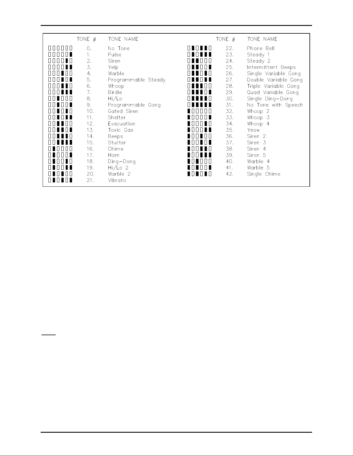
TONE SELECTION
You can select the desired tone for each of the seven inputs from an internal library of 42 tones. Figure 1
gives the tone names and their corresponding LED pattern. You should sample the tones as explained in
step 4 below.
Keep in mind that input 1 is the highest priority, and input 7 is the lowest. For example, if input 6 is
sounding when input 2 is activated, input 2 will interrupt. After input 2 is deactivated, or times out, tone 6
will sound again, starting from the beginning of its time duration. In this way, lower priority
announcements are not lost.
1. Set S1 to OOOC.
2. Press the programming switch of the tone that you want to program (1 to 7). The corresponding LED
will light to verify your selection.
3. Press SW8. LEDs 2 through 7 will display a pattern. See Figure 1 to identify the tone that is presently
selected.
4. Use the following switches to change tones, if desired:
• Switch 1: advances the tone number by 1
• Switch 2: advances the tone number by 10
• Switch 3: clears the tone number to 0
• Switch 4: enables the programmer to hear the tone through the speaker. Press Switch 4 a second
time to turn the tone off. If you cannot hear the tones, the volume control (potentiometer R25) may
need to be turned up. It is located to the right of S1 on the inside front cover.
\\s_eng\gtcproddocs\standard ioms - current release\42004 instr. manuals\42004-278a.doc
12/97
Page 5
Page: 5 of 21
Model TS959 Tone/Speech Generator Pub. 42004-278A
Figure 1. Tone Selection Library
1. When the desired tone is identified, press SW8 to store the tone selection. The LEDs will flash
through 3 sweeps indicating that the unit has accepted the new parameters and is storing them in
memory.
2. If only one input is to be changed, proceed to step 7. If additional tones must be changed, repeat
steps 2 through 5 until all new tones have been programmed, and then proceed to step 7.
3. Reset S1 to OOOO.
SIGNAL DURATION
This step need only be completed for tones selected to have momentary activation. See the Activation
section. Tones programmed for maintained activation will continue as long as the corresponding alarm
input switch is activated. If the duration of momentary activation inputs is not programmed, the unit will
default to continuous operation. In the continuous mode, the alarm will remain “latched” after activation
until the reset switch on the front panel or an external reset switch (N.O.) connected between TB2-18 and
common (TB2-22, TB2-24, or TB2-26) is closed.
Note: Activating the reset input will clear ALL alarm activations.
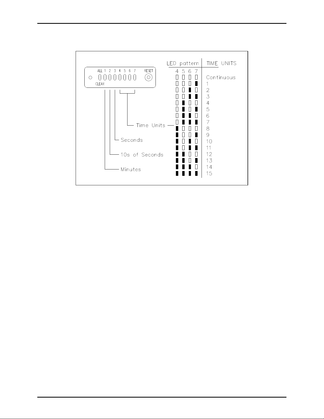
The programmed time duration of an input can be determined by observing the front panel LEDs and
comparing them to Figure 2. LEDs 1, 2, and 3 represent the units of time: minutes, increments of 10
seconds, and single seconds, respectively. LEDs 4, 5, 6, and 7 represent the number (quantity) of the units
described by LEDs 1, 2, and 3.
A timed duration activation of between 1 second and 15 minutes can be programmed for each of the seven
alarm inputs. The front panel LEDs will again be used to indicate program status.
1. Set S1 to CCCO.
2. Press the switch of the input that you want to program (1 to 7). The corresponding LED lights to
verify your selection.
\\s_eng\gtcproddocs\standard ioms - current release\42004 instr. manuals\42004-278a.doc
12/97
Page 6
Page: 6 of 21
Model TS959 Tone/Speech Generator Pub. 42004-278A
3. Press SW8 to determine the present duration status. To interpret the number, see Figure 2. For
example, if LEDs 5 and 6 are lit, the duration is 6 units.
Figure 2. Signal Duration Settings
1. If the duration must be changed, press switch 1, 2, or 3 to select the time unit to be changed.
• Switch 1: minutes (for durations of 1 to 15 min.)
• Switch 2: increments of 10 seconds (for durations of 10 seconds to 150 seconds)
• Switch 3: seconds (for durations of 1 to 15 seconds)
2. Now press switch 4, 5, or 6 to get the appropriate number of time units.
• Switch 4: advances the time units by 1
• Switch 5: advances the time units by 10
• Switch 6: resets the units to continuous duration
3. When the LEDs reflect the desired duration, press SW8 to store the data. The LEDs will flash
through 3 sweeps indicating that the unit has accepted the new parameters and is storing them in
memory.
4. If only one input is to be changed, proceed to step 8. If additional input time durations must be
changed, repeat steps 2 through 6 until all inputs have been programmed, and then proceed to step 8.
5. Reset S1 to OOOO.
\\s_eng\gtcproddocs\standard ioms - current release\42004 instr. manuals\42004-278a.doc
12/97
Page 7
Page: 7 of 21
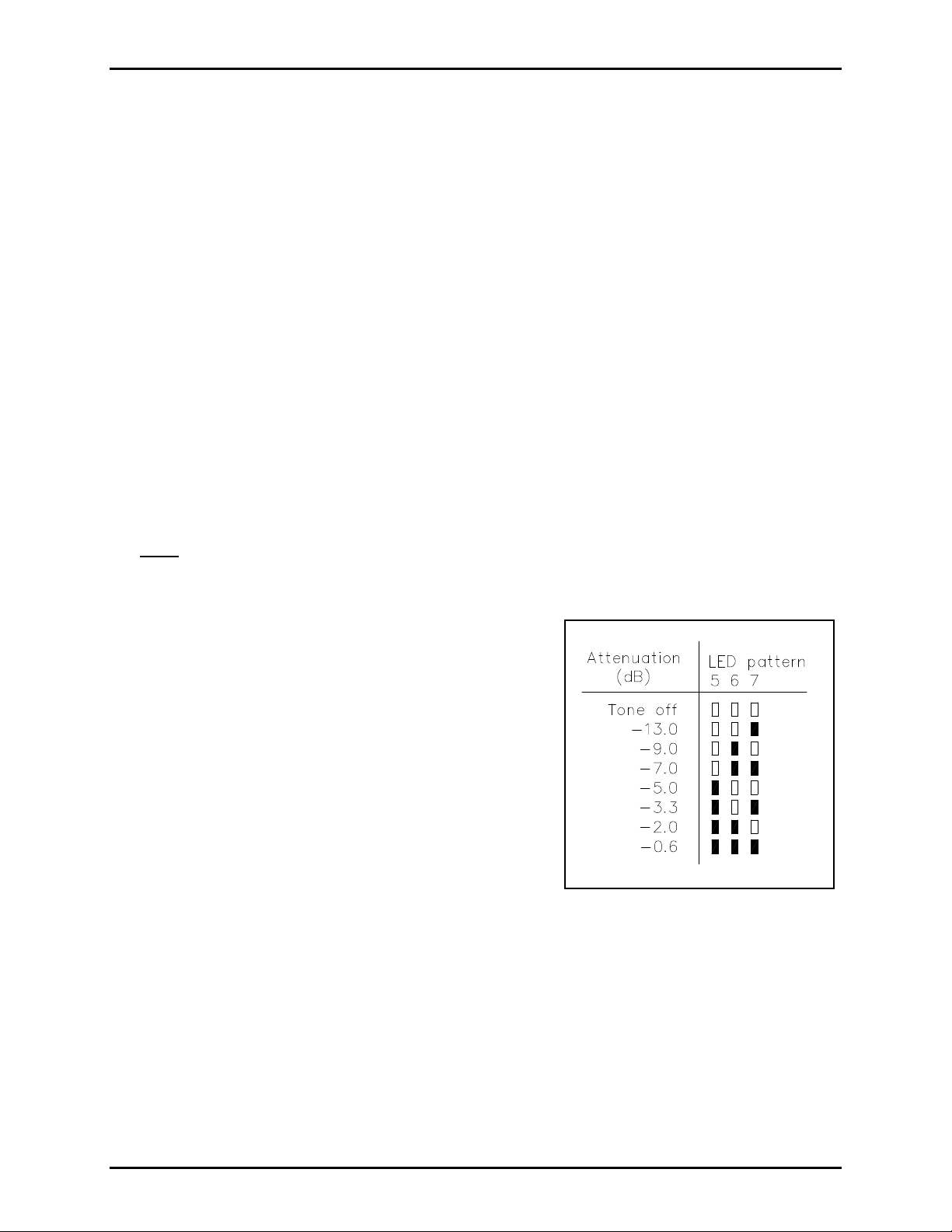
Figure 3. Mute Attenuation
Model TS959 Tone/Speech Generator Pub. 42004-278A
MUTE ATTENUATION AND DURATION
The mute function lowers the sound volume of alarm tones and suspends speech messages. It can be
programmed to activate for a maximum of 75 seconds for a single contact closure. This prevents
emergency tones from being muted for too long. The mute function is active until either the contact closure
is removed or the programmed mute duration elapses. You may resume page override by reactivating the
contact closure which resets the mute duration time.
You may also choose “No Time-out” for the mute duration. This setting allows muting of alarm tones and
suspension of speech messages for an unlimited length of time.
The mute feature serves two functions:
1. Automatic Mute: The sound volume of generated tones is automatically reduced during each speech
message. The amount of reduction is the programmed amount for mute attenuation. The tones return
to full volume between speech messages.
2. Manual Mute: When the mute input is activated, the sound volume of tones is reduced by a
programmed amount, and pre-recorded speech messages are suspended temporarily after the inprogress message is completed. Speech messages will resume from the beginning of the message when
the mute input is deactivated. During live voice pages, tones are audible just as they are during speech
messages. This feature ensures that voice pages are heard clearly over tones and that speech messages
do not interfere with voice pages.
Note: Activation of the mute input feature is accomplished by providing a contact closure on the tone
generator’s mute input.
Additional equipment is required for Page/Party® stations to
activate the mute feature (page override). The provision for
this option is included in Centra-Page stations, and no
additional equipment is required.
The Mute attenuation function sets the muted sound volume
level for tones during the broadcast of programmed speech
messages or live voice pages. The factory default setting is
-7.0 dB. The setting can be changed as described in the
programming instructions that follow.
Eight different attenuation values are available. See Figure 3
to interpret the LED pattern corresponding to the attenuation
levels.
The value programmed for mute duration is assigned to all
tones. A contact closure between TB2-20 and common (TB2-22, -24, or -26) activates the mute function.
The default setting for mute duration is “No Time-out.” Voice pages are then made “over” the alarm tones
and speech messages.
Voice page function requires additional equipment. Consult GAI-Tronics for additional information.
\\s_eng\gtcproddocs\standard ioms - current release\42004 instr. manuals\42004-278a.doc
12/97
Page 8

Page: 8 of 21
Model TS959 Tone/Speech Generator Pub. 42004-278A
MUTE ATTENUATION AND DURATION PROGRAMMING INSTRUCTIONS
1. Set S1 to CCOC. Indicator LEDs 4 through 7 light in a pattern to designate the current mute duration
time. See Figure 4 to interpret the LED pattern.
Figure 4. Mute Duration
1. If the duration time needs to be changed, press the appropriate program switches:
• Switch 1: advances the time in 5 second intervals
• Switch 2: advances the time in 50 second intervals
Note: The mute duration advances to the maximum value, and then cycle back to zero and begins to
advance again.
3. After setting the mute duration, press SW8 once to program the mute attenuation. LEDs 5 through 7
will now show the current attenuation level. See Figure 3 to interpret the LED pattern.
4. To change the attenuation, press programming Switch 3 to advance the attenuation setting.
Note: The attenuation will advance to maximum, and then cycle back to zero and begins to advance
again.
5. Press SW8 to save the information. The LEDs will flash through 3 sweeps indicating that the unit has
accepted the new parameters and is storing them in memory.
6. Reset S1 to OOOO.
Note: If a mute switch fails, either through a short between contacts or a short on the mute switch
interconnect cable, the maximum length of time muting will occur is limited to the time programmed (5 to
75 seconds). However, if “No Time-out” is selected for the mute duration, the muting will remain active
until the short is removed.
\\s_eng\gtcproddocs\standard ioms - current release\42004 instr. manuals\42004-278a.doc
12/97
Page 9

Page: 9 of 21
Model TS959 Tone/Speech Generator Pub. 42004-278A
SPECIFIC TONE FREQUENCIES
The frequency of the Programmable Steady tone (tone 5) and the gong tones (tones 9, 26, 27, 28, and 29)
can be programmed to a selected frequency. If these tones are not being used, skip this procedure. The
frequencies of the Programmable Steady tone and the gong tones are factory-set to 800 Hz (default status).
Programmable Steady Tone Frequency
1. Set S1 to OCCO. The front panel LEDs will indicate the
current status. Refer to Figure 5 to interpret LED pattern.
2. Push the switches until the correct LED pattern is
displayed.
• Switch 1: advances the number by 100 Hz
• Switch 2: advances the number by 1000 Hz
Note: The tone frequency will advance to maximum and
then cycle back around.
3. Press SW8 to save the entry. The LEDs will flash
through 3 sweeps indicating that the unit has accepted the
new parameters and is storing them in memory.
4. Reset S1 to OOOO.
Gong Tone Frequency
1. Set S1 to COCO.
2. Repeat Steps 2 through 4 of the Programmable Steady
Figure 5. Frequency Settings
Tone Frequency section.
Note: All gong tones are programmed to the same frequency. Different gong tones cannot be programmed
to different frequencies.
VOLUME LEVEL CONTROL
Note: The VLC option is used only in conjunction with GAI-Tronics speaker amplifiers equipped with a
VLC receiver. If the VLC option is not used, skip this step.
The VLC option is used to raise or lower the volume of pre-selected alarms or tones in particular areas.
For example, a facility located in a residential area may want to lower the level of its outdoor speakers at
night. VLC lowers the tone volume of selected speakers while broadcasting at full volume elsewhere.
When the VLC option is activated on the TS959, an inaudible (50 kHz) signal is placed on the page line
during an alarm condition. This signal is used to activate the VLC receivers in the amplifiers on the page
line. The VLC receivers then set the amplifier gain to a preset value bypassing the normal volume control.
1. Set S1 to CCOO.
2. All input switches (alarm tones) activating the VLC signal are indicated by the front panel LEDs. If
the LED indicator for an input is on, the VLC signal will be transmitted when that alarm is activated.
Pressing the corresponding input switch toggles the function on and off.
3. When all 7 inputs are set as desired, press SW8 to save the data. The LEDs will flash through 3
sweeps, indicating that the unit has accepted the new parameters and is storing them in memory.
4. Reset S1 to OOOO.
\\s_eng\gtcproddocs\standard ioms - current release\42004 instr. manuals\42004-278a.doc
12/97
Page 10

Page: 10 of 21
Model TS959 Tone/Speech Generator Pub. 42004-278A
SPEECH REPEAT OPTION
Note: Perform this procedure only if the optional speech board was purchased for use with the TS959.
With the Speech Repeat option, you may choose to either have the speech message play only once or
continually repeat. If the repeat option is selected, the message plays continually until the signal duration
time ends, until the alarm is physically reset, or until the activation ceases. The signal duration time is set
according to instructions in the Signal Duration section on page 5. The Speech Repeat option can be
programmed individually for each input.
1. Set S1 to OOCO.
2. Front panel LEDs indicate the present status. Lit LEDs designate a single message, while unlit LEDs
designate repeated messages. Press the corresponding switch until the LEDs reflect the desired
settings.
3. Press SW8 to save the configuration. The LEDs will flash through 3 sweeps, indicating that the unit
has accepted the new parameters and is storing them in memory.
4. Reset S1 to OOOO.
SPEECH INTER-MESSAGE PAUSE (SPEECH REPEAT INTERVAL)
Note: Perform this procedure only if the optional speech board was purchased for use with the TS959.
If a message is programmed to repeat as described in the Speech Repeat section, the TS959 can be
programmed to pause for a predetermined time between repeated voice announcements. If an alarm tone is
sounded in conjunction with a voice message, the tone will be muted during the voice message, and return
to full volume during the inter-message pause interval.
1. Set S1 to OCOC. Front panel LEDs
display the period of inter-message
pause. This pause is the same for all 7
inputs. See Figure 6 to interpret the
inter-message pause time.
2. To change the duration, press switches
1, 2, or 3 to select the time unit to be
changed:
• Switch 1: minutes
• Switch 2: increments of 10 seconds
• Switch 3: seconds
3. Press switches 4, 5, or 6 to get the
appropriate number of time units.
• Switch 4: advances the units by 1
Figure 6. Inter-message Pause
• Switch 5: advances the units by 10
• Switch 6: resets the TS959 to no inter-message pause; 0 seconds between messages
4. Press SW8 to store the duration selection. The LEDs will flash through 3 sweeps indicating that the
unit has accepted the new parameters and is storing them in memory.
5. Reset S1 to OOOO.
\\s_eng\gtcproddocs\standard ioms - current release\42004 instr. manuals\42004-278a.doc
12/97
Page 11

Page: 11 of 21
Model TS959 Tone/Speech Generator Pub. 42004-278A
PRE-ANNOUNCEMENT TONE
Note: Perform this procedure only if the optional speech board was purchased for use with the TS959.
The pre-announcement tone is used as an attention-getting device before a speech message begins. The
tone will always be the same as the tone of the particular input activated. For example, if input 4 uses the
Warble tone, the pre-announcement tone will also be the Warble tone. The only exception to this rule is
tone 31, No Tone With Speech. In this case, the tone that will sound is tone 5, the Programmable Steady
tone, which cannot be changed.
You can program the pre-announcement tone for activation/deactivation and program the duration of the
pre-announcement tone. The duration and activation/deactivation will be the same for all inputs.
Activation/Deactivation of Pre-announcement Tone
1. Set S1 to OCCC.
2. Front panel LEDs indicate the current status. If LED 1 is lit, the tone is activated. If LED 1 is not lit,
the tone is not activated.
3. You can toggle the selection by pressing switch 1. LED 1 should then light or extinguish to reflect
your choice.
4. Press SW8 to save the information. The LEDs will flash through 3 sweeps indicating that the unit has
accepted the new parameters and is storing them in memory.
5. Reset S1 to OOOO.
Duration of Pre-announcement Tone
The duration of the pre-announcement tone is not independently programmable. The duration is determined
by the information programmed in the Speech Inter-message Pause option. The speech inter-message
pause can last from zero seconds to 15 minutes. The duration of the pre-announcement tone is from zero to
ten seconds. If the speech inter-message pause is between zero and ten seconds, then that will be the exact
duration of the pre-announcement tone. If, however, the speech inter-message pause is 11 seconds or more,
the pre-announcement tone duration will remain ten seconds.
REQUIRED POST-PROGRAMMING
The following steps must be completed after the enclosure is mounted and the system connections have
been made to the enclosure. If necessary, see the Installation section on page 14 for mounting and wiring
the enclosure before proceeding.
1. Disconnect power.
2. Disconnect any temporary programming switches.
3. Connect the permanent, operational activation switches to the TS959. See Figure 11. The actual
activation switch type (N.O. or N.C.) must be now programmed again by performing steps 4 to 7
below. This ensures that the tone generator has the switch type information for the permanent
activation switches in memory.
4. Reconnect power.
5. Set S1 to COOO.
6. Press SW8. The front panel LEDs will flash through 3 sweeps indicating that the unit has determined
switch types, accepted the new parameters and is storing them in memory.
\\s_eng\gtcproddocs\standard ioms - current release\42004 instr. manuals\42004-278a.doc
12/97
Page 12

Page: 12 of 21
Model TS959 Tone/Speech Generator Pub. 42004-278A
7. Reset S1 to OOOO.
8. Remove the temporary speaker attached to the audio out terminals, and reconnect the audio out
terminals to the system. See Figure 12.
VOLUME ADJUSTMENTS
The potentiometer labeled R25 on the inside front cover in the upper right corner adjusts the output level of
the tones. See Figure 7. Test a number of tones, and sample the output level at various locations to ensure
that this adjustment is correct. Adjust as necessary.
If the TS959 was purchased with the optional speech board, there is a separate volume control adjustment
for the speech volume only, potentiometer R7. This adjustment is located on the front panel assembly on
the optional speech printed circuit card.
Figure 7. Simplified Detail of TS959 PC Board(s)
REPROGRAMMING
If any of the preceding options need to be reprogrammed at any time, follow the steps outlined in the
application sections. Remember to perform the required Post Programming procedure after making any
programming changes.
If the speech board needs to be reprogrammed, consult the factory.
\\s_eng\gtcproddocs\standard ioms - current release\42004 instr. manuals\42004-278a.doc
12/97
Page 13

Page: 13 of 21
Model TS959 Tone/Speech Generator Pub. 42004-278A
PROGRAMMING SUMMARY CHART
DIP
Switches Program Mode
Factory
Settings User Programming
CCCC Default Reset COOO Switch Type Normally Open
OCOO Activation Momentary
OOOC Tone Selection:
Input 1
Input 2
Input 3
Input 4
Input 5
Input 6
Input 7
Pulse, #1
Siren, #2
Yelp, #3
Warble, #4
Steady, #5
Gated Siren, #10
Hi Lo, #8
CCCO Signal Duration:
Input 1
Input 2
Input 3
Input 4
Input 5
Input 6
Input 7
CCOC Mute Duration
Mute Attenuation
No Time-out
No Time-out
No Time-out
No Time-out
No Time-out
No Time-out
No Time-out
No Time-out
-7.0 dB
OCCO
COCO
Programmable Steady Frequency
Gong Frequency
800 Hz
800 Hz
CCOO Volume Level Control Off
*OOCO Speech Repeat:
Message 1
Message 2
Message 3
Message 4
Message 5
Message 6
Message 7
Repeat
Repeat
Repeat
Repeat
Repeat
Repeat
Repeat
*OCOC Speech Inter-message Pause 2 seconds
*OCCC Pre-announcement Tone:
Tone 1
Tone 2
Tone 3
Tone 4
Tone 5
Tone 6
Tone 7
2 seconds
2 seconds
2 seconds
2 seconds
2 seconds
2 seconds
2 seconds
*This option applies only if the TS959 is supplied with an optional speech board assembly.
\\s_eng\gtcproddocs\standard ioms - current release\42004 instr. manuals\42004-278a.doc
12/97
Page 14

Page: 14 of 21
Model TS959 Tone/Speech Generator Pub. 42004-278A
Installation
WARNING
This device can present a 115-230 V ac shock hazard. Please use care when handling this device. Be
sure that the ac/dc power is not connected during wiring.
Install the TS959 in an area with a temperature range of +32ºF to +122ºF (0ºC to +50ºC) and away from
equipment that could cause excessive electrostatic or electromagnetic interference or generate high voltages.
The remote activation, reset, and muting switches can be located up to one mile from the TS959. Use
shielded cable if the interconnect cable is exposed to either high-intensity RF (radio frequency) or
electrostatic fields.
MOUNTING
1. Loosen the 4 outer captive screws, and swing the front panel open to the left. Carefully remove the
ribbon cable by pushing down on lower tab and pushing up on upper tab. Then, pull ribbon cable
outward. Remove the front panel by pulling the hinges out of the holes in the rear enclosure.
2. Determine which of the 4 available conduit locations is to be used. Remove the PCBAs until the
conduit installation is complete. Drill spots have been provided for use with either a chassis punch or
hole saw for hole sizes between 1-43/64 and 1-3/4 inches. See Figure 8 for the drill spot locations.
Figure 8. Mounting Details
\\s_eng\gtcproddocs\standard ioms - current release\42004 instr. manuals\42004-278a.doc
12/97
Page 15

Page: 15 of 21
Model TS959 Tone/Speech Generator Pub. 42004-278A
3. See Figure 9 for the location of the 4 mounting holes. Each hole is 0.280-inch in diameter. Install the
rear enclosure on the wall with screws.
Figure 9. Mounting Details
4. Use Myers ST-4 (1-1/4 inches) Scru-Tite hubs or equivalent. See Figure 9 for the conduit hub
connections. Reducers must be used for smaller conduit sizes in order to not inhibit the proper contact
with the supplied grounding plates. Hub(s) must be connected to the conduit before being connected to
the enclosure. Run the wires through the conduit to connect the power and signal lines to the proper
terminals as specified in the Wiring section. Hubs must be installed as recommended by the hub
manufacturer to ensure proper contact to the grounding plate.
WIRING
CAUTION
Do not apply power until all the connections have been wired.
\\s_eng\gtcproddocs\standard ioms - current release\42004 instr. manuals\42004-278a.doc
12/97
Page 16

Page: 16 of 21
Model TS959 Tone/Speech Generator Pub. 42004-278A
Power
Note: The unit can be powered by either a 115 V ac or a 24 V dc power supply. Use only one power
source, either 115 V ac or 24 V dc, at a time.
The ac power connection is made to terminals TB1-1 and TB1-2 as shown in Figure 10. For 24 V dc
operation, place the +24 V dc on TB1-4 and the common on TB1-3. Connect the earth ground wire to the
grounding terminal lug provided inside the enclosure at the top.
Activation Inputs
The activation input switches/relay contacts will be
programmed for either momentary or maintained,
normally open (N.O.) or normally closed (N.C.).
These switches may be installed up to one mile away
from the TS959 using 24 AWG wire or larger.
The switches may be any combination of momentary
switches, maintained switches, or relay contacts, either
N.O. or N.C. The contacts should be rated for 15 V,
5 mA.
The switches should be wired according to Figure 11.
Figure 10. Wiring Details
For each switch, connect one switch terminal to the corresponding input terminal (TB2 terminals) and the
other switch terminal to one of the common terminals (TB2-16, -22, -24 and -26).
Figure 11. Typical Wiring Configuration
\\s_eng\gtcproddocs\standard ioms - current release\42004 instr. manuals\42004-278a.doc
12/97
Page 17

Page: 17 of 21
Model TS959 Tone/Speech Generator Pub. 42004-278A
Reset (Used as a Remote)
The reset terminal (TB2-18) will override and abort any activity in progress. A user-supplied, remote,
momentary, normally open (N.O.) switch contact closure must be connected from TB2-18 to one of the
common terminals (TB2-16, -22, -24 and -26). Use 24 AWG or larger wire for distances up to one mile.
Muting Activation Input
A normally open (N.O.), momentary contact connected between TB2-20 and common (TB2-16, -22, -24 or
-26) can be used to activate the mute function. See the Mute Attenuation and Duration section for the
details of the mute operation. The mute switch can be located up to one mile away from the TS959 if
24 AWG or larger wire is used.
Audio Output Connections
Balanced audio output connections
are provided to drive either the
33-ohm GAI-Tronics page line or a
600-ohm system. The page line
output is a current source that must
be terminated with a 33-ohm load for
proper operation (GAI-Tronics Line
Balance Assembly provides the
proper termination impedance). The
600-ohm output is voltage-driven
with a source impedance of
600 ohms.
Figure 12. Audio Output Connections
When the 33-ohm (page line output) is desired, connect the wires to TB2-25 and -27 as shown in
Figure 12. When using the 600-ohm output, connect the wires to TB2-23 and -27, and connect a jumper
wire between TB2-29 and -27.
Auxiliary Outputs
The TS959 is supplied with nine auxiliary output connections which are designed to drive externally
mounted relays. Nine MOS FET transistors are configured to sink up to 100 mA maximum to circuit
common. When operating the TS959 from 115 V ac, the internal supply can supply up to 900 mA of
unregulated +24 V dc current to external relays using TB2-28 or TB1-4. An external supply can also be
used. When using a +24 V dc source to operate the TS959, external relays should be powered directly
from the external power supply (do not use TB2 pin 28 to provide power to the relays). See Figure 13 for
wiring information.
TB2-3
TB2-5
TB2-7
Aux. Output 1
Aux. Output 2
Aux. Output 3
TB2-9
TB2-11
TB2-13
Aux. Output 4
Aux. Output 5
Aux. Output 6
TB2-15
TB2-17
TB2-21
Aux. Output 7
All clear output
VLC control/Any Alarm Activated
(See Note)
Note: VLC Control must be programmed. See the Volume Level Control section.
An auxiliary output will be approximately +24 V when the input is inactive. The output will be
approximately +0.5 V when its input is active. The all-clear output is active when there are no inputs
active. This output will go to inactive when any of the seven inputs becomes active.
\\s_eng\gtcproddocs\standard ioms - current release\42004 instr. manuals\42004-278a.doc
12/97
Page 18

Page: 18 of 21
Model TS959 Tone/Speech Generator Pub. 42004-278A
Figure 13. Auxiliary Outputs
Seven of the auxiliary output connections correspond to the alarm-indicating LEDs on the front panel and
are activated when an alarm is received. These outputs and LED indicators will reflect all the alarms that
have been received, even though only the highest priority alarm will sound. Outputs are also provided to
reflect all-clear and VLC activation. See the Volume Level Control section for the details of VLC
operation).
All the outputs are designed to be active low (transistor switch closed to common) when activated. The
following list describes the operation of the auxiliary output connections.
Aux. Output No. Switch closed to common when
1 TB2-3 Alarm 1 (highest priority) activated
2 TB2-5 Alarm 2 activated
3 TB2-7 Alarm 3 activated
4 TB2-9 Alarm 4 activated
5 TB2-11 Alarm 5 activated
6 TB2-13 Alarm 6 activated
7 TB2-15 Alarm 7 (lowest priority) activated
8 TB2-17 No alarms are activated
9 TB2-21 VLC Control/Any alarm is activated (See Note)
Note: VLC Control must be programmed. See the Volume Level Control Section.
\\s_eng\gtcproddocs\standard ioms - current release\42004 instr. manuals\42004-278a.doc
12/97
Page 19

Page: 19 of 21
Model TS959 Tone/Speech Generator Pub. 42004-278A
Final Assembly and Adjustment
The tone volume control (R25) for the alarm tones is located in the upper right corner of the front cover.
Check the level of the signal at various locations after the adjustment is made.
If the TS959 is supplied with an optional speech board, a separate speech volume control, labeled
SPEECH VOLUME is available. This adjustment is located on the left center of the front panel assembly.
See Figure 7 for details.
When all programming and adjustments are complete, disconnect power cable. Plug the TS959 tone
generator into the enclosure. Secure it with the four screws provided, one in each corner. Complete the
Installation procedure by reapplying power to the unit.
Specifications
Power Requirements.........................................................................................90-132 V ac, 0.4 amp max.
18-26 V dc, 0.4 amp max.
Speech Capacity ............................................................................................................. up to 64 seconds;
20 words = 32 sec. max.
40 words = 48 sec. max.
80 words = 64 sec. max.
Output Level ........................................................................Adjustable 1.5 V
750 mV
Contact Requirements .........................................................................................Maintained or momentary
normally open or normally closed, SPST, 5 mA, 15 V
Auxiliary Outputs............................................................sink 100 mA max. per output to circuit common
Muting.................................................................................................... -0.6 to -13.0 dB (programmable)
Muting Time Limit................................................................................................................... 75 seconds
Enclosure.............................................................................. High-impact, glass-reinforced polyester, gray
Mounting...........................................................................Wall mounting; four 0.280-inch mounting holes
Connections......................................................................... Four drill spots for location of conduit fittings
max. into a 33-ohm load;
RMS
max. to a 600-ohm load
RMS
Dimensions......................................................... 9.52 H × 8.02 W × 3.82 D inches ( 241 × 201 × 97 mm)
Temperature Range............................................................................ +32º F to +122º F (0º C to +50º C)
Weight............................................................................................................................... 5 lbs. (2.27 kg)
Approval...................................................................... Complies with FCC Part 15, Subpart J for Class A
computing devices
Fuses.............................................................................................................0.4A Slow-Blow, 5 × 20 mm
\\s_eng\gtcproddocs\standard ioms - current release\42004 instr. manuals\42004-278a.doc
12/97
Page 20

Page: 20 of 21
Model TS959 Tone/Speech Generator Pub. 42004-278A
ELECTRICAL RATING OF INPUTS AND OUTPUTS
Termination Signal Name Voltage Range Current
Power Requirements
TB1-1 ac hot 90-132 V ac .4 amp max.
TB1-2 ac neutral
Note: Only one power source must be used with this unit—either 115 V ac or +24 V dc.
TB1-3 dc common
TB1-4 +24 V dc 18-26 V dc .4 amp max.
Input Signals
TB2-2 Input 1 Dry Contact 5 mA max.
TB2-4 Input 2 Dry Contact 5 mA max.
TB2-6 Input 3 Dry Contact 5 mA max.
TB2-8 Input 4 Dry Contact 5 mA max.
TB2-10 Input 5 Dry Contact 5 mA max.
TB2-12 Input 6 Dry Contact 5 mA max.
TB2-14 Input 7 Dry Contact 5 mA max.
TB2-18 Reset Input Dry Contact 5 mA max.
TB2-20 Mute Input Dry Contact 5 mA max.
TB2-30 Mode Input Dry Contact 5 mA max.
*TB2-19 LED +V Input +18 to +26 V dc 150 mA max.
Output Signals
TB2-3 Aux Out 1 +24 V dc Sink 100 mA max.
TB2-5 Aux Out 2 +24 V dc Sink 100 mA max.
TB2-7 Aux Out 3 +24 V dc Sink 100 mA max.
TB2-9 Aux Out 4 +24 V dc Sink 100 mA max.
TB2-11 Aux Out 5 +24 V dc Sink 100 mA max.
TB2-13 Aux Out 6 +24 V dc Sink 100 mA max.
TB2-15 Aux Out 7 +24 V dc Sink 100 mA max.
TB2-17 All Clear Out +24 V dc Sink 100 mA max.
TB2-21 VLC/Active Alarm +24 V dc Sink 100 mA max.
TB2-23 Audio 600-ohm 0.775 V
TB2-25 Audio 33-ohm 1.5 V
RMS
RMS
1.3 mA
45 mA
TB2-27 Audio common
TB2-28 +24 V dc output +18 to +26V dc 900 mA max. (using ac power source) or,
100 mA max. (using 24 V dc power source)
TB2-29 600-ohm option
*Using an external power source to power the front panel LEDs requires the removal of jumper W1.
\\s_eng\gtcproddocs\standard ioms - current release\42004 instr. manuals\42004-278a.doc
12/97
Page 21

Page: 21 of 21
Model TS959 Tone/Speech Generator Pub. 42004-278A
Available DC Returns
TB2-1 dc common
TB2-16 dc common
TB2-22 dc common
TB2-24 dc common
TB2-26 dc common
REPLACEMENT PARTS
Replacement parts are available through GAI-Tronics. Please use number when ordering.
Part No. Description
12513-003 Hinge Kit
12520-002 PCBA Switch Assembly Kit
12560-002 Power Supply Kit (115 V ac)
51809-015 Fuse, 0.4A Slow-Blow, 5 x 20 mm
69105-004 Termination Board PCBA
ACCESSORIES
Part No. Description
12250-001 VLC Receiver Kit for 600 or 700 Series Speaker Amplifier
12605-001 115 V ac to 230 V ac Upgrade Kit
\\s_eng\gtcproddocs\standard ioms - current release\42004 instr. manuals\42004-278a.doc
12/97
Page 22

Warranty
Equipment. GAI-Tronics warrants for a period of one (1) year from the date of shipment, that any
GAI-Tronics equipment supplied hereunder shall be free of defects in material and workmanship, shall
comply with the then-current product specifications and product literature, and if applicable, shall be fit
for the purpose specified in the agreed upon quotation or proposal document. If (a) Seller’s goods prove
to be defective in workmanship and/or material under normal and proper usage, or unfit for the purpose
specified and agreed upon, and (b) Buyer’s claim is made within the warranty period set forth above,
Buyer may return such goods to GAI-Tronics nearest depot repair facility, freight prepaid, at which time
they will be repaired or replaced, at Seller’s option, without charge to Buyer. Repair or replacement shall
be Buyer’s sole and exclusive remedy, and the warranty period on any repaired or replacement equipment
shall be one (1) year from the date the original equipment was shipped. In no event shall GAI-Tronics
warranty obligations with respect to equipment exceed 100% of the total cost of the equipment supplied
hereunder. Buyer may also be entitled to the manufacturer’s warranty on any third-party goods supplied
by GAI-Tronics hereunder. The applicability of any such third-party warranty will be determined by
GAI-Tronics.
Services. Any services GAI-Tronics provides hereunder, whether directly or through subcontractors,
shall be performed in accordance with the standard of care with which such services are normally
provided in the industry. If the services fail to meet the applicable industry standard, GAI-Tronics will,
for a period of one (1) year from the date of completion, re-perform such services at no cost to Buyer. Reperformance of services shall be Buyer’s sole and exclusive remedy, and in no event shall GAI-Tronics
warranty obligations with respect to services exceed 100% of the total cost of services provided
hereunder.
Warranty Periods. Every claim by Buyer alleging a defect in the goods and/or services provided
hereunder shall be deemed waived unless such claim is made in writing within the applicable warranty
periods as set forth above. Provided, however, that if the defect complained of is latent and not
discoverable within the above warranty periods, every claim arising on account of such latent defect shall
be deemed waived unless it is made in writing within a reasonable time after such latent defect is or
should have been discovered by Buyer.
Limitations / Exclusions. The warranties herein shall not apply to, and GAI-Tronics shall not be
responsible for, any damage to the goods or failure of the services supplied hereunder, to the extent
caused by Buyer’s neglect, failure to follow operational and maintenance procedures provided with the
equipment, or the use of technicians not specifically authorized by GAI-Tronics to maintain or service the
equipment. THE WARRANTIES AND REMEDIES CONTAINED HEREIN ARE IN LIEU OF AND
EXCLUDE ALL OTHER WARRANTIES AND REMEDIES, WHETHER EXPRESS OR IMPLIED
BY OPERATION OF LAW OR OTHERWISE, INCLUDING ANY WARRANTIES OF
MERCHANTABILITY OR FITNESS FOR A PARTICULAR PURPOSE.
Return Policy
If the equipment requires service, contact your Regional Service Center for a return authorization number
(RA#). Equipment should be shipped prepaid to GAI-Tronics with a return authorization number and a
purchase order number. If the equipment is under warranty, repairs or a replacement will be made in
accordance with the warranty policy set forth above. Please include a written explanation of all defects to
assist our technicians in their troubleshooting efforts.
Call 800-492-1212 (inside the USA) or 610-777-1374 (outside the USA) for help identifying the
Regional Service Center closest to you.
(Rev. 1/97)
 Loading...