

Page 1

Pub. 42004-420A
GAI-TRONICS® CORPORATION
A HUBBELL COMPANY
7325-101 Multi-Party Weatherproof
Aluminum 115 V AC Amplifier Enclosur e
Confidentiality Notice
This manua l is provide d sole ly as an operatio nal, installation, and ma inte nance guide and conta ins se nsitive
business and technical information that is confidential and proprietary to GAI-Tronics. GAI-Tronics retains
all intellectual property and other rights in or to the information contained herein, and such information may
only be us ed in connection with t he op erat ion of your GAI-T ronics pr oduct or system. This ma nual ma y
not b e discl osed i n any f orm, in whol e or in part, directly or indirectly, to any third party.
General Information
This manual applies to the GAI-Tronics 7325-101 Multi-Party Weatherproof Aluminum 115 V AC
Amplifier Enclosure, which is an important component of the 700 series Page/Party< system. This
enclosure is configured for multi-party systems and can accommodate conversations on up to five party
lines simult aneously.
The 7325-101 Enclosure is made of cast aluminum alloy, which is extremely weatherproof and corrosionresistant. This enclosure is equipped with terminal strips for connecting system cable. The 701 and 751
Series Amplifiers mate directly with this enclosure.
Installation
CAUTION
on the approval listing in the Specification section of this manual. Such installation may cause a
safety hazard and consequent injury or property damage.
When installing an add-on station, consult the system layout diagram at the end of this manual. This
figure, when used in conjunction with the station installation information and cable layout guide, should
provide all the information necessary to install additional Page/Party< stations.
Enclos ure Placement
All GAI-Tronics Page/Par t y® units are wired in parallel. Good system layout design minimizes the cable
required for each installation. GAI-Tronics multi-conductor cable, designed especially for this
application, is recommended. The number, size, and color-coding of conductors are listed in the
accompanying system connection diagram.
System layout and power cable length are very important when installing Page/Party< equipment.
Although it varies for different systems, the general guideline is that the total power cable length should
not exceed 1 mile (5280 feet) for 115 V ac systems. The total cable length is the most important
consideration while cable length between the stations is generally not a factor.
Do not install this equipment in hazardous areas other than those ind ic at e d
GAI-Tronics Corporation 400 E. Wyomissing Av e. Mohnton, PA 19540 USA
610-777-1374 800-492-1212 Fax: 610-796-5954
ISIT WWW.GAI-TRONICS.COM FOR PRODUCT LITERATURE AND MANUALS
V
Page 2
Pub. 42004-420A
7325-101 Multi- P ar ty Weatherproof Aluminum 115 V AC Amplifier Enclosure Page:
2 of 7
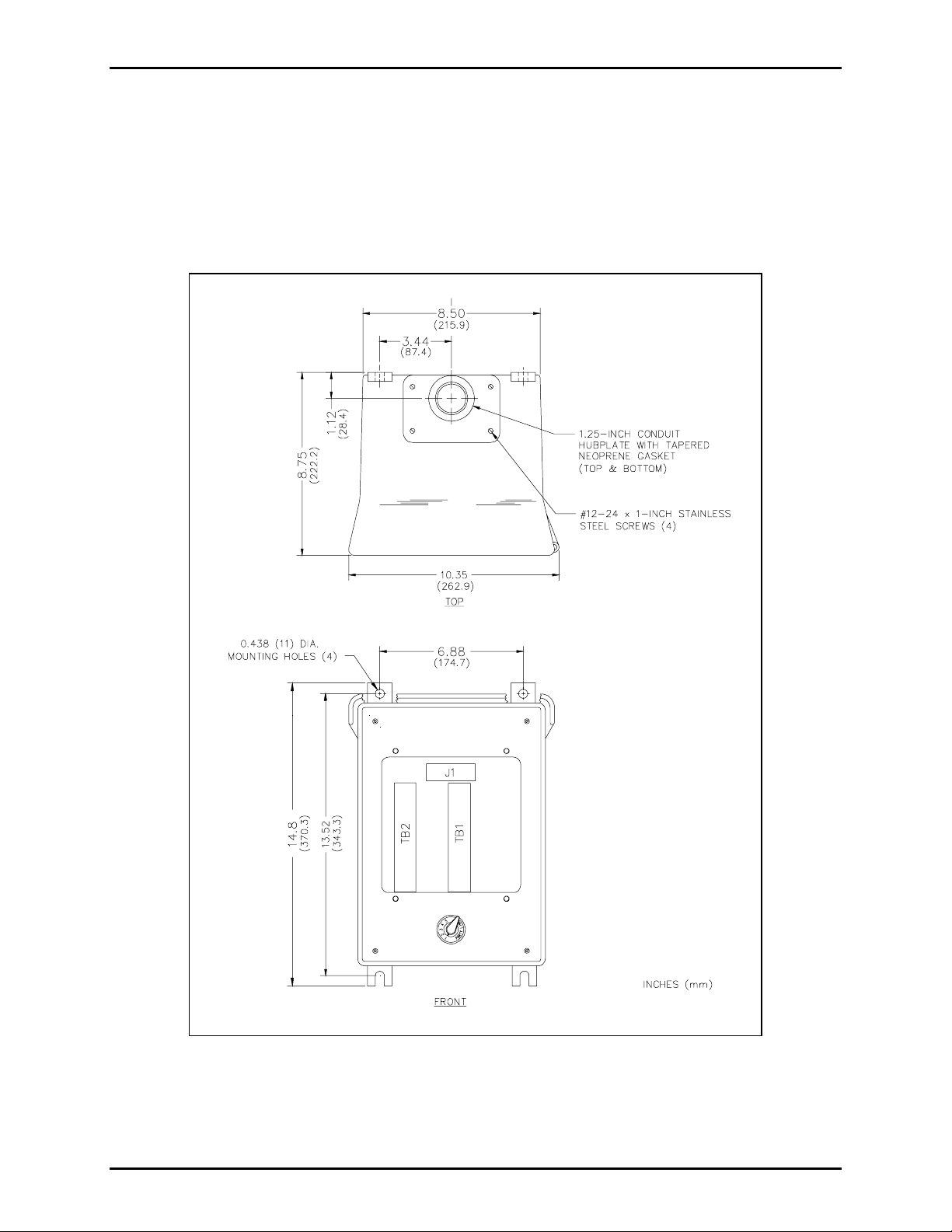
Mounting
The 7325-101 Enclosure is supplied with pre-drilled cable openings and conduit hubs with top and
bottom cap plugs in place to prevent contamination.
For specific details including mounting hole dimensions, refer to Figure 1. When mounting the
enclosure, use caution to avoid damaging the terminal blocks inside. The suggested mounting height for
all station enclosures is 54 inches (137 cm) up to the centerline of the enclosure.
Figure 1. 7325-101 Enclosure Mounting Details
f:\standard ioms - current releas e\ 42004 ins t r. manuals\42004-420a.doc
02/09
Page 3

Pub. 42004-420A
7325-101 Multi- P ar ty Weatherproof Aluminum 115 V AC Amplifier Enclosure Page:
3 of 7
Wiring
Attach the conduit to the enclosure. Feed the wiring through the conduit and bring it into the enclosure.
See Figure 2. Wire colors shown on the terminal block correspond to GAI-Tronics’ 60029 series multiparty system cable and 60028/60021 series speaker cable. The wires must be spade-lugged and connected
carefully and completely to the terminal block. An improper termination may result in diminished station
performance.
Local Muting
Figure 2 il lustrates local spea ker muting w hen statio ns are comp letely as semble d and p aging oper atio n
occu rs. Normally, when the s tat ion but ton is pressed, t he pag ing speaker connect e d to tha t sta tion is
silenced (muted) to prevent acoustic feedback to the handset microphone. However, while the handset is
in use for party line conversations, the paging speaker is “live” to enable paging calls from other stations.
To d i sa ble the m ut e featu re, follow these instr uct i ons:
1. Locate the lugged violet wire attached to terminal point 7 (mute) on the terminal block within the
enclosure.
2. Transfer the lugged violet wire to terminal point 8 (Page L1).
After any muting changes are made, unpack the station amplifier and install.
Mutual Muting
In the event that feedback occurs within an area and repositioning of the system speakers does not help,
mutual muting may be used to correct this problem.
Perform the following steps to mutually mute adjacent amplifiers/handsets within a zone.
1. Ensure that the purple lugged wire is connected to terminal 7 of TB1.
2. Connect terminal TB1-7 of the handset station to TB1-7 of the station within the zone that is causing
feedback. This is done by using the spare system wire (orange conductor) from within the system
cable that runs between the stations.
f:\standard ioms - current releas e\ 42004 ins t r. manuals\42004-420a.doc
02/09
Page 4

Pub. 42004-420A
7325-101 Multi- P ar ty Weatherproof Aluminum 115 V AC Amplifier Enclosure Page:
4 of 7
Figure 2. Wiring Diagram
f:\standard ioms - current releas e\ 42004 ins t r. manuals\42004-420a.doc
02/09
Page 5

Pub. 42004-420A
7325-101 Multi- P ar ty Weatherproof Aluminum 115 V AC Amplifier Enclosure Page:
5 of 7
Maintenance
Regular inspe c tion and a good pr e vent ive mainte nanc e program will i nc rease th e reliabil ity of your
GAI-Tronics s tat ion. The GAI-T ronics Field Ser v ice Department can formula te a service cont ract suited
to your facility’s specific need for preventive maintenance.
®
In addition, the following procedure can be used to keep Page/Party
systems opera ting effecti v el y.
WARNING
Before performing any of the following preventive maintenance steps, remove
all power fro m t he s tat ion.
1. Remove the amplifier from the enclosure.
2. Visu ally check the interior of the enclosure for signs of contam inat ion such as dust, cond e nsat ion or
liquid.
3. Using the No. 10440-002 Maintenance Cable, plug the amplifier into the connector in the enclosure.
Check, and if necessary, adjust the amplifier to maximize performance.
4. Reinstall the amplifier in the enclosure. Ensure that all gaskets and hardware are in place. Failure to
install the gaskets, which also act as spacers, can result in damage to the connectors on the amplifiers
and i nside the e nclos ur es and can cause s ystem f aults.
It may become necessary to re-terminate some or all of the enclosures in a system. If so, strip the wires
back to clean copper and connect only one wire to each connector to allow for easier future
troubleshooting.
Troubleshooting
The following table lists some hints to aid technicians in troubleshooting.
Problem Solution
Feedback occu rs
only during
page.
1. If a speaker is close to the statio n, try u sing th e mutin g feat ure in the amp lifi er
enclosure at the terminal blocks. Connect the violet wire at TB1-8 to TB1-7.
Refer to the wiring diagram.
2. Ensu re tha t speakers at tached to other stat ions locate d near by are not po inte d
in you r direction. If chan ging the orient atio n of th e other speakers has n o
effect, mutual muting may be required. Mutual muting silences all the
speakers within proximity to the affected stations during a page from any one
of the mutually muted stations.
Connect the orange wire (spare) to the TB1-7 of all the stations to be mutually
mut e d. N
OTE: If too many stations are selected, paging coverage can be
adversel y a ffected.
3. Check line terminations at the line balance assembly. Line balance assembly
connectio ns are critical.
Crosstalk
occurs.
One or more system cable pairs may be improperly terminated. Visually inspect
the syste m c abl e connec tions for acc idental crossing of the ca ble pairs or grou nds.
f:\standard ioms - current releas e\ 42004 ins t r. manuals\42004-420a.doc
02/09
Page 6

Pub. 42004-420A
7325-101 Multi- P ar ty Weatherproof Aluminum 115 V AC Amplifier Enclosure Page:
6 of 7
Specification s
Construction/Finish.................................................................Sand-cast aluminum alloy, cam-style latch,
hing ed do or wit h gas ket; gray baked enam e l
N
Mounting ................................................... Wall, column, or pole (mounting kit required for pole mount),
four 7/16-inch mounting holes
Connections .............................................................................Internal screw-type barrier terminal blocks
Dimensions ........................................................... 14.9 H × 10.8 W × 9.6 D inches (378 × 274 ×244 mm)
Shipping weight ............................................................................................................. 20.4 lbs. (9.3 kg)
Approvals.....................NRTL Listed for USA and Canada:..................Class I, Div. 2, Groups A, B, C, D
Class II, Div. 2, Groups F and G; Class III, Div. 2
Outdoor environmental rating:......................................................................................................Type 3R
Replacement Parts
OTE: Earlier enclosures could vary in color
Part No. Descrip tio n
10440-002 Maintenance Cable, 16-pin
12564-001 Party Line Selector Knob and Label Kit
12505-001 Door
12505-002 Door Handle
12566-001 Hub, 1.25 inches
25007-004 Closure/Plug (NPT 1.25 inches)
25203-002 Hub Gasket
25405-006 Ground Label
12609-001 Harness/Switch Assembly
12535-002 Hardware Kit (5 sets)
61509-004 Harness Assembly
f:\standard ioms - current releas e\ 42004 ins t r. manuals\42004-420a.doc
02/09
Page 7

Pub. 42004-420A
7325-101 Multi- P ar ty Weatherproof Aluminum 115 V AC Amplifier Enclosure Page:
7 of 7
f:\standard ioms - current releas e\ 42004 ins t r. manuals\42004-420a.doc
02/09
Page 8

Warranty
Equipment. GAI-Tronics warrants for a period of one (1) year from the date of shipment, that any
GAI-Tronics equipment supplied hereunder shall be free of defects in material and workmanship, shall
comply with the then-current product specifications and product literature, and if applicable, shall be fit
for the purpose specified in the agreed-upon quotation or proposal document. If (a) Seller’s goods prove
to be defective in workmanship and/or material under normal and proper usage, or unfit for the purpose
specified and agreed upon, and (b) Buyer’s claim is made within the warranty period set forth above,
Buyer may return such goods to GAI-Tronics’ nearest depot repair facility, freight prepaid, at which time
they will be repaired or replaced, at Seller’s option, without charge to Buyer. Repair or replacement shall
be Buyer’s sole and exclusive remedy. The warranty period on any repaired or replacement equipment
shall be the greater of the ninety (90) day repair warranty or one (1) year from the date the original
equipment was shipped. In no event shall GAI-Tronics warranty obligations with respect to equipment
exceed 100% of the total cost of the equipment supplied hereunder. Buyer may also be entitled to the
manufacturer’s warranty on any third-party goods supplied by GAI-Tronics hereunder. The applicability
of any such third-party warranty will be determined by GAI-Tronics.
Services. Any services GAI-Tronics provides hereunder, whether directly or through subcontractors,
shall be performed in accordance with the standard of care with which such services are normally
provided in the industry. If the services fail to meet the applicable industry standard, GAI-Tronics will
re-perform such services at no cost to buyer to correct said deficiency to Company's satisfaction provided
any and all issues are identified prior to the demobilization of the Contractor’s personnel from the work
site. Re-performance of services shall be Buyer’s sole and exclusive remedy, and in no event shall GAITronics warranty obligations with respect to services exceed 100% of the total cost of the services
provided hereunder.
Warranty Periods. Every claim by Buyer alleging a defect in the goods and/or services provided
hereunder shall be deemed waived unless such claim is made in writing within the applicable warranty
periods as set forth above. Provided, however, that if the defect complained of is latent and not
discoverable within the above warranty periods, every claim arising on account of such latent defect shall
be deemed waived unless it is made in writing within a reasonable time after such latent defect is or
should have been discovered by Buyer.
Limitations / Exclusions. The warranties herein shall not apply to, and GAI-Tronics shall not be
responsible for, any damage to the goods or failure of the services supplied hereunder, to the extent
caused by Buyer’s neglect, failure to follow operational and maintenance procedures provided with the
equipment, or the use of technicians not specifically authorized by GAI-Tronics to maintain or service the
equipment. THE WARRANTIES AND REMEDIES CONTAINED HEREIN ARE IN LIEU OF AND
EXCLUDE ALL OTHER WARRANTIES AND REMEDIES, WHETHER EXPRESS OR IMPLIED BY
OPERATION OF LAW OR OTHERWISE, INCLUDING ANY WARRANTIES OF
MERCHANTABILITY OR FITNESS FOR A PARTICULAR PURPOSE.
Return Policy
If the equipment requires service, contact your Regional Service Center for a return authorization number
(RA#). Equipment should be shipped prepaid to GAI-Tronics with a return authorization number and a
purchase order number. If the equipment is under warranty, repairs or a replacement will be made in
accordance with the warranty policy set forth above. Please include a written explanation of all defects to
assist our technicians in their troubleshooting efforts.
Call 800-492-1212 (inside the USA) or 610-777-1374 (outside the USA) for help identifying the
Regional Service Center closest to you.
(Rev. 10/06)
 Loading...