

Page 1
Pub. 42004-147G
GAI-TRONICS® CORPORATION
A HUBBELL COMPANY
Model 702-002, 732-102, and 733-002
24 V DC Single-Party Amplifier Enclosures
Confidentiality Notice
This manual is provided solely as an operational, installation, and maintenance guide and contains
sensitive business and technical information that is confidential and proprietary to GAI-Tronics.
GAI-Tronics retains all intellectual property and other rights in or to the information contained herein,
and such information may only be used in connection with the operation of your GAI-Tronics product or
system. This manual may not be disclosed in any form, in whole or in part, directly or indirectly, to any
third party.
General Information
The following GAI-Tronics amplifier enclosures are covered in this manual:
Model Description
702-002 Indoor Amplifier Enclosure; single-party, 24 V dc input
732-102 Weatherproof Aluminum Amplifier Enclosure, single-party, 24 V dc input
733-002 Weatherproof Non-metallic Amplifier Enclosure, single-party, 24 V dc input
The amplifier enclosure is an important component of the 700 Series Page/Party® system. The Model
702-002 Indoor Amplifier Enclosure is constructed of fabricated steel. The Model 732-102 Outdoor
Enclosure is made of cast aluminum alloy, and the Model 733-002 Outdoor Enclosure is made of Valox
Both outdoor enclosures are extremely weatherproof and corrosion-resistant.
These enclosures are equipped with terminal strips for connecting inter-station cable. The 701 and 751
Series amplifiers mate directly with these enclosures.
Installation
CAUTION
indicated on the approval listing in the “Specifications” section of this manual. Such installation
may cause a safety hazard and consequent injury or property damage.
When installing an add-on station, consult the 24 V dc system layout diagrams at the end of this manual.
These figures, when used in conjunction with the station installation information and cable layout guide,
should provide all the information necessary to install additional Page/Party< stations.
Do not install this equipment in hazardous areas or areas other than those
®
.
GAI-Tronics Corporation 400 E. Wyomissing Ave. Mohnton, PA 19540 USA
610-777-1374 800-492-1212 Fax: 610-796-5954
ISIT WWW.GAI-TRONICS.COM FOR PRODUCT LITERATURE AND MANUALS
V
Page 2

Pub. 42004-147G
Model 702-002, 732-102, and 733-002 24 V DC Single-Party Amplifier Enclosures Page: 2 of 12
In 24-volt systems, plan on several branch lines from the dc source with no more than six stations per
branch. One branch could span up to 4,000 feet for a single station. The Maximum Cable Distance
Table lists the limits. Where two or more stations are listed, the assumption is that they are evenly
spaced along the cable.
Each amplifier contains two fuses on the PCBA in the 24 V dc input to protect and isolate the handset
and speaker amplifier circuitry in the event of a failure. Power line wiring to each amplifier or group of
amplifiers should have a fuse or circuit breaker to protect against wiring failures.
If cable with No. 14 AWG power line conductors is used, a 15-amp fuse or circuit breaker should be
installed for each branch line at the point it connects to the battery. Fuse or circuit breaker rating is
determined by the size cable used in the branch. Consult the National Electrical Code (NFPA70) or
Canadian Standards Association (CSA 22.1) for the maximum allowable capacity of the wire used.
The GAI-Tronics 24 V dc series of Page/Party
®
system equipment is designed to operate from a 24-volt
dc rechargeable battery. A battery charger may be connected to the battery to maintain the charge.
CAUTION
Under NO condition should this equipment be operated from a battery
charger without the batteries connected.
Most chargers have an unloaded output of 35 to 45 volts that can quickly damage the equipment designed
for nominal 24 volts. To maintain a proper state of battery charge, the voltage across the batteries will be
somewhat greater than 24 volts, but should never exceed 28.8 V dc. Grounding the negative side of the
battery system at only one point is recommended and will ensure hum- and noise-free operation.
Enclosure Placement
All GAI-Tronics Page/Party® units are wired in parallel. Good system layout design minimizes the cable
required for each installation. GAI-Tronics multi-conductor cable, designed especially for this
application, is recommended. The number, size, and color-coding of conductors are listed in the
accompanying system connection diagrams.
System layout and power cable length are important considerations when installing Page/Party
equipment. Consult the Maximum Cable Distance table for typical cable lengths. The cable distance
between stations as well as total cable distance must be considered. Cable distance is more strictly
regulated in 24 V dc systems because of the amount of resistance these cables encounter—the longer the
cable distance, the greater the resistance and IR losses (voltage drop) encountered.
®
f:\standard ioms - current release\42004 instr. manual s\42004-147g.doc
11/10
Page 3
Pub. 42004-147G
Model 702-002, 732-102, and 733-002 24 V DC Single-Party Amplifier Enclosures Page: 3 of 12
Maximum Cable Distance in Feet*
Number
of Units
No. 14 AWG
Total/Between
No. 12 AWG
Total/Between
No. 10 AWG
Total/Between
No. 8 AWG
Total/Between
1 4,000/4,000 6,400/6,400 10,000/10,000 16,000/16,000
2 2,800/1,400 4,480/2,240 7,000/3,500 11,200/5,600
3 2,000/660 3,200/1,060 5,000/1,667 8,000/2,667
6 1,200/200 1,920/320 3,000/500 4,800/800
9 800/90 1,280/142 2,000/222 3,200/356
*Based on the following assumptions:
• GAI-Tronics-supplied cable is used.
• Speech signals (Speech signals do not have the energy content of a continuous tone, and therefore do
not require as much average current.) N
OTE: With continuous tone signals, each station is driven to
12 watts and the distances stated should be reduced by half, or ideally one fourth, to minimize signal
distortion.
• Wire resistance (ohms) is the nominal value for the applicable AWG at 1,000 feet of bare copper,
stranded wire @ 20º C (68º F). Wire resistance values used are as follows:
14 AWG = ~2.525 ohms; 12 AWG = ~1.588 ohms; 10 AWG = ~0.999 ohm; 8 AWG = ~0.628 ohm
• DC V at cable run’s feed point = ~26.6 V dc
• DC V at the last unit in cable run = 21 V dc minimum
• Unit current draw (I) is the same regardless of the unit’s placement along the cable run for ease of
calculation. (~1.1 amperes when unit is producing a 12-watt sine wave output.)
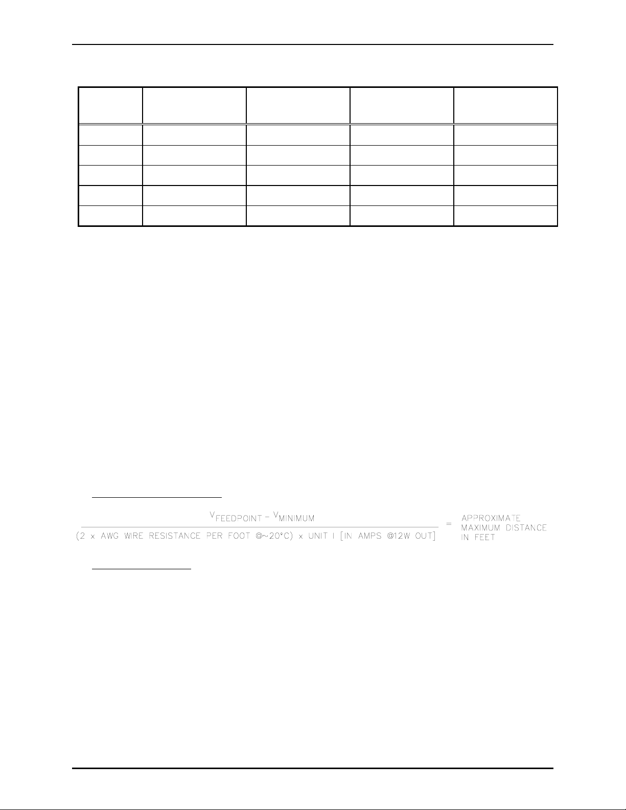
For conditions other than above, the following formula may be helpful in calculating the approximate
maximum distance for a single station.
For continuous tone applications
For speech operation only
with minimum distortion:
, multiply the above result by a factor of 2 to a maximum factor of 4.
Example: What is the approximate maximum distance for a single dc station if the voltage feed is 27.5
V dc and a No. 14 AWG wire is used @ 20º C?
Info:
• No. 14 AWG @ 20º C = ~0.002525 ohms per foot
• Vfeedpoint = 27.5 V dc
Solution:
(27.5 V – 21 V) / ((2 × 0.002525 ohm per foot) × 1.1 amp)
= 6.5 / 0.005555
= 1170 feet (for continuous tone signal) or up to ~4680 feet (× 4) for speech signals
f:\standard ioms - current release\42004 instr. manual s\42004-147g.doc
11/10
Page 4
Pub. 42004-147G
Model 702-002, 732-102, and 733-002 24 V DC Single-Party Amplifier Enclosures Page: 4 of 12
Mounting
The Model 732-102 Weatherproof Metallic Enclosure is supplied with pre-drilled cable openings and
conduit hubs with top and bottom cap plugs in place to prevent contamination. The Model 702-002
Indoor Enclosure and the Model 733-002 Weatherproof Non-metallic Enclosure are not supplied with
conduit or cable openings.
Drill or punch these openings using the template supplied before mounting the enclosure. The
recommended cable entry point is via the bottom of the enclosure near the rear surface to prevent
moisture from dripping onto the terminals or PCBAs. A secondary location for cable entry is in the top
of the enclosure toward the sides. Avoid the top center, as it may interfere with the plug-in amplifier
receptacle. Under no circumstances should cable entries be made in the side of the enclosure as this may
interfere with the installation of the plug-in amplifier.
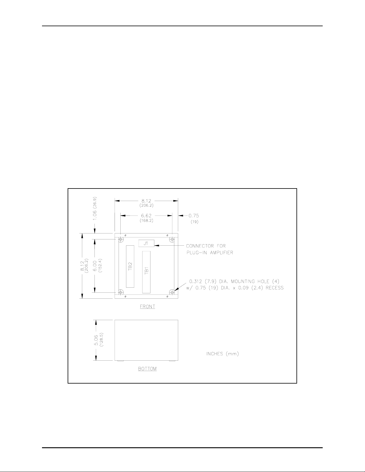
For specific details including mounting hole dimensions, refer to Figure 1 for the Model 702-002 Indoor
Enclosure, Figure 2 for Model 733-002 Weatherproof Non-metallic Enclosure, and Figure 3 for the
Model 732-102 Weatherproof Metallic Enclosure. When mounting the enclosure, use caution to avoid
damaging the terminal blocks inside. The suggested mounting height for all station enclosures is
54 inches (137 cm) up to the centerline of the enclosure.
Figure 1. Model 702-002 Indoor Enclosure Mounting Details
f:\standard ioms - current release\42004 instr. manual s\42004-147g.doc
11/10
Page 5

Pub. 42004-147G
Model 702-002, 732-102, and 733-002 24 V DC Single-Party Amplifier Enclosures Page: 5 of 12
Figure 2. Model 733-002 Outdoor Non-metallic Enclosure Mounting Details
f:\standard ioms - current release\42004 instr. manual s\42004-147g.doc
11/10
Page 6

Pub. 42004-147G
Model 702-002, 732-102, and 733-002 24 V DC Single-Party Amplifier Enclosures Page: 6 of 12
Figure 3. Model 732-102 Outdoor Enclosure Mounting Details
f:\standard ioms - current release\42004 instr. manual s\42004-147g.doc
11/10
Page 7

Pub. 42004-147G
Model 702-002, 732-102, and 733-002 24 V DC Single-Party Amplifier Enclosures Page: 7 of 12
Wiring
Attach conduit to the enclosure. Feed the wiring through the conduit, and bring it into the enclosure. See
Figure 4. Follow the wire colors carefully, because the colors correspond to GAI-Tronics 60038 Series
cable. The wires must be spade-lugged and connected carefully and completely to the terminal block.
An improper termination may diminish station performance.
Local Muting
Figure 7 illustrates local speaker muting when stations are completely assembled and paging operation
occurs. Normally, when the station push-to-page button is pressed, the paging speaker connected to that
station is silenced (muted) to prevent acoustic feedback to the handset microphone. However, while the
handset is in use for party line conversations, the paging speaker is “live” to enable paging calls from
other stations.
To disable the mute feature, follow these instructions:
1. Locate the lugged violet wire attached to terminal point 7 (mute) on the terminal block within the
enclosure.
2. Transfer the lugged violet wire to terminal point 8 (Page L1).
After any muting changes are made, unpack the station amplifier and install.
Mutual Muting
In the event that feedback occurs within an area and repositioning of the system speakers does not help,
mutual muting may be used to correct this problem.
The following steps mutually mutes adjacent amplifiers/handsets within a zone.
1. Ensure that the purple lugged wire is connected to terminal 7 of TB1.
2. Connect terminal TB1-7 of the handset station to TB1-7 of the station within the zone that is causing
feedback. This is done by using the spare system wire (orange conductor) from within the system
cable that runs between the stations.
f:\standard ioms - current release\42004 instr. manual s\42004-147g.doc
11/10
Page 8

Pub. 42004-147G
Model 702-002, 732-102, and 733-002 24 V DC Single-Party Amplifier Enclosures Page: 8 of 12
Figure 4. Wiring Diagram for Model 702-002, 732-102, and 733-002 Enclosures
f:\standard ioms - current release\42004 instr. manual s\42004-147g.doc
11/10
Page 9

Pub. 42004-147G
Model 702-002, 732-102, and 733-002 24 V DC Single-Party Amplifier Enclosures Page: 9 of 12
Maintenance
Regular inspection and a good preventive maintenance program will increase the reliability of your
GAI-Tronics station. The GAI-Tronics Field Service Department can formulate a service contract suited
to your facility’s specific need for preventive maintenance.
®
In addition, the following procedure can be used to keep Page/Party
systems operating effectively.
WARNING
Before performing any of the following preventive maintenance steps,
remove all power from the station.
1. Remove the amplifier from the enclosure.
2. Visually check the interior of the enclosure for signs of contamination such as dust, condensation or
process liquid.
3. Using the No. 10440-002 Maintenance Cable, plug the amplifier into the connector in the enclosure.
Check, and if necessary, adjust the amplifier to maximize performance.
4. Reinstall the amplifier in the enclosure. Ensure that all gaskets and hardware are in place. Failure to
install the gaskets, which also act as spacers, can result in damage to the connectors on the amplifiers
and inside the enclosures and can cause system faults.
It may become necessary to re-terminate some or all of the enclosures in a system. If so, strip the wires
back to clean copper and connect only one wire to each connector to allow for easier future
troubleshooting.
Troubleshooting
The following table lists some hints to aid technicians in troubleshooting.
Problem Solution
Feedback occurs
only during
page.
1. If a speaker is close to the station, try using the muting feature in the amplifier
enclosure at the terminal blocks. Connect the violet wire at TB1-8 to TB1-7.
Refer to Figure 4.
2. Ensure that speakers attached to other stations located nearby are not pointed
in your direction. If changing the orientation of the other speakers has no
effect, mutual muting may be required. Mutual muting silences all the
speakers within proximity to the affected stations during a page from any one
of the mutually muted stations.
Connect the orange wire (spare) to the TB1-7 of all the stations to be mutually
muted. N
OTE: If too many stations are selected, paging coverage can be
adversely affected.
3. Check line terminations at the line balance assembly. Line balance assembly
connections are critical.
Crosstalk
occurs.
One or more system cable pairs may be improperly terminated. Visually inspect
the system cable connections for accidental crossing of the cable pairs or grounds.
f:\standard ioms - current release\42004 instr. manual s\42004-147g.doc
11/10
Page 10

Pub. 42004-147G
Model 702-002, 732-102, and 733-002 24 V DC Single-Party Amplifier Enclosures Page: 10 of 12
Specifications
Model 702-002 Indoor Enclosure
Construction/finish ...................................................... 16-gauge cold-rolled steel/gray polyurethane finish
Mounting............................................................................. Wall or column, four 5/16-inch mounting holes
Connections ................................................................................Internal screw-type barrier terminal blocks
Dimensions ............................................................... 8.1 H × 8.1 W × 5.1 D inches; (206 × 206 × 129 mm)
Shipping weight.................................................................................................................... 5.5 lbs. (2.5 kg)
Approvals
NRTL Listed for USA and Canada.......................................................... Class I, Div. 2, Groups A, B, C, D
CE Mark
Indoor environmental rating................................................ Meets requirements of IP21; Type 2 (Type 20)
Model 732-102 Aluminum
Construction/Finish.................................................................... Sand-cast aluminum alloy, cam-style latch,
hinged door with gasket; gray baked enamel
Mounting......................................................Wall, column, or pole (mounting kit required for pole mount),
four 7/16-inch mounting holes
Connections ................................................................................Internal screw-type barrier terminal blocks
External controls.........................................................................................................Rotary selector switch
Dimensions ............................................................. 14.9 H × 10.8 W × 9.6 D inches (378 × 274 ×244 mm)
Shipping weight.................................................................................................................. 20.4 lbs. (9.3 kg)
Approvals
NRTL Listed for USA and Canada......................................................... Class I, Div. 2, Groups A, B, C, D;
Class II, Div. 2, Groups F and G; Class III, Div. 2
CE Mark
Outdoor environmental rating........................................................................................................... Type 3R
Model 733-002 Non-metallic Weatherproof
Construction/Finish.................................Glass-reinforced polyester, J-hook latch, hinged door with gasket
Mounting......................................................Wall, column, or pole (mounting kit required for pole mount),
four 7/16-inch mounting holes
Connections ................................................................................Internal screw-type barrier terminal blocks
Dimensions .......................................................... 14.6 H × 10.9 W × 10.5 D inches (371 × 276 × 267 mm)
Shipping weight.................................................................................................................... 9.6 lbs. (4.4 kg)
Approvals
NRTL Listed for USA and Canada......................................................... Class I, Div. 2, Groups A, B, C, D;
Class II, Div. 2, Groups F and G; Class III, Div. 2
Outdoor environmental rating............................................................... Type 3R; Type 4X with door closed
f:\standard ioms - current release\42004 instr. manual s\42004-147g.doc
11/10
Page 11

Pub. 42004-147G
Model 702-002, 732-102, and 733-002 24 V DC Single-Party Amplifier Enclosures Page: 11 of 12
REPLACEMENT PARTS
Part No.
Description
10440-002 Maintenance Cable, 16-pin
Model
702-002
Model
732-102
12251-001 Spring Door Kit
12251-002 Spring Door Kit
12505-001 Door
12505-002 Door Handle
12505-003 Door
12504-004 Door Handle
14612-003 Hub, 1.25 inches
25007-004 Closure/Plug (NPT 1.25 inches)
25203-002 Hub Gasket
25405-006 Ground Label
46101-012 Front Panel Screw
61509-016 Harness Assembly
Model
733-002
61509-017 Harness Assembly
f:\standard ioms - current release\42004 instr. manual s\42004-147g.doc
11/10
Page 12

Pub. 42004-147G
Model 702-002, 732-102, and 733-002 24 V DC Single-Party Amplifier Enclosures Page: 12 of 12
f:\standard ioms - current release\42004 instr. manual s\42004-147g.doc
11/10
Page 13

Warranty
Equipment. GAI-Tronics warrants for a period of one (1) year from the date of shipment, that any
GAI-Tronics equipment supplied hereunder shall be free of defects in material and workmanship, shall
comply with the then-current product specifications and product literature, and if applicable, shall be fit
for the purpose specified in the agreed-upon quotation or proposal document. If (a) Seller’s goods prove
to be defective in workmanship and/or material under normal and proper usage, or unfit for the purpose
specified and agreed upon, and (b) Buyer’s claim is made within the warranty period set forth above,
Buyer may return such goods to GAI-Tronics’ nearest depot repair facility, freight prepaid, at which time
they will be repaired or replaced, at Seller’s option, without charge to Buyer. Repair or replacement shall
be Buyer’s sole and exclusive remedy. The warranty period on any repaired or replacement equipment
shall be the greater of the ninety (90) day repair warranty or one (1) year from the date the original
equipment was shipped. In no event shall GAI-Tronics warranty obligations with respect to equipment
exceed 100% of the total cost of the equipment supplied hereunder. Buyer may also be entitled to the
manufacturer’s warranty on any third-party goods supplied by GAI-Tronics hereunder. The applicability
of any such third-party warranty will be determined by GAI-Tronics.
Services. Any services GAI-Tronics provides hereunder, whether directly or through subcontractors,
shall be performed in accordance with the standard of care with which such services are normally
provided in the industry. If the services fail to meet the applicable industry standard, GAI-Tronics will
re-perform such services at no cost to buyer to correct said deficiency to Company's satisfaction provided
any and all issues are identified prior to the demobilization of the Contractor’s personnel from the work
site. Re-performance of services shall be Buyer’s sole and exclusive remedy, and in no event shall GAITronics warranty obligations with respect to services exceed 100% of the total cost of the services
provided hereunder.
Warranty Periods. Every claim by Buyer alleging a defect in the goods and/or services provided
hereunder shall be deemed waived unless such claim is made in writing within the applicable warranty
periods as set forth above. Provided, however, that if the defect complained of is latent and not
discoverable within the above warranty periods, every claim arising on account of such latent defect shall
be deemed waived unless it is made in writing within a reasonable time after such latent defect is or
should have been discovered by Buyer.
Limitations / Exclusions. The warranties herein shall not apply to, and GAI-Tronics shall not be
responsible for, any damage to the goods or failure of the services supplied hereunder, to the extent
caused by Buyer’s neglect, failure to follow operational and maintenance procedures provided with the
equipment, or the use of technicians not specifically authorized by GAI-Tronics to maintain or service the
equipment. THE WARRANTIES AND REMEDIES CONTAINED HEREIN ARE IN LIEU OF AND
EXCLUDE ALL OTHER WARRANTIES AND REMEDIES, WHETHER EXPRESS OR IMPLIED BY
OPERATION OF LAW OR OTHERWISE, INCLUDING ANY WARRANTIES OF
MERCHANTABILITY OR FITNESS FOR A PARTICULAR PURPOSE.
Return Policy
If the equipment requires service, contact your Regional Service Center for a return authorization number
(RA#). Equipment should be shipped prepaid to GAI-Tronics with a return authorization number and a
purchase order number. If the equipment is under warranty, repairs or a replacement will be made in
accordance with the warranty policy set forth above. Please include a written explanation of all defects to
assist our technicians in their troubleshooting efforts.
Call 800-492-1212 (inside the USA) or 610-777-1374 (outside the USA) for help identifying the
Regional Service Center closest to you.
(Rev. 10/06)
 Loading...