

Page 1

Pub. 42004-425A
GAI-TRONICS® CORPORATION
A HUBBELL COMPANY
732-101 Singl e-Party Weatherproof
Aluminum 115 V AC Amplifi er Enclosure
Confidentiality Notice
This manual is provided s olely as an operational, installation, and maint enance guide and contains sensitive
bus ines s and technic al information that is c onf ident ial and p roprietary to GAI- Tronic s. GAI- Tronic s retains
all intellectual property and other r ights in or to the information contained herein, and suc h inf ormation ma y
only be used in connection with the op erat ion of your GAI - Tronic s pr odu ct or system. This manual may not
be disclos ed in any form, in whole or in part, directly or indirect ly, to a ny third part y.
General Information
This manual applies to the GAI-Tronics 732-101 Single-Party Weatherproof Aluminum 115 V AC
Amplifier Enclosure, which is an important component of the 700 series Page/Party
enclosure is configu red for s ingle- par ty syst ems.
®
system. This
The 732-101 Enclosure is made of cast aluminum alloy, which is extremely weatherproof and corrosionresistant. It is equipped with terminal strips f or connecting system ca ble. The 701 and 751 series
Amplifiers mate directly with this enclosure.
Installation
CAUTION
the approval list ing in the S pe c ification section of this manual. Such installation may cause a safety
hazard and consequent injury or property damage.
When installing an a dd- on sta tion, cons ult the s ys tem layout diagram at t he end of this manual. This
figure, when used in conju nc tion with the s tat ion installation information and cable layout guide, shou ld
provide all the informa tion necessa ry to install additional Page/Party< stations .
Enclos ure Placement
All GAI-Tronics Page/Party® units are wir ed in p arallel. Good system layout design minimizes the cable
required for eac h installation. GAI-Tronics mult i- c onductor cabl e, des i gned esp eci ally for this ap plicat ion,
is recommended. The number, size, and color-c oding of c onductors are listed in t he accompa nying system
connection diagra m.
System layout and power c able length are very importa nt when installing Pa ge/ Party< equipment.
Although it varies f or differ ent syst ems, the genera l guideline is that the tot al power cable length should not
exceed one mile (5280 feet) for 115 V ac systems. The total cable length is the most important
consideration while cable length bet ween the stat ions is genera lly not a factor.
Do not install this equipment in hazardous areas other than those indicated on
GAI-T r onics Corporation 400 E. Wyomissing Ave. Mohnton, P A 19540 US A
610-777-1374 800-492-1212 Fax : 610-796-5954
ISIT WWW.GAI-TRONICS.COM FOR PRODUCT LITERATURE AND MANUALS
V
Page 2
Pub. 42004-425A
732-101 Single-Party Weatherproof Alum inum 115 V AC Amplifier Enclosure Page:
2 of 7
Mounting
The 732-101 Single-Party Weatherproof Aluminum Enclosure is supplied with pre-drilled cable openings
and condu it hubs with top and bottom cap p l ugs in place to prevent contamination.
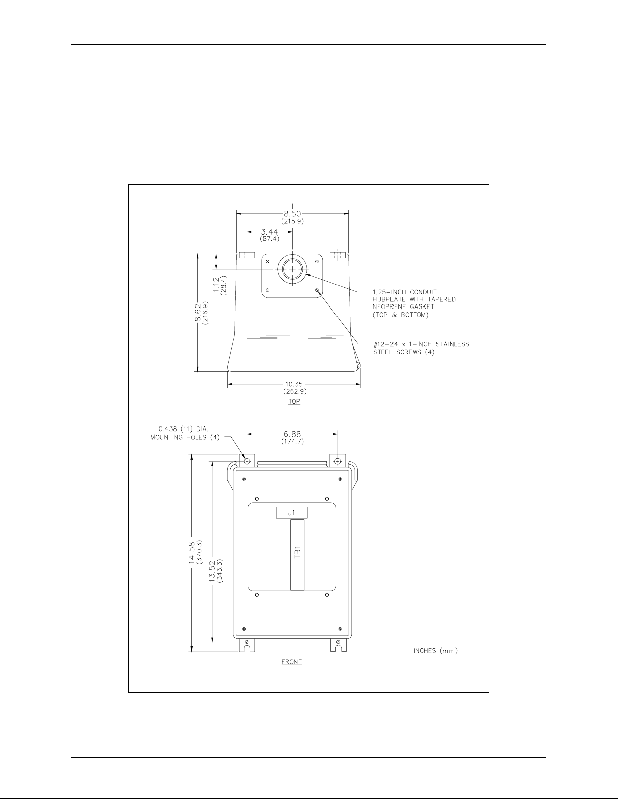
For specific details inclu ding mounting hole dimensions, refer to Figure 1 . When mounting t he enclos ure,
use caution to avoid da ma ging the termina l blocks insi de. The su gges ted mounting height for all s tat ion
enclosures is 54 inches (137 cm) up to the centerline of the enclosure.
Figure 1. 732-101 Single-Party Weatherproof Aluminum Enclosure Mounting
f:\standard ioms - current release\ 42004 ins t r. m anuals \ 42004-425a.doc
04/09
Page 3

Pub. 42004-425A
732-101 Single-Party Weatherproof Alum inum 115 V AC Amplifier Enclosure Page:
3 of 7
Wiring
Attach the condu it to the enclos ure. Feed the wiring t hrough the conduit and bring it into the enclosu re.
See Figu re 2. Follow the wire colors carefu lly because the colors correspond t o G AI - Tronic s 60038 Series
cab le. The wir es mu st be spade-lugged and connected carefully and completely to the termina l block. An
improper termina tion may res ult in diminished station p erformanc e.
Local Muting
Figure 2 illus tra tes local speaker muting when sta tions a re completely as sembled and pa ging operation
occurs. Normally, when the station button is pressed, the paging speaker connect ed t o that station is
silenced (muted) to pr event acous tic feedba c k to the hands et microphone. However, while the handset is in
use for party line conver sations, the p aging speaker is “live” to enab le p aging calls from other stations.
To d i sable th e mute feature, fol l o w these i n struc tions:
1. Locate the lugged violet wire attached to terminal point 7 (mute) on the terminal block within the
enclosure.
2. Transf er the lugged violet wir e to terminal p oint 8 (P age L1).
After any muting changes are made, unpack t he s tat ion amplifier and install.
Mutual Muting
In the event that feedback occu rs wit hin an area a nd repositioning of the system spea kers does not help ,
mutual muting may be used to correct this problem.
The following steps mutually mutes adjacent amplifiers /handset s within a z one.
1. Ensure tha t the purple lugged wire is connected t o terminal 7 of TB1.
2. Connect terminal TB1-7 of the handset st ation t o TB1-7 of the stat ion within the zone that is causing
feedback. This is done by using the spare system wire (orange conduc tor) f rom within the system
ca ble th at run s between th e statio n s.
f:\standard ioms - current release\ 42004 ins t r. m anuals \ 42004-425a.doc
04/09
Page 4

Pub. 42004-425A
732-101 Single-Party Weatherproof Alum inum 115 V AC Amplifier Enclosure Page:
4 of 7
Figure 2. Wiring Diagram
f:\standard ioms - current release\ 42004 ins t r. m anuals \ 42004-425a.doc
04/09
Page 5

Pub. 42004-425A
732-101 Single-Party Weatherproof Alum inum 115 V AC Amplifier Enclosure Page:
5 of 7
Maintenance
Regula r inspection and a good preventive ma intenance progra m will increase the reliability of your
GAI-Tronics station. The GAI-T ronics F i eld Service Department c an formul ate a service contract suited
to your facility’s s p ecific need for preventive maintenanc e.
®
In addition, the f ollowing p rocedure can be u sed to keep Page/Party
systems o perating eff ectivel y .
WARNING
Before performing any of the following preventive maintenance steps, remove
all power from the station.
1. Remove the amplifi er from th e en closure.
2. Visually check the interior of the enclosure for s i gns of contamination s uch as dust , condensa tion or
process liquid.
3. Using the No. 10440-002 Maintenance Cable, plug the amplifier into the connector in the enclosure.
Check, and if necessary, adjus t the amplif ier to maximize performa nc e.
4. Reinstall the amplif ier in the enclosure. Ensure that all gaskets and hardware are in place. Failure t o
install the gas kets, which also act a s spacers, can result in damage to t he connectors on the amplifier s
and insi de t he enclosures and can cau se syst em faults.
It may become necessary to re-terminate some or all of the enclosures in a system. If so, strip the wires
bac k to clean c opper and connect only one wire to each c onnector t o allow for easier futu re
troubleshooting.
Troubleshooti ng
The following t able list s some hints t o aid technicians in t roubles hooting.
Problem Solution
Feedback occurs
only duri ng
page.
1. If a speaker is close to the sta tion, try using the muting featur e in t he amplifier
enclosure at the termina l blocks. Connect t he violet wire at TB1- 8 to TB1-7.
Refer to the wiring diagram.
2. Ensu re that speakers attached to ot her stations loc ated nearby a re not pointed in
your direction. If changing the orient ation of the other s peakers has no effect,
mutual muting may b e required. Mutu al muting s ilences all the sp eakers within
proximity to the affected s tat ions duri ng a pa ge from any one of the mutually
muted st ations .
Connect the orange wire (spare) to the TB1-7 of all the st ations to be mutu ally
muted. N
OTE: If too many stations are selected, paging cover age can b e
adver sely affec ted.
3. Check line ter mina tions at the line balance as sembly. Line balance a ssembly
connections are critical.
Crosstalk
occurs.
One or more system ca ble pairs ma y be improperly terminated . Vis ual l y i n spec t the
system cable connect ions for accidental cr ossing of the cable p airs or gr ounds.
f:\standard ioms - current release\ 42004 ins t r. m anuals \ 42004-425a.doc
04/09
Page 6

Pub. 42004-425A
732-101 Single-Party Weatherproof Alum inum 115 V AC Amplifier Enclosure Page:
6 of 7
Specifications
Construction/Finish...................................................................Sand-cast aluminum alloy, cam-style latch,
hinged door with gasket; gray baked ena mel
N
Mounting......................................................Wall, column, or pole (mounting kit required for pole mount),
four 7/16-inch mounting holes
Connections ...............................................................................Internal screw-type barrier terminal blocks
Dimensions ........................................................... 14.9 H × 10.8 W × 9.6 D inches (378 × 274 ×244 mm)
Shipping weight.............................................................................................................. 19.7 lbs. (8.9 kg)
Net weight...................................................................................................................... 17.7 lbs. (8.0 kg)
Approvals.....................NRTL Listed for USA and Canada.................Class I, Div. 2, Groups A, B, C, D;
Class II, Div. 2, Groups F and G; Class III, Div. 2
Out door environmenta l rating ........................................................................................................Type 3R
Replacement Parts
OTE: Earlier models could vary in color
Part No. Description
10440-002 Maintenance Cable, 16-pin
12505-001 Door
12505-002 Door Handle
12566-001 Hub, 1.25 inches
25007-004 Closure/Plug (NPT 1.25 inches)
25203-002 Hub Gasket
25405-006 Ground Label
61509-004 Harness Assembly
f:\standard ioms - current release\ 42004 ins t r. m anuals \ 42004-425a.doc
04/09
Page 7

Pub. 42004-425A
732-101 Single-Party Weatherproof Alum inum 115 V AC Amplifier Enclosure Page:
7 of 7
f:\standard ioms - current release\ 42004 ins t r. m anuals \ 42004-425a.doc
04/09
Page 8

Warranty
Equipment. GAI-Tronics warrants for a period of one (1) year from the date of shipment, that any
GAI-Tronics equipment supplied hereunder shall be free of defects in material and workmanship, shall
comply with the then-current product specifications and product literature, and if applicable, shall be fit
for the purpose specified in the agreed-upon quotation or proposal document. If (a) Seller’s goods prove
to be defective in workmanship and/or material under normal and proper usage, or unfit for the purpose
specified and agreed upon, and (b) Buyer’s claim is made within the warranty period set forth above,
Buyer may return such goods to GAI-Tronics’ nearest depot repair facility, freight prepaid, at which time
they will be repaired or replaced, at Seller’s option, without charge to Buyer. Repair or replacement shall
be Buyer’s sole and exclusive remedy. The warranty period on any repaired or replacement equipment
shall be the greater of the ninety (90) day repair warranty or one (1) year from the date the original
equipment was shipped. In no event shall GAI-Tronics warranty obligations with respect to equipment
exceed 100% of the total cost of the equipment supplied hereunder. Buyer may also be entitled to the
manufacturer’s warranty on any third-party goods supplied by GAI-Tronics hereunder. The applicability
of any such third-party warranty will be determined by GAI-Tronics.
Services. Any services GAI-Tronics provides hereunder, whether directly or through subcontractors,
shall be performed in accordance with the standard of care with which such services are normally
provided in the industry. If the services fail to meet the applicable industry standard, GAI-Tronics will
re-perform such services at no cost to buyer to correct said deficiency to Company's satisfaction provided
any and all issues are identified prior to the demobilization of the Contractor’s personnel from the work
site. Re-performance of services shall be Buyer’s sole and exclusive remedy, and in no event shall GAITronics warranty obligations with respect to services exceed 100% of the total cost of the services
provided hereunder.
Warranty Periods. Every claim by Buyer alleging a defect in the goods and/or services provided
hereunder shall be deemed waived unless such claim is made in writing within the applicable warranty
periods as set forth above. Provided, however, that if the defect complained of is latent and not
discoverable within the above warranty periods, every claim arising on account of such latent defect shall
be deemed waived unless it is made in writing within a reasonable time after such latent defect is or
should have been discovered by Buyer.
Limitations / Exclusions. The warranties herein shall not apply to, and GAI-Tronics shall not be
responsible for, any damage to the goods or failure of the services supplied hereunder, to the extent
caused by Buyer’s neglect, failure to follow operational and maintenance procedures provided with the
equipment, or the use of technicians not specifically authorized by GAI-Tronics to maintain or service the
equipment. THE WARRANTIES AND REMEDIES CONTAINED HEREIN ARE IN LIEU OF AND
EXCLUDE ALL OTHER WARRANTIES AND REMEDIES, WHETHER EXPRESS OR IMPLIED BY
OPERATION OF LAW OR OTHERWISE, INCLUDING ANY WARRANTIES OF
MERCHANTABILITY OR FITNESS FOR A PARTICULAR PURPOSE.
Return Policy
If the equipment requires service, contact your Regional Service Center for a return authorization number
(RA#). Equipment should be shipped prepaid to GAI-Tronics with a return authorization number and a
purchase order number. If the equipment is under warranty, repairs or a replacement will be made in
accordance with the warranty policy set forth above. Please include a written explanation of all defects to
assist our technicians in their troubleshooting efforts.
Call 800-492-1212 (inside the USA) or 610-777-1374 (outside the USA) for help identifying the
Regional Service Center closest to you.
(Rev. 10/06)
 Loading...