

Page 1

Pub. 42004-690L2C
GAI-TRONICS® CORPORATION
A HUBBELL COMPANY
Model 727-001
Desk Set Access Panel
Confidential ity Notice
This manual is provided solely as an operational, installation, and maintenance guide and contains sensitive
business and technical information that is confidential and proprietary to GAI-Tronics. GAI-Tronics
retains all intellectual property and other rights in or to the information contained herein, and such
information may only be used in connection with the operation of your GAI-Tronics product or system.
This manual may not be disclosed in any form, in whole or in part, directly or indirectly, to any third party.
Introduction
The Model 727-001 Access Panel is a component of the SmartSeries ADVANCE system that can be used
for public address, intercommunication, and emergency notification.
How to Use the Assembly
Application
The Model 727-001 Desk Set Access Panel is used to communicate, initiate alarms and to control alarm
and paging destinations. It is equipped with a 120 V ac/240 V ac desktop power supply that allows the
access panel to be used in almost all installations without requiring additional line transformers.
The Model 727-001 Access Panel consists of the following main components:
27 configurable push buttons
A LAMP TEST push button
A total of 24 configurable LEDs available
Handset with pressbar
Speaker with volume control
Twenty-four of the 27 push buttons contain bi-color LED lamps that can be configured to provide system
status information.
The panel provides a handset equipped with an integral pressbar. The handset is used to make page
announcements and to hold two-way party line conversations. In addition, an internal speaker is provided
to allow page audio monitoring. The access panel also includes a volume control for the internal speaker.
OTE: The speaker is disabled when the handset is in use.
N
GAI-Tronics Corporation 400 E. Wyomissing Ave. Mohnton, PA 19540 USA
610-777-1374 800-492-1212 Fax: 610-796-5954
V
ISIT WWW.GAI-TRONICS.COM FOR PRODUCT LITERATURE AND MANUALS
Page 2
Pub. 42004-690L2C
Model 727-001 Desk Set Access Panel Page 2 of 10
The function of each of the 27 push buttons and 24 available LEDs is configurable using the GAI-Tronics
ADVANCE system software.
Hardware Configuration
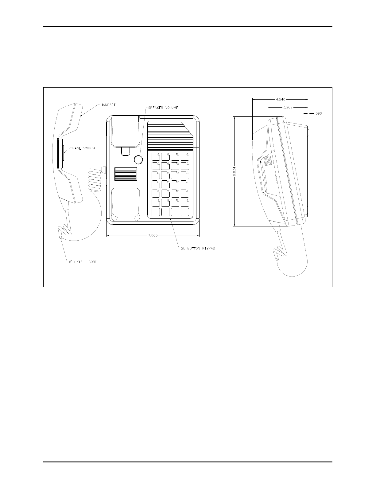
Figure 1. Model 727-001 Desk Set Access Panel
Interfaces
A 3-conductor ac power cord is included with the access panel. One end of the power cord is connected
to the 3-prong connector located on the back of the power supply, while the other end is plugged into a
grounded ac electrical outlet.
The compatible ac input voltages are 120 V ac/240 V ac (auto-ranging), 50/60 Hz. The 5-pin DIN plug
from the power supply is connected to the 5-pin DIN jack on the rear of the access panel as shown in
Figure 3.
f:\standard ioms - current release\42004 instr. man uals\42004-690l2c.doc
03/13
Page 3
Pub. 42004-690L2C
Model 727-001 Desk Set Access Panel Page 3 of 10
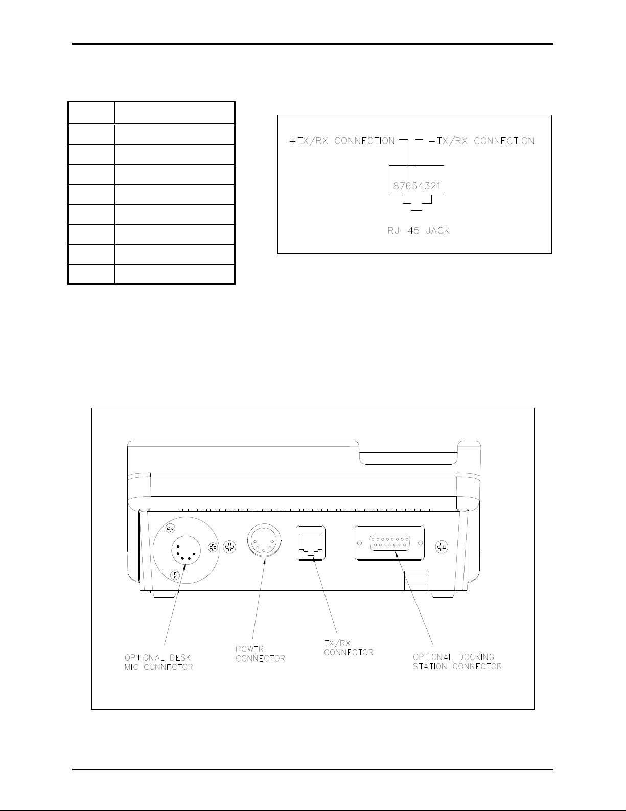
The data and audio connection to the system control unit is provided by an RJ-45 jack on the rear of the
access panel as shown in Figure 2. The following are the physical connections of the RJ-45 jack:
Pin Connection
1 No connection
2 No connection
3 No connection
4 No connection
5 − TX/RX connection
6 + TX/RX connection
7 No connection
8 No connection
Figure 2.
The 5-pin XLR jack is used for connection of an optional desk mic as shown in Figure 3.
The DB-15 connector on the rear of the access panel is used for connecting the desk set to the optional
docking station. This connection allows the user to connect the power and the data/audio connection to
the rear of the docking station to ease overall installation of the docking station.
Figure 3. Model 727-001 Access Panel Typical Connections (Rear View)
f:\standard ioms - current release\42004 instr. man uals\42004-690l2c.doc
03/13
Page 4

Pub. 42004-690L2C
Model 727-001 Desk Set Access Panel Page 4 of 10
Installation
WARNING
and in the installation manual.
1. Disconnect power before servicing.
2. Avoid servicing the unit during electrical storms.
3. Do not touch uninsulated wires.
Please adhere to all warnings, safety, and operating instructions on the unit
Mounting
Remove the access panel from its protective packing. Simply position the access panel on a sturdy
horizontal surface in a convenient location where the handset and push buttons are readily accessible.
Data Connection
Connect the RJ-11 data cable from the RJ-45 jack on the rear of the unit to the API connecting block
located in the ADVANCE control cabinet. If the 7-foot cable is not long enough, use a twisted-pair cable
terminated on one end with either an RJ-11 or RJ-45 plug. This connection is not polarity-sensitive and
may be wired in either orientation.
OTE: This assembly includes a 7-foot RJ-11 data cable.
N
Power
Connect the 3-conductor ac power cord provided with the access panel as follows:
1. Plug one end of the power cord into the 3-prong power connector at the rear of the power supply.
2. Plug the 5-pin DIN connector of the power supply into the 5-pin DIN jack on the rear of the access
panel.
3. Plug the power supply cord into a grounded ac electrical outlet.
4. The access panel does not contain an integral power switch. The access panel will power up
immediately.
f:\standard ioms - current release\42004 instr. man uals\42004-690l2c.doc
03/13
Page 5

Pub. 42004-690L2C
Model 727-001 Desk Set Access Panel Page 5 of 10
Label Creation
A Word 97 document is available to create custom slide-in labels for the desk set. It is available for
download at www.gai.tronics.com
When you click on the document, you will be asked if you want to download the file; or if MS Word is
installed on your computer, it will open automatically. You may want to save the file on your computer
for future use.
Before printing on the included slide-in labels, print a test page on plain paper to verify that the
positioning, the orientation, and the information are correct. To check the printed paper, lay it behind the
included slide-in label sheet and verify that the print is in the proper location. Because printers vary, you
may need to adjust the margins in the page setup to center the printed text within the perforated strips.
To modify the text size and color of the text in the blocks, you will need to “unprotect” the document as
outlined below.
If you need to modify the margins you will need to perform the following steps:
1. Unprotect the document by selecting the Tools Menu, then clicking on Unprotect Document.
. Follow the SmartSeries link, and select Access Panels.
2. Next select File, then Page Setup.
3. Adjust the Top Margin and Left Margin value to move the printed text around on the sheet.
OTE: Do not re-protect the document, otherwise all the information that was typed in will be lost.
N
After making any change to the slide-in label document, print a test copy on plain paper before using the
included slide-in label sheet.
To change the color of a cell or square:
1. Right click at the left edge of a cell to select the entire cell. The cell will reverse color.
2. Select Format, Borders and Shading, and then select the Shading tab.
3. Select a color from the chart by clicking on it; and be sure the “Applies to box” reads “cell” and then
click OK to apply.
The color will appear correctly when the cursor is moved to another location in the document.
f:\standard ioms - current release\42004 instr. man uals\42004-690l2c.doc
03/13
Page 6

Pub. 42004-690L2C
Model 727-001 Desk Set Access Panel Page 6 of 10
Keypad Slide-In Labels
To install the keypad slide-in labels, proceed as
follows:
1. Separate the slide-in labels along the perforated
lines on the sheet.
2. Fold the tab at the end of the slide-in label so
that it is perpendicular to the reset of the label.
3. Slide the label into the appropriate slot opening
located at the top of each of the button columns.
4. Repeat the above steps for the remaining labels.
To replace the keypad slide-in labels, proceed as
follows:
1. Locate the tab at the top of the label and pull it
out from behind.
2. Slide label out using the tab that has been
exposed.
Figure 4. Button Layout
Button Layout and Default Configurations
For units to be used without a docking station, all buttons and 24 LEDs are available for use.
For units being used with a docking station:
ACK/NEXT button should be configured as button #26 and LED #20.
PREV button should be configured as button #27.
OTE: LED #20 on the desk-set keypad will flash when the ACK/NEXT button on the docking station is
N
flashing, unless it is disabled.
Configurable Push Buttons
The 27 configurable push buttons can be configured for the following functions:
Initiating voice pages and alarms
Selecting zones
Routing voice pages and alarms
Selecting and resetting alarm and fault condition messages
Acknowledging system status
Selecting party lines
Activating relay groups
f:\standard ioms - current release\42004 instr. man uals\42004-690l2c.doc
03/13
Page 7

Pub. 42004-690L2C
Model 727-001 Desk Set Access Panel Page 7 of 10
Operation
Operation of this assembly is highly dependent on the attached system’s software configuration. The
software is factory-created and subsequently downloaded to the system control unit via an external PC at
system start-up.
This access panel offers the standard features described below in addition to other configurable features.
The standard features include a handset used for page and party functions, and an integral speaker to
monitor page audio.
Handset Communications
The handset is used for both page and party communications. Lifting the handset from the cradle creates
an off-hook condition. In a normal configuration, lifting the handset causes it to be connected to a party
line.
Speaker and Speaker Muting
The access panel’s integral speaker provides the capability of monitoring system page activity. The
speaker’s volume can be adjusted using the volume adjustment knob.
N
OTE: The speaker is disabled when the handset is in use.
f:\standard ioms - current release\42004 instr. man uals\42004-690l2c.doc
03/13
Page 8

Pub. 42004-690L2C
Model 727-001 Desk Set Access Panel Page 8 of 10
How to Diagnose Assembly Faults
Servicing Guideli nes
1. Notify plant personnel of a system shutdown prior to servicing the unit.
2. Disconnect power before connecting external wiring or installing or removing the access panel.
Symptom Action
Access panel does not function.
(No push buttons detected, no
LED lamps active, and handset is
not functioning.)
LEDs are blinking and the
sounder is beeping
No configurable push buttons are
detected.
Some configurable push buttons
are not detected.
No LED lamps of any
configurable push buttons
activate.
Some LED lamps of configurable
push buttons do not activate.
Speaker does not function.
Verify ac power is applied to power supply. Verify that ac
power cord is plugged in. Also verify that ac outlet is active.
Verify that the LED is lit on top of the desktop power supply.
Call for service of the access panel.
Verify that the data cable is properly connected between the access
panel and the control unit.
Verify that the data cable is properly connected between the
access panel and the control unit.
Call for service of the access panel.
Call for service of the access panel.
Call for service of the access panel.
Call for service of the access panel.
Ensure that the speaker volume control is not turned down.
Call for service of the access panel.
Handset does not function
properly.
f:\standard ioms - current release\42004 instr. man uals\42004-690l2c.doc
03/13
Call for service of the access panel.
Page 9

Pub. 42004-690L2C
Model 727-001 Desk Set Access Panel Page 9 of 10
Specification s
Electrical
Input voltage .................................................................................................................... 120 V ac/240 V ac
Auto-ranging
Input frequency ............................................................................................................................... 50/60 Hz
Input current draw (with lamp test depressed) ................................................. 60 mA @ 120 V ac, nominal
200 mA @ 120 V ac, maximum
Environmental
Operating temperature range .................................................................. +32 F to +120 F (0 C to +49 C)
Relative humidity ................................................................................................ Non-condensing 85% max.
Mechanical
Unit dimensions ........................................... 7.60 W 8.93 L 4.63 D inches (193.0 226.9 117.6 mm)
Unit weight.......................................................................................................................................... 4.6 lbs.
Handset material .......................................................................................................................... Black ABS
Handset microphone ........................................................................................................................ Dynamic
Handset receiver ............................................................................................................................... Dynamic
Handset cord ....................................................................................... Hytrel, 6-foot (1.8 m) when extended
Handset cradle ............................................................................................. Fixed, built-in off-hook detector
External controls ........................................................................................................... Press-to-page switch
27 configurable push buttons
Lamp test button
24 Bi-color LEDs
Speaker volume control
f:\standard ioms - current release\42004 instr. man uals\42004-690l2c.doc
03/13
Page 10

Pub. 42004-690L2C
Model 727-001 Desk Set Access Panel Page 10 of 10
Optional Accessories
Model Number Description
12576-500 Desk Set Access Panel Docking Station with VFD
13610-002 Desk-top Access Panel Desk Mic
Replacement Parts
Model Number Description
14919-113 Keypad Replacement Slide-In Labels (set of 4)
51035-013 Replacement 28-Button Keypad
10119-001 Replacement Handset
61002-007 Replacement Line Cord
Ref erence Material
Reference to Assembly/Model Drawings
Published by Title GAI-Tronics Ref. No.
GAI-Tronics Model 727-001 Desk Set Access Panel Outline 73058
f:\standard ioms - current release\42004 instr. man uals\42004-690l2c.doc
03/13
Page 11

Warranty
Equipment. GAI-Tronics warrants for a period of one (1) year from the date of shipment, that any
GAI-Tronics equipment supplied hereunder shall be free of defects in material and workmanship, shall
comply with the then-current product specifications and product literature, and if applicable, shall be fit
for the purpose specified in the agreed upon quotation or proposal document. If (a) Seller’s goods prove
to be defective in workmanship and/or material under normal and proper usage, or unfit for the purpose
specified and agreed upon, and (b) Buyer’s claim is made within the warranty period set forth above,
Buyer may return such goods to GAI-Tronics nearest depot repair facility, freight prepaid, at which time
they will be repaired or replaced, at Seller’s option, without charge to Buyer. Repair or replacement shall
be Buyer’s sole and exclusive remedy. The warranty period on any repaired or replacement equipment
shall be the greater of the ninety (90) day repair warranty or one (1) year from the date the original
equipment was shipped. In no event shall GAI-Tronics warranty obligations with respect to equipment
exceed 100% of the total cost of the equipment supplied hereunder. Buyer may also be entitled to the
manufacturer’s warranty on any third-party goods supplied by GAI-Tronics hereunder. The applicability
of any such third-party warranty will be determined by GAI-Tronics.
Services. Any services GAI-Tronics provides hereunder, whether directly or through subcontractors,
shall be performed in accordance with the standard of care with which such services are normally
provided in the industry. If the services fail to meet the applicable industry standard, GAI-Tronics will reperform such services at no cost to buyer to correct said deficiency to Company's satisfaction provided
any and all issues are identified prior to the demobilization of the Contractor's personnel from the work
site. Re-performance of services shall be Buyer's sole and exclusive remedy, and in no event shall GAITronics warranty obligations with respect to services exceed 100% of the total cost of the services
provided hereunder.
Warranty Periods. Every claim by Buyer alleging a defect in the goods and/or services provided
hereunder shall be deemed waived unless such claim is made in writing within the applicable warranty
periods as set forth above. Provided, however, that if the defect complained of is latent and not
discoverable within the above warranty periods, every claim arising on account of such latent defect shall
be deemed waived unless it is made in writing within a reasonable time after such latent defect is or
should have been discovered by Buyer.
Limitations / Exclusions. The warranties herein shall not apply to, and GAI-Tronics shall not be
responsible for, any damage to the goods or failure of the services supplied hereunder, to the extent
caused by Buyer’s neglect, failure to follow operational and maintenance procedures provided with the
equipment, or the use of technicians not specifically authorized by GAI-Tronics to maintain or service the
equipment. THE WARRANTIES AND REMEDIES CONTAINED HEREIN ARE IN LIEU OF AND
EXCLUDE ALL OTHER WARRANTIES AND REMEDIES, WHETHER EXPRESS OR IMPLIED BY
OPERATION OF LAW OR OTHERWISE, INCLUDING ANY WARRANTIES OF
MERCHANTABILITY OR FITNESS FOR A PARTICULAR PURPOSE.
Return Policy
If the equipment requires service, contact your Regional Service Center for a return authorization number
(RA#). Equipment should be shipped prepaid to GAI-Tronics with a return authorization number and a
purchase order number. If the equipment is under warranty, repairs or a replacement will be made in
accordance with the warranty policy set forth above. Please include a written explanation of all defects to
assist our technicians in their troubleshooting efforts.
Call 800-492-1212 (inside the USA) or 610-777-1374 (outside the USA) for help identifying the
Regional Service Center closest to you.
(Rev. 10/06)
 Loading...