

Page 1
Pub. 42004-684L2B
GAI-TRONICS® CORPORATION
A HUBBELL COMPANY
Model 7245-005 Indoor
Remote Subset Amplifier Enclosure
Confidential ity Notice
This manual is provided solely as an operational, installation, and maintenance guide and contains
sensitive business and technical information that is confidential and proprietary to GAI-Tronics. GAITronics retains all intellectual property and other rights in or to the information contained herein, and
such information may only be used in connection with the operation of your GAI-Tronics product or
system. This manual may not be disclosed in any form, in whole or in part, directly or indirectly, to any
third party.
General Information
Product Overview
The Model 7245-005 Indoor Remote Subset Amplifier Enclosure is intended for use in GAI-Tronics
Page/Party
field cabling of subset stations to be remotely mounted. This indoor amplifier enclosure is constructed of
fabricated steel and is equipped with a 24-position remote subset connector.
®
and SmartSeries ADVANCE systems. The enclosure enables the amplifier, speaker, and
System Requi rements and Limitations
For proper operation, the Model 7245-005 Amplifier Enclosure must be installed with a Model 723-005
or 723-905 Remote Amplifier and with a subset from the following list:
Single Party Subsets: Multi-Party Subsets:
Model 726-101 Desktop Subset Model 7265-101 Desktop Subset (5-party)
Model 711-102 Desk-Edge Subset Model 7115-102 Desk-Edge Subset (5-party)
Model 716-102 Flush-Mount Subset Model 7165-102 Flush-Mount Subset (5-party)
The amplifier enclosure must be mounted within 8 feet of the subset due to the subset cable limitations.
In addition, the amplifier enclosure must be mounted at an indoor location - the amplifier enclosure is not
designed for outdoor use.
In order to provide SmartSeries features, the amplifier enclosure must be connected to a Model 723-905
Remote SmartSeries Subset Amplifier. The SmartVolume™ feature is not supported for the
Model 7265-101 Subset. Also, the SmartVolume™ feature is not supported for speakers equipped with
L-pads or for multiple speaker applications.
GAI-Tronics Corporation 400 E. Wyomissing Ave. Mohnton, PA 19540 USA
610-777-1374 800-492-1212 Fax: 610-796-5954
V
ISIT WWW.GAI-TRONICS.COM FOR PRODUCT LITERATURE AND MANUALS
Page 2
Pub. 42004-684L2B
Model 7245-005 Indoor Remote Subset Amplifier Enclosure Page: 2 of 9
The Model 723-005 or -905 Remote Amplifier is designed only for use with the magnetic hookswitch
subsets listed in the System Requirements section of this manual. Subsets containing an RF hookswitch
are not supported.
In order to provide Page/Party
Remote Subset Amplifier.
®
features, the amplifier enclosure must be connected to a Model 723-005
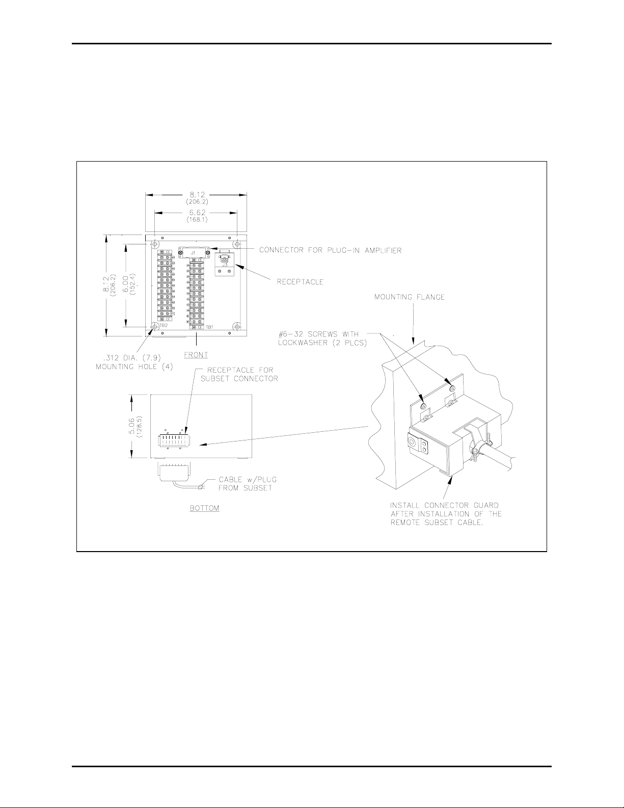
Figure 1. Model 7245-005 Outline Detail
f:\standard ioms - current release\42004 instr. manuals\42004-684l2b.doc
11/10
Page 3

Pub. 42004-684L2B
Model 7245-005 Indoor Remote Subset Amplifier Enclosure Page: 3 of 9
Fea tures and Functions
The Model 7245-005 Indoor Remote Subset Amplifier Enclosure provides terminations for the following:
• Connectorized subset cabling • System cabling
• Plug-in remote amplifier • Auxiliary input signals (SmartSeries stations only)
• External speaker(s)
Description of Major Components
For the following discussion, refer to Figure 2, which provides a block diagram of the enclosure. The
Model 7245-005 Amplifier Enclosure can be divided into 3 primary sections. Each of these sections is
described in greater detail below.
Subset Connector
The 24-position subset connector J2 links the remote subset with the amplifier and enclosure. This
interface enables the microphone, receiver, hookswitch, page switch, party line, speaker, and auxiliary
input signals of the subset to be connected to the amplifier and system cabling.
Amplifier Connector
The 16-position amplifier connector J1 and 6-position amplifier connector J3 links the amplifier with the
subset and system cabling. This interface enables the ac power, microphone, receiver, hookswitch, page
switch, party line, page line, speaker, mute, and auxiliary input signals of the amplifier to be connected to
the subset and system cabling.
Terminal Blocks
Terminal blocks TB1 and TB2 provide connection points for the system cable, an 8-ohm or 16-ohm
speaker, and the auxiliary inputs signals. In addition, the terminal blocks provide connectivity to the
subset receptacle and remote subset amplifier connector.
f:\standard ioms - current release\42004 instr. manuals\42004-684l2b.doc
11/10
Page 4

Pub. 42004-684L2B
Model 7245-005 Indoor Remote Subset Amplifier Enclosure Page: 4 of 9
Block Diagram
Figure 2. Block Diagram
Installation
General Information
For additional system installation, operation, and maintenance information consult the Installation of
GTC 700 Series Page/Party
Installation Guide (Pub. 42004-280).
System layout and power cable length are very important when installing SmartSeries and Page/Party
equipment. Although it varies for different systems, the general guideline is that the most distant station
should not exceed 1 mile [5280 feet (1600 m)] from the line balance assembly in Page/Party
the Page/Party
f:\standard ioms - current release\42004 instr. manuals\42004-684l2b.doc
11/10
®
Interface in SmartSeries systems.
®
Systems Manual (Pub. 42004-139) or the SmartSeries System General
®
systems, or
®
Page 5

Pub. 42004-684L2B
Model 7245-005 Indoor Remote Subset Amplifier Enclosure Page: 5 of 9
SmartSeries stations require 120 V ac power. The typical ac input current for Page/Party® and
SmartSeries stations is less than 0.5 A
at full power output. GAI-Tronics system cable contains a No.
RMS
14 AWG wire triplet for distributing ac power to the stations. This wire can carry a maximum of
15 amps. Therefore, up to 30 SmartSeries stations can be connected to a single power circuit. Additional
stations must be powered by additional power circuits. Refer to the table below for power calculations.
Voltage drop must also be taken into consideration for long cable runs. The minimum operating voltage
for a GAI-Tronics station is 90 V ac and the resistance of No. 14 AWG cable is 26.8 ohms per loop mile.
Contact your nearest GAI-Tronics representative if you require assistance with system layout.
Page/Party® Zone Power Calculation Tabl e
The maximum power in any leg of a zone is limited to 120 V ac at 15 amps due to the wire size (No.
14 AWG) in the system cable. Therefore, the following calculations must be made when determining the
maximum number and type of units in a leg of the zone.
Number of handset stations, speaker amplifiers,
_______ × 0.50 amp = ________
or SmartSeries Remote Terminal Units:
Total current (<15 amps): _______
WARNING
• Do not install this equipment in hazardous areas. It may cause a safety hazard and consequent
injury or property damage.
• Do not disconnect equipment while energized.
• Ensure proper grounding to protective earthing.
Installation Guidelines:
• Refer to Figure 3 for a typical installation of desk-edge or desktop subsets stations in the knee-well of
the desk. Refer to Figure 4 for a typical installation of flush-mount subset stations.
• Do not install conduit from the top unless absolutely necessary. Side or bottom entry helps to prevent
moisture from dripping onto the terminals or printed circuit boards.
• When drilling or punching conduit openings, use caution to avoid damaging the internal electrical
components and wiring of the enclosure.
• Place the enclosure in a location that provides easy installation and removal of the connectorized
subset cabling, the plug-in amplifier, the speaker cabling, and the system cabling.
• Subsets designed for use with this enclosure contain 8-foot (244 cm) connectorized cables. This
enclosure should be mounted within reach of these cables.
• The recommended torque setting for securing the amplifier to the enclosure is 10 to 12 in-lbs. or 1.13
to 1.36 n-m.
f:\standard ioms - current release\42004 instr. manuals\42004-684l2b.doc
11/10
Page 6

Pub. 42004-684L2B
Model 7245-005 Indoor Remote Subset Amplifier Enclosure Page: 6 of 9
Figure 3. Typical Desk-edge Installation Figure 4. Typical Flush-mount Installation
Mounting and Wiring Instructions
1. The indoor enclosure is not supplied with openings for conduit or cable because their locations vary
with each installation. Drill or punch these openings using the supplied template before mounting the
enclosure. The best location for the conduit holes is along the top or bottom of the enclosure and near
the rear surface. Avoid the top center and bottom left because of possible interference with the
plug-in amplifier receptacle and the subset receptacle. Sealed threaded hubs, such as Myers
“Scru-tite” are recommended conduit terminations.
2. Four 0.312-inch (7.92 mm) diameter mounting holes located in each corner of the amplifier enclosure
have been provided for installing the enclosure. See Figure 1.
3. Place the enclosure on the mounting surface and secure it with four screws.
4. Install the conduit and hubs.
5. Feed the system wiring into the enclosure. Strip the insulation on each conductor of the system cable.
Install a ring lug on the ground conductor (GRN/YW wire) and spade lugs on all other conductors.
Terminate each conductor using the wire colors indicated in the system wiring diagrams in Figure 3
and Figure 4.
OTE: Improper terminations may diminish the station performance.
N
6. Feed the speaker wiring into the enclosure. Strip the insulation on each conductor of the speaker
cable. Install spade lugs on each conductor. Connect the speaker wires of an 8-ohm speaker between
the TB1-4 (speaker common) and TB1-5 (8-ohm) or connect the speaker wires of a 16-ohm speaker
between the TB1-4 (speaker common) and TB1-6 (16-ohm).
7. Set the speaker muting control to the desired location. Refer to the adjustment section for details.
8. Plug the subset connector into the J2 receptacle located at the bottom of the enclosure. Secure the
connector with the connector guard and screws provided. See Figure 1.
9. Insert the plug-in amplifier’s J3 into the mating receptacle of the enclosure. Insert the plug-in
amplifier into the J1 receptacle of the enclosure and secure the amplifier with four screws.
f:\standard ioms - current release\42004 instr. manuals\42004-684l2b.doc
11/10
Page 7

Pub. 42004-684L2B
Model 7245-005 Indoor Remote Subset Amplifier Enclosure Page: 7 of 9
Figure 5. Enclosure Wiring Details
Maintenance
Speak er Muting
To enable muting of the local speaker when paging, connect the lugged violet wire to TB1-7. See Figure
5. In this position, the paging speaker connected to this station is silenced (muted) when the station
handset pressbar is pressed to prevent acoustic feedback to the handset microphone. However, while the
handset is in use for party-line conversations, the paging speaker is “live” to receive paging calls from
other stations.
To disable muting of the local speaker when paging, connect the lugged violet wire to TB1-8. In this
position, the paging speaker connected to that station is not muted when the station handset pressbar is
pressed or while the handset is in use for party-line conversations.
OTE: If the muting feature is disabled, the station’s associated speaker(s) must be carefully positioned
N
away from the subset to avoid acoustical feedback.
f:\standard ioms - current release\42004 instr. manuals\42004-684l2b.doc
11/10
Page 8

Pub. 42004-684L2B
Model 7245-005 Indoor Remote Subset Amplifier Enclosure Page: 8 of 9
Preven tative Main tenance
Regular inspection and a good preventive maintenance program will increase the reliability of your
GAI-Tronics station.
The following procedure can be used to keep your amplifier enclosure operating effectively:
1. Disconnect power to the enclosure.
2. Remove the amplifier from the enclosure.
3. Inspect each conductor for fraying, cracking, corrosion, etc. If it becomes necessary, re-terminate the
conductors by stripping the wires back to clean copper and replacing the lugs.
4. Using a Model 10440-002 extension cable, plug the amplifier into the connector in the enclosure.
Check the amplifier control settings. If necessary, make adjustments to maximize performance.
Instructions on amplifier adjustments can be found in the manual for the amplifier.
5. Reinstall the amplifier in the enclosure. Ensure that all gaskets and hardware are in place. Failure to
install the gaskets, which also act as spacers, can damage the connectors on the amplifier and
enclosure causing system faults.
Troubles hooting
The following table lists some of the most common difficulties encountered in systems. Included are
some troubleshooting hints to aid in remedying these problems.
Problem Solution
Feedback occurs only
during page.
Crosstalk occurs. One or more system cable pairs may be improperly terminated or a fault
Remote subset is
inoperable.
Auxiliary inputs do not
operate.
Use the muting feature in the amplifier enclosure at the terminal blocks.
Connect the violet wire at terminal 8 to terminal 7, or reposition the speaker.
In some cases, the speaker of a nearby station may have to be repositioned.
exists somewhere else in the system. Visually inspect the system cable
connections for accidental crossing of the cable pairs or grounds.
• Verify that the connector of the remote subset is securely connected to the
subset receptacle of the enclosure.
• Remove the amplifier from the enclosure. Re-install the amplifier
ensuring the enclosure connector and the amplifier connector are aligned
properly.
• Remove the amplifier and verify the lugged auxiliary input wires are
properly terminated on terminal points TB1-10 and TB1-11 respectively.
• Verify the auxiliary inputs have been enabled in the system software.
f:\standard ioms - current release\42004 instr. manuals\42004-684l2b.doc
11/10
Page 9

Pub. 42004-684L2B
Model 7245-005 Indoor Remote Subset Amplifier Enclosure Page: 9 of 9
Specification s
Environmental
Temperature range ............................................................................ −22° F to +158° F (−30° C to +70° C)
Relative humidity................................................................................................ Non-condensing 85% max.
Indoor environmental rating ...................................... Meets the requirements of IP20; NEMA 2 (Type 20)
Mechanical
Construction/Finish.................................................. 16-gauge cold-rolled steel/textured gray polyurethane
Mounting.......................................... Wall or column, four 0.312-inch (7.92 mm) diameter mounting holes
Connections................................................................................ Internal screw-type barrier terminal blocks
Dimensions ................................................................ 8.1 H × 8.1 W × 5.1 D inches (206 × 206 × 129 mm)
Shipping Weight ................................................................................................................... 5.4 lbs. (2.5 kg)
Approvals
CE Mark
Replac ement Parts
Contact GAI-Tronics Corp. for replacement part information.
f:\standard ioms - current release\42004 instr. manuals\42004-684l2b.doc
11/10
Page 10

Warranty
Equipment. GAI-Tronics warrants for a period of one (1) year from the date of shipment, that any
GAI-Tronics equipment supplied hereunder shall be free of defects in material and workmanship, shall
comply with the then-current product specifications and product literature, and if applicable, shall be fit
for the purpose specified in the agreed-upon quotation or proposal document. If (a) Seller’s goods prove
to be defective in workmanship and/or material under normal and proper usage, or unfit for the purpose
specified and agreed upon, and (b) Buyer’s claim is made within the warranty period set forth above,
Buyer may return such goods to GAI-Tronics’ nearest depot repair facility, freight prepaid, at which time
they will be repaired or replaced, at Seller’s option, without charge to Buyer. Repair or replacement shall
be Buyer’s sole and exclusive remedy. The warranty period on any repaired or replacement equipment
shall be the greater of the ninety (90) day repair warranty or one (1) year from the date the original
equipment was shipped. In no event shall GAI-Tronics warranty obligations with respect to equipment
exceed 100% of the total cost of the equipment supplied hereunder. Buyer may also be entitled to the
manufacturer’s warranty on any third-party goods supplied by GAI-Tronics hereunder. The applicability
of any such third-party warranty will be determined by GAI-Tronics.
Services. Any services GAI-Tronics provides hereunder, whether directly or through subcontractors,
shall be performed in accordance with the standard of care with which such services are normally
provided in the industry. If the services fail to meet the applicable industry standard, GAI-Tronics will
re-perform such services at no cost to buyer to correct said deficiency to Company's satisfaction provided
any and all issues are identified prior to the demobilization of the Contractor’s personnel from the work
site. Re-performance of services shall be Buyer’s sole and exclusive remedy, and in no event shall GAITronics warranty obligations with respect to services exceed 100% of the total cost of the services
provided hereunder.
Warranty Periods. Every claim by Buyer alleging a defect in the goods and/or services provided
hereunder shall be deemed waived unless such claim is made in writing within the applicable warranty
periods as set forth above. Provided, however, that if the defect complained of is latent and not
discoverable within the above warranty periods, every claim arising on account of such latent defect shall
be deemed waived unless it is made in writing within a reasonable time after such latent defect is or
should have been discovered by Buyer.
Limitations / Exclusions. The warranties herein shall not apply to, and GAI-Tronics shall not be
responsible for, any damage to the goods or failure of the services supplied hereunder, to the extent
caused by Buyer’s neglect, failure to follow operational and maintenance procedures provided with the
equipment, or the use of technicians not specifically authorized by GAI-Tronics to maintain or service the
equipment. THE WARRANTIES AND REMEDIES CONTAINED HEREIN ARE IN LIEU OF AND
EXCLUDE ALL OTHER WARRANTIES AND REMEDIES, WHETHER EXPRESS OR IMPLIED BY
OPERATION OF LAW OR OTHERWISE, INCLUDING ANY WARRANTIES OF
MERCHANTABILITY OR FITNESS FOR A PARTICULAR PURPOSE.
Return Policy
If the equipment requires service, contact your Regional Service Center for a return authorization number
(RA#). Equipment should be shipped prepaid to GAI-Tronics with a return authorization number and a
purchase order number. If the equipment is under warranty, repairs or a replacement will be made in
accordance with the warranty policy set forth above. Please include a written explanation of all defects to
assist our technicians in their troubleshooting efforts.
Call 800-492-1212 (inside the USA) or 610-777-1374 (outside the USA) for help identifying the
Regional Service Center closest to you.
(Rev. 10/06)
 Loading...