

Page 1

Pub. 42004-365D
GAI-TRONICS® CORPORATION
A HUBBELL COMPANY
Model 701-305
Handset/Speaker Amplifier
Confidentiality Notice
This manual is provided solely as an operational, installation, and maintenance guide and contains
sensitive business and technical information that is confidential and proprietary to GAI-Tronics.
GAI-Tronics retains all intellectual property and other rights in or to the information contained herein,
and such information may only be used in connection with the operation of your GAI-Tronics product or
system. This manual may not be disclosed in any form, in whole or in part, directly or indirectly, to any
third party.
General Information
The Model 701-305 Handset/Speaker Amplifier is an important component of the 700 Series Page/Party®
system. The plug-in handset/speaker amplifier mates directly with the Page/Party
enclosures and is suitable for indoor or outdoor use.
®
Series amplifier
Installation
CAUTION
Do not install this equipment in hazardous areas other than those on the equipment approval list in
the “Specifications” section. Such installation may cause a safety hazard and consequent injury or
property damage.
WARNING
Do not disconnect equipment while circuit is energized.
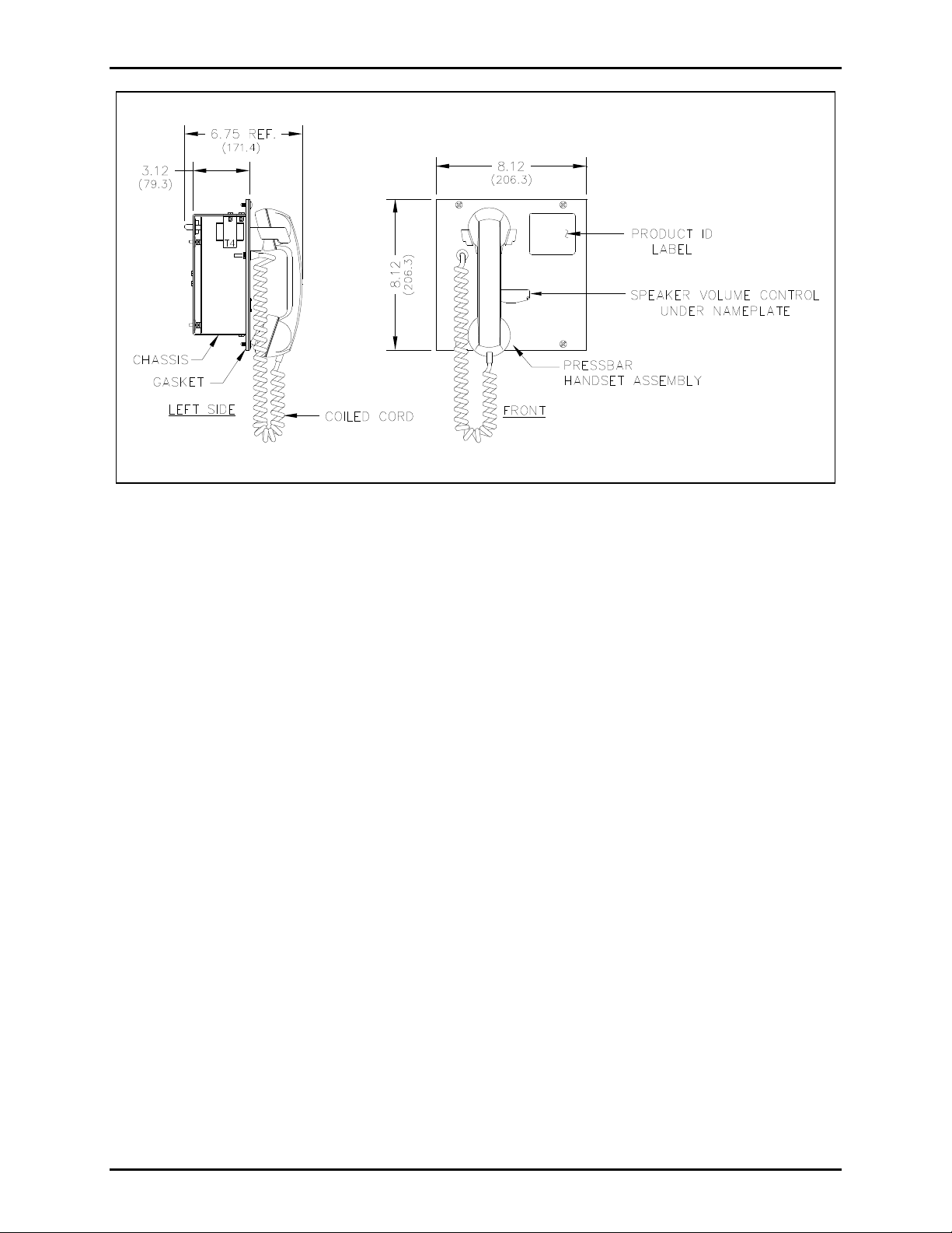
The Model 701-305 Handset/Speaker Amplifier plugs directly into the enclosure. The following figure
shows installation and adjustment details. Please refer to it when you are installing and adjusting the 701
Series amplifiers.
For continued IP 66 protection, torque setting for securing the amplifier to the enclosure should be 10 to
12 in-lbs. or 1.13 to 1.36 n-m.
GAI-Tronics Corporation 400 E. Wyomissing Ave. Mohnton, PA 19540 USA
610-777-1374 800-492-1212 Fax: 610-796-5954
ISIT WWW.GAI-TRONICS.COM FOR PRODUCT LITERATURE AND MANUALS
V
Page 2
Pub. 42004-365D
Model 701-305 Handset/Speaker Amplifier Page
2 of 5
Figure 1. Model 701-305 Outline Diagram
SCR Electrical Noise - Communications Alert
Please refer to Pub. 42004-139, 700 Series Page/Party® Systems, for system installation suggestions
where SCR power supply systems are used, or consult with a GAI-Tronics sales representative.
Operation
GAI-Tronics offers two types of Page/Party® systems: single-party (with one party line), and multi-party
(with five party lines allowing up to five simultaneous two-way conversations).
Single-Party: To initiate a call, lift the station handset and press the page button or press the handset
pressbar. Speak directly into the handset to make the page announcement. The paged individual lifts
the handset of a Page/Party
Multi-Party: First, select an available party line using the five-position selector switch. Then make
the page announcement as in single-party operation, remembering to indicate which party line is
being used. The paged individual then selects the indicated party line and lifts the handset for
two-way communication.
®
station for two-way communication over the party line.
f:\standard ioms - current release\42004 instr . manuals\42004-365d.doc
10/13
Page 3

Pub. 42004-365D
Model 701-305 Handset/Speaker Amplifier Page
3 of 5
Maintenance
The following adjustments are accessible through the rear chassis of the amplifier using a small standard
screwdriver. However, these levels have been factory-set for optimal performance. Do not adjust these
levels unless you have followed all the steps in the Troubleshooting section and are still not satisfied with
the station performance. Each adjustment is clearly labeled:
Microphone Gain: adjusts the gain level from the microphone signal to the page or party lines
Receiver Sidetone: the amount of signal transmitted from the microphone to the receiver of a handset
Receiver Volume: adjusts the gain level from a party line to the receiver
Speaker Amplifier Gain: adjusts the speaker volume; also accessible from the front panel
Fuses
WARNING
Do not remove fuses when energized. Replace with the same type and size fuse.
F1 = T.050A, 250V, 520mm, IEC 60127-2.
F2 = T.630A, 250V, 520mm, IEC 60127-2.
f:\standard ioms - current release\42004 instr . manuals\42004-365d.doc
10/13
Page 4

Pub. 42004-365D
Model 701-305 Handset/Speaker Amplifier Page
Troubleshooting
The following table lists some hints to aid technicians in troubleshooting:
Problem Solution
4 of 5
Any problem with station
performance occurs.
Integral speaker level requires
adjustment.
Outgoing conversation level
requires adjustment.
Incoming conversation level
requires adjustment.
Feedback/distortion (a hum or
buzz on the line) occurs during
all Page/Party
®
station
operation.
Review all the steps of the installation, ensuring that you have correctly
followed ALL steps. Check all the terminations on the board and in the
line balance assembly before proceeding to any other adjustments.
1. Adjust the volume control behind the nameplate on the front panel.
2. Replace the speaker or driver.
1. Adjust the microphone gain by removing the front cover of the
station and attaching a Model 10440 Series extension ribbon cable
between the connectors. Use a small standard screwdriver (
1
/8-inch
blade) to slowly turn potentiometer (R17) on the rear chassis of
amplifier until reaching the proper microphone gain.
2. Replace the handset microphone.
1. Use a small standard screwdriver to adjust the receiver volume
control on the rear of the amplifier using the extension ribbon cable
assembly as described above.
2. Replace the receiver element in the handset.
1. Adjust the receiver sidetone on the rear of the amplifier using the
ribbon cable assembly as described above.
2. The line may be improperly terminated. Inspect the system cable
for loose connections, shorts, and grounds. Line balance assembly
connections are critical.
3. Replace the line balance assembly.
Feedback occurs only during
page.
Sidetone (how the operator
hears his own voice) requires
adjustment.
Use the muting feature in the amplifier enclosure at the terminal blocks.
Connect the violet wire at terminal 8 to terminal 7.
1. Adjust the receiver sidetone at the amplifier, using the extension
ribbon cable as described above.
2. Check that the line balance assembly resistors are connected
properly. See GAI-Tronics Pub. 42004-139.
Crosstalk occurs. One or more system cable pairs may be improperly terminated.
Visually inspect the system cable connections for accidental crossing of
the cable pairs or grounds.
f:\standard ioms - current release\42004 instr . manuals\42004-365d.doc
10/13
Page 5

Pub. 42004-365D
Model 701-305 Handset/Speaker Amplifier Page
5 of 5
Specifications
Amplifier
Power requirements
Voltage .................................................................... 90–140 V ac range, 50/60 Hz, 120 V ac nominal
Power consumed: Zero/max. signal (12 watts) ................................ 10.5 VA, 5.3 W/58 VA, 29.5 W
Construction/Finish................................................................ 16-gauge cold-rolled steel/gray baked enamel
Handset
Microphone ........................................................................................................... Dynamic, noise-canceling
Receiver .................................................................................................... Dynamic, hearing aid compatible
Cable ...................................................................................................... Retractile, 6-foot extended Hytrel
Material ......................................................................................................................................... Gray ABS
External controls .................................................... Push-to-page handset pressbar and handset hookswitch
Handset Amplifier
Output level........................................................................................... 1.5 V
Output limiter ..................................................................................................................... 1.5 V
nominal into 33-ohm load
RMS
nominal
RMS
Gain ....................................................... 55 dB nominal (below limiter level); adjustable from 40 to 63 dB
Frequency response..................................................... 250–4000 Hz, +0/−3 dB ref. to 1 kHz (below AGC)
Distortion ..................................................................................................... 1.5% maximum THD @ 1 kHz
Controls .............................................................................. Microphone gain, receiver volume and sidetone
®
Speaker Amplifier
Output ................................................................................ 12 watts minimum with nominal supply voltage
Voltage gain ...................................................................................................... 26 dB maximum, adjustable
Frequency response........................................................................... 250–4,000 Hz, +0/−3 dB ref. to 1 kHz
Distortion ......................................................................................... 1% maximum THD @ 1 kHz, 12 watts
Input impedance .......................................................................................................... 50,000 ohms nominal
Controls .................................................................................. Speaker volume (adjusted through the access
hole behind the nameplate on the front panel)
General
Temperature range ......................................... −22º F to +158º F (−30º C to +70º C), operating and storage
Dimensions ............................................ 8.1 H 8.1 W 3.0 D inches (206 206 76 mm) behind panel
8.1 H 8.1 W 3.5 D inches (206 206 89 mm) front of panel
Shipping weight ..................................................................................................................... 6.8 lbs. (3.1 kg)
Approvals
NRTL listed ............................................................................................ Class I, Div. 2, Groups A, B, C, D;
Class II, Div. 2, Groups F, G;
Class III, Div. 2
Class I, Zone 2, Group IIC, Class II, Zone 22
when used with listed 702-006, 703-006, 703-007,
7325-106, or 7325-107 Enclosure
CE Mark
Replacement Parts
Contact GAI-Tronics for replacement part information.
f:\standard ioms - current release\42004 instr . manuals\42004-365d.doc
10/13
Page 6

Warranty
Equipment. GAI-Tronics warrants for a period of one (1) year from the date of shipment, that any
GAI-Tronics equipment supplied hereunder shall be free of defects in material and workmanship, shall
comply with the then-current product specifications and product literature, and if applicable, shall be fit
for the purpose specified in the agreed-upon quotation or proposal document. If (a) Seller’s goods prove
to be defective in workmanship and/or material under normal and proper usage, or unfit for the purpose
specified and agreed upon, and (b) Buyer’s claim is made within the warranty period set forth above,
Buyer may return such goods to GAI-Tronics’ nearest depot repair facility, freight prepaid, at which time
they will be repaired or replaced, at Seller’s option, without charge to Buyer. Repair or replacement shall
be Buyer’s sole and exclusive remedy. The warranty period on any repaired or replacement equipment
shall be the greater of the ninety (90) day repair warranty or one (1) year from the date the original
equipment was shipped. In no event shall GAI-Tronics warranty obligations with respect to equipment
exceed 100% of the total cost of the equipment supplied hereunder. Buyer may also be entitled to the
manufacturer’s warranty on any third-party goods supplied by GAI-Tronics hereunder. The applicability
of any such third-party warranty will be determined by GAI-Tronics.
Services. Any services GAI-Tronics provides hereunder, whether directly or through subcontractors,
shall be performed in accordance with the standard of care with which such services are normally
provided in the industry. If the services fail to meet the applicable industry standard, GAI-Tronics will
re-perform such services at no cost to buyer to correct said deficiency to Company's satisfaction provided
any and all issues are identified prior to the demobilization of the Contractor’s personnel from the work
site. Re-performance of services shall be Buyer’s sole and exclusive remedy, and in no event shall GAITronics warranty obligations with respect to services exceed 100% of the total cost of the services
provided hereunder.
Warranty Periods. Every claim by Buyer alleging a defect in the goods and/or services provided
hereunder shall be deemed waived unless such claim is made in writing within the applicable warranty
periods as set forth above. Provided, however, that if the defect complained of is latent and not
discoverable within the above warranty periods, every claim arising on account of such latent defect shall
be deemed waived unless it is made in writing within a reasonable time after such latent defect is or
should have been discovered by Buyer.
Limitations / Exclusions. The warranties herein shall not apply to, and GAI-Tronics shall not be
responsible for, any damage to the goods or failure of the services supplied hereunder, to the extent
caused by Buyer’s neglect, failure to follow operational and maintenance procedures provided with the
equipment, or the use of technicians not specifically authorized by GAI-Tronics to maintain or service the
equipment. THE WARRANTIES AND REMEDIES CONTAINED HEREIN ARE IN LIEU OF AND
EXCLUDE ALL OTHER WARRANTIES AND REMEDIES, WHETHER EXPRESS OR IMPLIED BY
OPERATION OF LAW OR OTHERWISE, INCLUDING ANY WARRANTIES OF
MERCHANTABILITY OR FITNESS FOR A PARTICULAR PURPOSE.
Return Policy
If the equipment requires service, contact your Regional Service Center for a return authorization number
(RA#). Equipment should be shipped prepaid to GAI-Tronics with a return authorization number and a
purchase order number. If the equipment is under warranty, repairs or a replacement will be made in
accordance with the warranty policy set forth above. Please include a written explanation of all defects to
assist our technicians in their troubleshooting efforts.
Call 800-492-1212 (inside the USA) or 610-777-1374 (outside the USA) for help identifying the
Regional Service Center closest to you.
(Rev. 10/06)
 Loading...