

Page 1

Pub. 42004-311A
GAI-TRONICS® CORPORATION
A HUBBELL COMPANY
Model 701-202
Handset/Speaker Amplifier
Confidentiality Notice
This manual is pr ovided s olely as a n op erat ional, installation, and maintenance guide and contains sens itive
bus ines s and t echnic al infor ma tion tha t is confident ial and prop rieta ry to GAI - Tr onic s. GAI- Tr onic s retains
all intellectual prop erty a nd other r ights in or to the information contained herein, and s uch infor ma tion may
only be used in connection with t he op erat ion of your GAI-T ronics produ c t or s ystem. This manu al may not
be disclos ed in any form, in whole or in pa rt, direct ly or indirectly, t o any third party.
General Information
The Model 701-202 Handset/Speaker Amplifier includes a new printed circuit board assembly (PCBAs)
with alternat e el ectronic components. This ampl i fier uses a new PC B A for repl acement purposes. See th e
Repla c ement P arts section for det ails.
®
The Model 701-202 Handset/Speaker Amplifier is an important component of the 700 Series Page/Party
syst em, an industrial communications system designed to be b oth dur able a nd f l exible. GAI- Tr onic s offers
a wide variety of c onf iguration options to solve challenging application problems.
CAUTION
Do not install this equipment in hazardous areas or areas other than those on the equipment approval
list in the Specifications section. Such installation may cause a safety hazard and consequent injury
or property damage.
Installation
The Model 701-202 Handset/Speaker Amplifier is a plug-in amplifier that mates directly with the 702, 703,
732, 733, 7325, and 7335 Series Amplifier Enclosures. Install the handset/speaker amplifier by plugging it
directly into the amplifier enclosure.
GAI-Tronics Corporation P.O. Box 1060, Reading, PA 19607-1060 USA
610-777-1374 800-492-1212 Fax : 610-796-5954
ISIT WWW.GAI-TRONICS.COM FOR PRODUCT LITERATURE AND MANUALS
V
Page 2
Pub. 42004-311A
Model 701-202 Handset/S peak er A mplifier Page: 2 of 5
Operation
GAI-Tronics offer s two types of P age/P arty® syst ems: Page/ Single-Part y ( with one party line), and
Pa ge/ Mult i- Party (with five pa rty lines allowing up to five simult aneous two-way c onversa tions).
• Page/Single-Party: To initiate a c all, the lift the stat ion handset and press the p age but ton or t he
handset pr es sba r. Speak directly into the handset, ma ke your page annou nc ement. The p aged
individual lif ts t he ha ndset of a Pa ge/ Party
• Page/Multi-Party: Firs t select a n available pa rty line with the five-posit ion selector switch. Then make
your page a nnouncement as in single-pa rty op erat ion, remembering t o indic ate the p arty line being
used. The pa ged individu al then selects the indicated part y line and lifts the handset for two-way
communication.
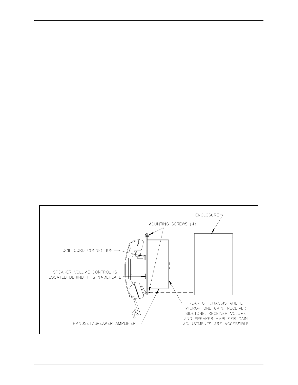
The following adjustments are accessible through the rear chassis of the amplifier using a small standard
scr ewdriver. However, these levels have b een factory-set f or opt i ma l performance. D o not adju st these
levels unless you have followed all the steps in the Troubleshooting section and are still not satisfied wit h
the station p erforma nc e. Eac h adjustment is clearly labeled:
• Microphone Gain: adjusts the ga in level from the microphone s i gnal to the p age or p arty lines
®
station for two-way communica tion over t he p arty line.
• Receiver Sid et o n e: the amount of signal transmitted f rom the microp hone to the receiver of a handset
• Receiver Volume: a djusts the gain level fr om a party line to the receiver
• Speaker Amplifier Gain: adjusts the speaker volume; a lso acces sible fr om t he front p anel
Please refer to the figure below when installing and adjusting the Model 701-202 Handset/Speaker
Amplifier.
Figure 1. I nsta llation and Adjustment Deta ils
\\s_eng\gtc proddoc s \ s t andard iom s - current release\42004 inst r. m anuals \ 42004-311a. doc
11/03
Page 3

Pub. 42004-311A
Model 701-202 Handset/S peak er A mplifier Page: 3 of 5
Maintenance
Troubleshooti ng
The following t able lists some hints to aid technicians in trou bleshooting.
Problem Solution
Any problem with station
perf ormance occ urs .
Integral sp eaker level requires
adjustment.
Out going c onversation level
requires adju stment.
Incoming convers ation level
requires adju stment.
Feedback/dist ortion ( a hum or
buzz on the line) occurs
®
during all Page/Party
station
operation.
Review all the s teps of the installat ion, ensuring tha t you ha ve correctly
followed ALL s teps. Check a ll the termina tions on the b oard and in the
line balance as sembly before proceeding to a ny other a djustments.
1. Adjust the volume contr ol behind the namepla te on the fr ont pa nel.
2. Rep lac e the s peak er or dr i v er.
1. Adjust the microphone gain by r emoving the f ront cover of the s tat ion
and attaching a Model 10440 Series extension ribbon cable between
the connectors. Use a small st andard screwdriver (
1
/8-inch blade), to
slowly tu rn potent iometer (R17) on the r ear chassis of amplif ier until
reaching the proper microphone gain.
2. Replace the ha ndset micr ophone.
1. Use a small standard screwdriver to adjust the receiver volume
contr ol on the rear of t he a mp lif ier using the extension ribbon cable
assembly as des c ribed a bove.
2. Rep lac e the receiver element in t he h andset.
1. Adjust the receiver s i det one on t he rear of the amplifier using t he
rib bon cab l e assembly as described above.
2. The line ma y be improp erly ter mi n ated . In spec t th e system cable for
loose connections, s horts , and grounds. Line balanc e assembly
connections are critical.
3. Rep lac e the lin e balance assemb l y .
Feedba c k oc c urs only during
page.
Sidetone ( how the operator
hears his own voice) requir es
adjustment.
Use t h e mutin g feature in the a mplifi er enclosure at the t erminal bl o cks
Connect the violet wire at T B 1-8 t o TB1- 7.
1. Adjust the receiver s i det one at the amplifier, using t he extension
rib bon cable as des c ribed above.
2. Check that t he line balance assembly resistors are connected prop erly.
(See GAI-Tronics Publication 42004-139)
Crosstalk occurs. One or more system cable pairs may be improperly terminated. Visually
inspect the sys tem cable connections for ac c idental cross ing of the ca ble
pairs or grou nds.
\\s_eng\gtc proddoc s \ s t andard iom s - current release\42004 inst r. m anuals \ 42004-311a. doc
11/03
Page 4

Pub. 42004-311A
Model 701-202 Handset/S peak er A mplifier Page: 4 of 5
Specifications
Amplifier
Voltage............................................................................ 90/140 V ac range, 50/60 Hz, 120 V ac nominal
Power Consumed: Zero/max. signal (12 watts).............................................. 10 VA, 4.5 W/50 VA, 27 W
Construction/Finish............................................................... 16-gauge cold-rolled steel/gray baked enamel
Handset
Microphone ........................................................................................................Dynamic, noise-canceling
Receiver........................................................................Dynamic, hearing aid compatible per FCC Part 68
Cable.........................................................................................................Retractile, 6-foot ext ended P VC
Material.....................................................................................................................................Gray ABS
External controls.........................................................Push-to-page handset pressbar, handset hook-switch
Handset Amplifier
Output level......................................................................................... 1.5 V
Output limiter................................................................................................................ 1.5 V
nominal into 3 3-ohm load
RMS
nominal
RMS
Gain.................................................................................................. 55 dB nominal (below limiter level);
adjustable from 40 to 63 dB
Frequency response..............................................................................................250-4000 Hz, +/- 1.5 dB
Distortion.............................................................................................. 1.5% maximum THD @ 1000 Hz
Controls..............................................................................Microphone gain, receiver volume and sidetone
Speaker Amplifier
Output......................................................................................12 watts min., with nominal supply voltage
Voltage gain ............................................................................................................ 26 dB max, adjustable
Frequency response.........................................................................250-4,000 Hz, +0, - 3 dB ref. to 1 kHz
Distortion.........................................................................................1% max. THD @ 1,000 Hz, 12 watts
Input impedance.............................................................................................................50,000 ohms nom.
Controls................................................................................. Speaker volume (adjusted through the access
hole behind the nameplate on the front p anel)
General
Temperature range (Operating/Storage).............................................. -22º F to +158º F (-30º C to +70º C)
Dimensions..............................................8.1 H × 8.1 W × 3 D inches (20.6 × 20.6 × 7.6 cm) behind panel
8.1 H × 8.1 W × 3.5 D inches (20.6 × 20.6 × 8.9 cm) fr ont of panel
Shipping Weight................................................................................................................ 6. 8 lbs. (3.1 kg)
Approvals
NRTL Listed for USA and Canada:..............................Div. 2, Class I, Groups A, B, C, D when used with
GAI-Tronics Listed 702 or 703 Series 120 V ac enclosures.
Div. 2, Class I, Groups A, B, C, D; Div. 2, C lass II, Group F and G;
Div. 2, Class III when used with listed GAI-Tronics
Model 733, 732, 7325, or 7335 Series 120 V ac enclosures
\\s_eng\gtc proddoc s \ s t andard iom s - current release\42004 inst r. m anuals \ 42004-311a. doc
11/03
Page 5

Pub. 42004-311A
Model 701-202 Handset/S peak er A mplifier Page: 5 of 5
REPLACEMENT PARTS
Part No. Description
10105-007 Handset Assembly
13204-002 Receiver Cap
12511-001 Dynamic Transmitter and Cap
12550-001 Receiver Assembly and PCBA
51008-003 Pressbar Switch Kit
12514-007 6-foot PVC Cord and Bushing
12514-008 15-foot PVC Cord and Bushing
12514-009 25-foot PVC Cord and Bushing
12514-004 6-foot Hytrel Cord and Bushing
12514-005 15-foot Hytrel Cord and Bushing
12514-006 25-foot Hytrel Cord and Bushing
69701-007 PCBA
12523-001 GAI-Tronics Nameplate Kit
12601-001 PCBA Standoffs (10)
46101-012 Hardware Kit
12519-002 Hook Assembly
12530-001 Transformer/ Conn. Subassembly
25210-005 Cell Gasket
10440-002 16-pin ribbon cable connector
61512-007 Harness Assembly Switch
12604-001 0.7 amp (10 pack)
12604-002
1
/16
amp (10 pack)
\\s_eng\gtc proddoc s \ s t andard iom s - current release\42004 inst r. m anuals \ 42004-311a. doc
11/03
Page 6

Warranty
Equipment. GAI-Tronics warrants for a period of one (1) year from the date of shipment, that any
GAI-Tronics equipment supplied hereunder shall be free of defects in material and workmanship, shall
comply with the then-current product specifications and product literature, and if applicable, shall be fit
for the purpose specified in the agreed-upon quotation or proposal document. If (a) Seller’s goods prove
to be defective in workmanship and/or material under normal and proper usage, or unfit for the purpose
specified and agreed upon, and (b) Buyer’s claim is made within the warranty period set forth above,
Buyer may return such goods to GAI-Tronics’ nearest depot repair facility, freight prepaid, at which time
they will be repaired or replaced, at Seller’s option, without charge to Buyer. Repair or replacement shall
be Buyer’s sole and exclusive remedy. The warranty period on any repaired or replacement equipment
shall be the greater of the ninety (90) day repair warranty or one (1) year from the date the original
equipment was shipped. In no event shall GAI-Tronics warranty obligations with respect to equipment
exceed 100% of the total cost of the equipment supplied hereunder. Buyer may also be entitled to the
manufacturer’s warranty on any third-party goods supplied by GAI-Tronics hereunder. The applicability
of any such third-party warranty will be determined by GAI-Tronics.
Services. Any services GAI-Tronics provides hereunder, whether directly or through subcontractors,
shall be performed in accordance with the standard of care with which such services are normally
provided in the industry. If the services fail to meet the applicable industry standard, GAI-Tronics will
re-perform such services at no cost to buyer to correct said deficiency to Company's satisfaction provided
any and all issues are identified prior to the demobilization of the Contractor’s personnel from the work
site. Re-performance of services shall be Buyer’s sole and exclusive remedy, and in no event shall GAITronics warranty obligations with respect to services exceed 100% of the total cost of the services
provided hereunder.
Warranty Periods. Every claim by Buyer alleging a defect in the goods and/or services provided
hereunder shall be deemed waived unless such claim is made in writing within the applicable warranty
periods as set forth above. Provided, however, that if the defect complained of is latent and not
discoverable within the above warranty periods, every claim arising on account of such latent defect shall
be deemed waived unless it is made in writing within a reasonable time after such latent defect is or
should have been discovered by Buyer.
Limitations / Exclusions. The warranties herein shall not apply to, and GAI-Tronics shall not be
responsible for, any damage to the goods or failure of the services supplied hereunder, to the extent
caused by Buyer’s neglect, failure to follow operational and maintenance procedures provided with the
equipment, or the use of technicians not specifically authorized by GAI-Tronics to maintain or service the
equipment. THE WARRANTIES AND REMEDIES CONTAINED HEREIN ARE IN LIEU OF AND
EXCLUDE ALL OTHER WARRANTIES AND REMEDIES, WHETHER EXPRESS OR IMPLIED BY
OPERATION OF LAW OR OTHERWISE, INCLUDING ANY WARRANTIES OF
MERCHANTABILITY OR FITNESS FOR A PARTICULAR PURPOSE.
Return Policy
If the equipment requires service, contact your Regional Service Center for a return authorization number
(RA#). Equipment should be shipped prepaid to GAI-Tronics with a return authorization number and a
purchase order number. If the equipment is under warranty, repairs or a replacement will be made in
accordance with the warranty policy set forth above. Please include a written explanation of all defects to
assist our technicians in their troubleshooting efforts.
Call 800-492-1212 (inside the USA) or 610-777-1374 (outside the USA) for help identifying the
Regional Service Center closest to you.
(Rev. 10/06)
 Loading...