

Page 1

Pub. 42004-729L2A
GAI-TRONICS® CORPORATION
A HUBBELL COMPANY
69609-001
®
Dual Page/Party
Confidential ity Notice
This manual is provided solely as an operational, installation, and maintenance guide and contains
sensitive business and technical information that is confidential and proprietary to GAI-Tronics.
GAI-Tronics retains all intellectual property and other rights in or to the information contained herein,
and such information may only be used in connection with the operation of your GAI-Tronics product or
system. This manual may not be disclosed in any form, in whole or in part, directly or indirectly, to any
third party.
General Information
NOTE: If the 69609-001 Dual Page/Party
system, the GAI-Tronics Service Department must be contacted to modify the system configuration. If
the Dual PPI is being used as a replacement part, proceed as described herein.
®
Interface (Dual PPI) is being added to an existing installed
Interface PCBA
®
The 69609-001 Dual PPI is a printed circuit board assembly (PCBA) used to interface Page/Party
equipment to the 69254 Series or 69440 Series Master Control Unit (MCU). The Dual PPI PCBA is
housed in a 10457 Series Card Rack with the MCU and other associated PCBAs. The Dual PPI will
support up to two Page/Party
®
zones, referred to as “Zone A” and “Zone B.”
field
How to Use the Assembly
The 69609-001 Dual PPI includes the following features and capabilities:
• Communication with external GAI-Tronics field devices via FSK over the 33-ohm page line
• Supports party line 1 and party line 2 on/off hook detection
• Provides ground fault detection on the page line and party line 1
• Provides for fail-safe path
• Self check path diagnostics
• Performs audio switching to transmit from the 33-ohm page line to one of two 1000-ohm differential
backplane page resources
• Allows page line audio to drive a differential page monitor bus on the backplane
• Allows party line switching from the 33-ohm party lines to the 33-ohm backplane
• Receives one external dry contact closure input for each Page/Party
• Provides one output to drive an external relay at each Page/Party
®
zone
®
zone for special applications
GAI-Tronics Corporation 400 E. Wyomissing Ave. Mohnton, PA 19540 USA
610-777-1374 800-492-1212 Fax: 610-796-5954
V
ISIT WWW.GAI-TRONICS.COM FOR PRODUCT LITERATURE AND MANUALS
Page 2

Pub. 42004-729L2A
69609-001 Dual Page/Party
®
Interface PCBA Page: 2 of 16
IMPORTANT NOTE:
The Dual PPI does NOT support the following legacy features contained in the 69255-001 Page/Party
®
Interface (PPI) PCBA:
• “Control Area PPI” Board Type. The Dual PPI may only report as a “Field Area PPI” or as a “Dual
PPI”
• RS-485 communication line
• Party line 1 supervision via DTMF tone detection
Hardware Configuration
Switch and Jumper Settings
Overview
Several switch and jumper settings are required for proper operation of the Dual PPI. The following
settings are set during the system commissioning and programming and should not be changed. If
replacing an existing Dual PPI for maintenance purposes, be sure to replicate the switch and jumper
setting of the card being replaced. Refer to Figure 1 on page 10 for the switch and jumper locations.
Board Address Rotary Switch (SW1) Settings
This switch is used in conjunction with SW4 Position 1 to determine the board addresses used by the
®
MCU to access the Dual PPI. Since the Dual PPI provides access to two distinct Page/Party
zones, the
Dual PPI occupies two separate board addresses – one for Zone A and one for Zone B (assuming that
Zone B is enabled). The board addresses for Zone A and Zone B are defined below (expressed as
hexadecimal values):
Zone A Board Address
Board Address Example:
2 A 0
/ / /----------Always zero
Equals 2 when SW4 Position 1 is OPEN--------------/ /
Equals 0 when SW4 Position 1 is CLOSED----------/ /
/
Set by SW1----------------------------------------------------------------/
Zone B Board Address
Board Address Example:
3 A 0
/ / /----------Always zero
Equals 3 when SW4 Position 1 is OPEN--------------/ /
Equals 1 when SW4 Position 1 is CLOSED----------/ /
/
Set by SW1----------------------------------------------------------------/
Please note that if Zone B is disabled (SW4 Position 2 is CLOSED), then the Dual PPI will only occupy
the Zone A board address (the Zone B board address would then be available for use by other cards in the
card rack).
f:\standard ioms - current release\42004 instr. manuals\42004-729l2a.doc
09/09
Page 3

®
69609-001 Dual Page/Party
Interface PCBA Page: 3 of 16
Board ID Rotary Switches (SW2 and SW3) Settings
Pub. 42004-729L2A
These switches are used in conjunction with SW4 Positions 4 and 6 to determine the Board ID values for
Zone A and Zone B. Since the Dual PPI provides access to two distinct Page/Party
®
zones, the Dual PPI
provides two separate Board ID values – one for Zone A and one for Zone B (assuming that Zone B is
enabled). The Board ID values for Zone A and Zone B are defined below (expressed as hexadecimal
values):
Zone A Board ID
Board ID Example:
0 1
/ /
Equals 0 when SW4 Position 4 is OPEN--------------/ /
Equals 1 when SW4 Position 4 is CLOSED----------/ /
/
Set by SW2----------------------------------------------------------------/
Zone B Board ID
Board ID Example:
0 3
/ /
Equals 0 when SW4 Position 6 is OPEN--------------/ /
Equals 1 when SW4 Position 6 is CLOSED----------/ /
/
Set by SW3----------------------------------------------------------------/
Please note that SW4 Positions 4 and 6 (Extended Board ID A/Extended Board ID B) will only function
when SW4 Position 3 (Board Type Select) is in the OPEN position (“Dual PPI” Board Type is selected.)
Otherwise, the upper hexadecimal digit of the Board ID values for Zone A and Zone B will be forced to
®
be “0”. Also, note that each Page/Party
zone associated with a given card rack must be assigned a
unique Board ID value to allow it to be clearly identified by the MCU. For sake of simplicity, the Board
ID values are typically set to match the zone numbers as defined in the system.
f:\standard ioms - current release\42004 instr. manuals\42004-729l2a.doc
09/09
Page 4
Pub. 42004-729L2A
69609-001 Dual Page/Party
®
Interface PCBA Page: 4 of 16
Board Configuration DIP Switch (SW4) Settings
Board Configuration DIP Switch SW4 contains eight positions that control various aspects of board
operation in the associated system. The function of each position is detailed below.
Position 1: Board Address Range Select
This switch is used in conjunction with rotary switch SW1 to determine the board addresses used by the
MCU to access the Dual PPI. Refer to the “Board Address Rotary Switch (SW1) Settings” section on
page 2 for more information.
Position 2: Zone B Disable
This switch may be used to “hide” Zone B from the MCU. This feature may be desirable in cases where
only one of the two available zones on the Dual PPI will be utilized by the system. Set the switch
according to the following table:
OPEN
CLOSED
Zone B is Enabled.
Zone B is Disabled (not visible to the MCU)
Position 3: Board Type Select
This switch determines the Board Type that the Dual PPI will report to the MCU by both Zone A and
®
Zone B. The Dual PPI has the ability to either report as a Page/Party
®
Page/Party
OPEN
CLOSED
Interface (Dual PPI). Set the switch according to the following table:
“Dual PPI” Board Type is selected.
“PPI” Board Type is selected.
Interface (PPI), or as a Dual
OTE: Upon initial release of the Dual PPI Card, always set switch position 3 to the closed position for
N
“PPI” board type. The “Dual PPI” board type is reserved for future use pending release of compatible
MCU firmware.
f:\standard ioms - current release\42004 instr. manuals\42004-729l2a.doc
09/09
Page 5
®
69609-001 Dual Page/Party
Position 4: Extended Board I D A
Interface PCBA Page: 5 of 16
Pub. 42004-729L2A
This switch is used in conjunction with rotary switch SW2 to determine the Board ID value for Zone A.
Refer to the “Board ID Rotary Switches (SW2 and SW3) Settings” section on page 3 for more
information.
Position 5: FSK Test Mode Enable A
This switch may be used to force activation of the FSK carrier signal at Zone A. A continuous alternating
1-0 data pattern at 2400 bps is produced. This switch must be left in the OPEN position for normal
system operation. The following table defines the operation of this switch:
OPEN
FSK Test Mode for Zone A is Disabled (Must be left in this position for normal
operation.)
CLOSED
FSK Test Mode for Zone A is Enabled.
Position 6: Extended Board ID B
This switch is used in conjunction with rotary switch SW3 to determine the Board ID value for Zone B.
Refer to the “Board ID Rotary Switches (SW2 and SW3) Settings” section on page 3 for more
information.
Position 7: FSK Test Mode Enable B
This switch may be used to force activation of the FSK carrier signal at Zone B. A continuous alternating
1-0 data pattern at 2400 bps is produced. This switch must be left in the OPEN position for normal
system operation. The following table defines the operation of this switch:
OPEN
FSK Test Mode for Zone B is Disabled (Must be left in this position for normal
operation.)
CLOSED
FSK Test Mode for Zone B is Enabled.
Position 8: Reserved
This switch is currently unused by the Dual PPI and should be left in the OPEN position.
f:\standard ioms - current release\42004 instr. manuals\42004-729l2a.doc
09/09
Page 6
Pub. 42004-729L2A
69609-001 Dual Page/Party
®
Interface PCBA Page: 6 of 16
Page Balance Select (Zone A) Jumper (P6) Settings
This jumper allows the Dual PPI’s internal page balance for Zone A to be disabled in cases where use of a
page balance external to the Dual PPI is desired. Note that if an external page balance is used, however, it
must be located in proximity to the card rack. In general, this jumper should be left in the “EN” position
(internal page balance enabled). Set the jumper according to the following table:
EN
DIS
Internal Page Balance is Enabled (Should be left in this position for most installations.)
Internal Page Balance is Disabled.
NOTE: If this jumper is set to the “DIS” position, then the Page Balance adjustment for Zone A will have
no effect.
Page Balance Select (Zone B) Jumper (P7) Settings
This jumper allows the Dual PPI’s internal page balance for Zone B to be disabled in cases where use of a
page balance external to the Dual PPI is desired. Note that if an external page balance is used, however, it
must be located in proximity to the card rack. In general, this jumper should be left in the “EN” position
(internal page balance enabled). Set the jumper according to the following table:
EN
DIS
Internal Page Balance is Enabled (Should be left in this position for most installations.)
Internal Page Balance is Disabled.
NOTE: If this jumper is set to the “DIS” position, then the Page Balance adjustment for Zone B will have
no effect.
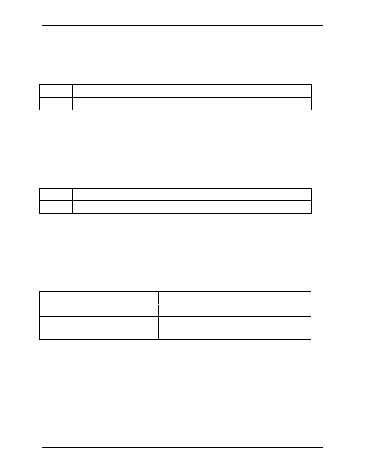
Monitor Bus Transmit/Receive (Zone A) Jumper (P8, P9, P12) Settings
These three jumpers may allow Zone A page line audio to drive the monitor bus. Alternatively, these
jumpers may allow audio on the monitor bus to drive the Zone A page line. A third option that these
jumpers provide is complete isolation between the monitor bus and the Zone A page line. These three
options are summarized in the following table:
Option P8 Setting P9 Setting P12 Setting
Isolation DIS DIS DIS
Zone A Page Audio → Monitor Bus EN EN DIS
Monitor Bus → Zone A Page line DIS DIS EN
f:\standard ioms - current release\42004 instr. manuals\42004-729l2a.doc
09/09
Page 7

Pub. 42004-729L2A
69609-001 Dual Page/Party
®
Interface PCBA Page: 7 of 16
Monitor Bus Transmit/Receive (Z one B) Jumper (P10, P11, P13) Settings
These three jumpers may allow Zone B page line audio to drive the monitor bus. Alternatively, these
jumpers may allow audio on the monitor bus to drive the Zone B page line. A third option that these
jumpers provide is complete isolation between the monitor bus and the Zone B page line. These three
options are summarized in the following table:
Option P10 Setting P11 Setting P13 Setting
Isolation DIS DIS DIS
Zone B Page Audio → Monitor Bus EN EN DIS
Monitor Bus → Zone B Page line DIS DIS EN
Tips on Using a Dual PP I to Replace a Single 69255-001 PP I Board
• When using a Dual PPI to replace a single 69255-001 PPI board, the Zone A portion of the Dual PPI
should be used (Zone B of the Dual PPI will be disabled.)
• When setting the board address for the Dual PPI, use the following conversion table as a guide:
Switch on
Dual PPI
Equivalent Switc h
on PPI
Notes
SW1 S1 Assigns middle nibble of board address
Refer to the “Board Address Rotary Switch (SW1) Settings” section on page 2 for more information
regarding Dual PPI board address assignment.
• When setting the Board ID values for the Dual PPI, use the following conversion table as a guide:
Switch on
Dual PPI
Equivalent Switc h
on PPI
Notes
SW2 S2 Assigns Board ID for Zone A
SW3 None Assigns Board ID for Zone B
Note that in this case, the position of SW3 is unimportant and will be ignored by the system. Refer to the
“Board ID Rotary Switches (SW2 and SW3) Settings” section on page 3 for more information regarding
Dual PPI Board ID values assignment.
f:\standard ioms - current release\42004 instr. manuals\42004-729l2a.doc
09/09
Page 8

®
69609-001 Dual Page/Party
• The following settings for SW4 are recommended for most installations:
Interface PCBA Page: 8 of 16
Switch (SW4) Setting
Position 1 OPEN
Pub. 42004-729L2A
Position 2
CLOSED
Position 3 CLOSED
Position 4 OPEN
Position 5 OPEN
Position 6 OPEN
Position 7 OPEN
Position 8 OPEN
Note that Position 2 of SW4 must be CLOSED in order to disable Zone B. Refer to the “Board
Configuration DIP Switch (SW4) Settings” section on page 4 for more information on these settings.
• For most installations, the Page Balance Select (P6 and P7) jumpers should be set to the “EN”
position (internal page balance enabled.)
• When setting the Monitor Bus Transmit/Receive jumpers for the Dual PPI, use the following
conversion table as a guide:
Jumper(s) on
Dual PPI
Equivalent Jump er(s)
on PPI
Notes
P8/P9 J6/J8/J11/J12 Zone A Page Audio → Monitor Bus
P12 J9/J10 Monitor Bus → Zone A Page Line
NOTE: Jumpers P10, P11, and P13 should all be placed in the “DIS” position in this case.
Tips on Using a Dual PPI to Replace Two 69255-001 PPI Boards
• The first step that should be performed when using a Dual PPI to replace two 69255-001 PPI boards
is to decide which 69255-001 PPI board will be mapped to Zone A of the Dual PPI and which will be
mapped to Zone B. Hereafter, based on this mapping, the two 69255-001 PPI boards will be referred
to as the “Zone A PPI” and “Zone B PPI.”
• When setting the board address for the Dual PPI, use the following conversion table as a guide:
Switch on
Dual PPI
SW1 S1 on either Zone A PPI or
Equivalent Switc h
on PPI
Notes
Assigns middle nibble of board address
Zone B PPI
f:\standard ioms - current release\42004 instr. manuals\42004-729l2a.doc
09/09
Page 9

Pub. 42004-729L2A
69609-001 Dual Page/Party
®
Interface PCBA Page: 9 of 16
It is important to note that the Dual PPI occupies two distinct board addresses. Therefore, the installer
must ensure that these two board addresses do not conflict with any other cards installed in the card rack.
To prevent this, it may be necessary to change the board address of another card in the card rack. Refer to
the “Board Address Rotary Switch (SW1) Settings” section on page 2 for more information regarding
Dual PPI board address assignment.
• When setting the Board ID values for the Dual PPI, use the following conversion table as a guide:
Switch on
Dual PPI
Equivalent Switc h
on PPI
Notes
SW2 S2 on “Zone A PPI” Assigns Board ID for Zone A
SW3 S2 on “Zone B PPI” Assigns Board ID for Zone B
Refer to the “Board ID Rotary Switches (SW2 and SW3) Settings” section on page 3 for more
information regarding Dual PPI Board ID values assignment.
• The following settings for SW4 are recommended for most installations:
Switch (SW4) Setting
Position 1 OPEN
Position 2 OPEN
Position 3 CLOSED
Position 4 OPEN
Position 5 OPEN
Position 6 OPEN
Position 7 OPEN
Position 8 OPEN
Refer to the “Board Configuration DIP Switch (SW4) Settings” section on page 4 for more information
on these settings.
• For most installations, the Page Balance Select (P6 and P7) jumpers should be set to the “EN”
position (internal page balance enabled.)
• When setting the Monitor Bus Transmit/Receive jumpers for the Dual PPI, use the following
conversion table as a guide:
Jumper(s) on
Dual PPI
Equivalent Jump er(s)
on PPI
Notes
P8/P9 J6/J8/J11/J12 on Zone A PPI Zone A Page Audio → Monitor Bus
P12 J9/J10 on Zone A PPI Monitor Bus → Zone A Page Line
P10/P11 J6/J8/J11/J12 on Zone B PPI Zone B Page Audio → Monitor Bus
P13 J9/J10 on Zone B PPI Monitor Bus → Zone B Page Line
f:\standard ioms - current release\42004 instr. manuals\42004-729l2a.doc
09/09
Page 10

69609-001 Dual Page/Party
®
Interface PCBA Page: 10 of 16
Pub. 42004-729L2A
Figure 1. 69609-001 PCBA
f:\standard ioms - current release\42004 instr. manuals\42004-729l2a.doc
09/09
Page 11

69609-001 Dual Page/Party
Interfaces
®
Interface PCBA Page: 11 of 16
Pub. 42004-729L2A
Figure 2. 69609-001 Interfaces
All field device interfaces are provided through P2 on the 69609-001 Dual PPI PCBA and include the
following connections for each of the two available Page/Party
®
zones:
• Page line
• Party line 1
• Party line 2
• Contact closure input
• External relay control output
OTE: Field connections for Zone A are provided at the card rack’s lower D-subminiature connector,
N
while field connections for Zone B are provided at the card rack’s upper D-subminiature connector.
f:\standard ioms - current release\42004 instr. manuals\42004-729l2a.doc
09/09
Page 12

®
69609-001 Dual Page/Party
Interface PCBA Page: 12 of 16
Installation /Replacement
WARNING: Failure to observe warnings may result in equipment damage.
WARNING:
Observe
Precautions For
Handling Electrostatic
Sensitive Devices
WARNING:
Disconnect power to
the card rack prior to
installation
Pub. 42004-729L2A
1. Remove the 69609-001 Dual PPI from its carton. Be sure to check that power is disconnected to the
card rack assembly prior to replacement.
2. Verify that the switch and jumper settings described in the Switch and Jumper Settings section are set
in accordance with the instructions in your system manual.
3. Remove existing Dual PPI from card rack assembly.
4. Install the replacement Dual PPI as described below.
Align the PCBA into the upper and lower tracks of the assigned slot. Slide the PCBA towards the
rear of the card rack until it comes in contact with the backplane connector. Firmly press on the front
bezel until the PCBA is seated. Secure to the card rack by tightening the two screws located on the
front bezel (See Figure 1).
5. Apply power to card rack assembly.
6. After a brief delay, the On Line LEDs on the Dual PPI will illuminate for all configured zones.
7. The RTS LEDs flash continuously if SmartSeries stations are configured to communicate with the
Dual PPI.
8. The EOL FAULT LEDs should NOT illuminate. These LEDs only illuminate when an End-of-Line
(EOL) device is not responding to the Dual PPI.
9. The GND FAULT LEDs should NOT illuminate. These LEDs only illuminate when a ground fault is
present on the page line or party line 1.
Zone A or Zone B
LED
Condition
EOL Fault An end-of-line station is not responding
Ground Fault One conductor of either the page line or Party Line 1 is grounded
On Line Page/Party® zone is recognized by the MCU
RTS Data Communication request to send
f:\standard ioms - current release\42004 instr. manuals\42004-729l2a.doc
09/09
Page 13

Pub. 42004-729L2A
69609-001 Dual Page/Party
®
Interface PCBA Page: 13 of 16
10. Set the page line balance adjustments for Zone A and Zone B as described below:
Page Balance
The Page Balance is used to set the line loading of the page zones page line. After all stations are
connected to the card, the Page Balance is set. Use a station connected directly to the Dual PPI.
Squeeze the pressbar on the handset and blow steadily into the mouth piece. Listen to the sidetone in
the receiver. Adjust the Page Balance until a minimal side tone is obtained in the receiver. The Page
Balance does not require readjustment unless 10 or more stations are added to the zone.
OTE: If a handset station is not available for use as indicated above, perform the following steps:
N
• Connect a true impedance meter to the page line of the appropriate Dual PPI.
• Adjust the line balance potentiometer to a reading as close to 33 ohms as possible
11. Set the monitor level adjustments for Zone A and Zone B, if used:
Monitor Level
The Monitor Level can be adjusted during system start-up. This is required only
Receive has been selected for the corresponding zone during the jumper configuration. Have an
individual go to the nearest Page/Party
®
station and talk on the page line. Adjust the Page Monitor
if the Monitor
until the desired level is achieved.
12. Verify that the Dual PPI properly routes audio and communicates with the external devices as
indicated in the system manual.
Operation
The operation of the Dual PPI is controlled by the MCU. See the MCU configuration details in the
system manual for all Dual PPI operational information.
f:\standard ioms - current release\42004 instr. manuals\42004-729l2a.doc
09/09
Page 14

®
69609-001 Dual Page/Party
Interface PCBA Page: 14 of 16
T roubleshooting
Status/Message Meaning Suggested Action
Pub. 42004-729L2A
One or both
On-Line LEDs do
1. Power is not applied
to the card
not illuminate
2. A component failure
has occurred
3. Zone is not in the
configuration
One or both RTS
LEDs do not flash
1. Card is not
configured properly.
2. No external devices
are configured
3. A component failure
has occurred
• Verify power is applied to the card rack.
• Verify the Dual PPI is properly seated in the card
rack.
• Call for service.
• Replace the Dual PPI with a spare.
• Call for service.
• Verify the proper Board Address and Board ID
settings on the Dual PPI.
• Verify proper Board Configuration DIP Switch
(SW4) settings
• Verify proper MCU configuration.
• Call for service.
• Verify FSK Test Mode switches (SW4 Positions 5
and 7) are in the OPEN position.
• Verify proper MCU configuration.
• Call for service.
• Replace the Dual PPI with a spare.
• Call for service.
One or both EOL
Fault LEDs are
illuminated
One or both GND
Fault LEDs are
illuminated
An End-of-Line (EOL)
station is not reporting
A conductor on the page
line or Party Line 1 is
grounded
• Verify the connection between the Dual PPI and
the P2 connector.
• Verify the connection between the P2 connector
and the external module.
• Verify power is applied to the external module.
• Verify the EOL station is installed.
• Verify the proper MCU configuration.
• Call for service.
• Identify which conductor is grounded, by
measuring the resistance to ground of each
conductor. Then, remove ground from the
associated conductor.
• Call for service.
f:\standard ioms - current release\42004 instr. manuals\42004-729l2a.doc
09/09
Page 15

®
69609-001 Dual Page/Party
Status/Message Meaning Suggested Action
Interface PCBA Page: 15 of 16
Pub. 42004-729L2A
No audio in the
zone
1. The audio path is
impaired.
2. MCU configuration
is not correct.
Receiver sidetone is
high.
Monitored audio
levels are low.
The page line balance
needs adjustment
The monitor level needs
adjustment.
• Verify the connection between the Dual PPI and
the P2 connector.
• Verify the connection between the P2 connector
and the affected zones.
• Call for service.
• Verify the proper MCU configuration.
• Call for service.
• Check the Page Balance Select jumper settings (P6
and P7).
• Adjust the Page Balance for the affected zone.
• Call for service.
• Check the Monitor Receive jumper settings (P12
and P13).
• Increase the Monitor Level adjustment for the
affected zone.
• Call for service.
Specification s
Electrical
Power requirements .............................................................................................. +5 V dc from backplane
+12 V dc from backplane
-12 V dc from backplane
Current draw .............................................................................................................Nominal +5 V, 80 mA
+12 V, 110 mA
-12 V, 70 mA
Connections.................................................................................... Two (P1, P2) × 64-pin DIN connectors
Inputs/outputs (× 2 zones)......................................... Page line, 33 ohms, 250–6000 Hz, 1.5 V
Party line 1, 33 ohms, 250–3500 Hz, 1.5 V
Party line 2, 33 ohms, 250–3500 Hz, 1.5 V
Dry contact closure input, normally open, maintained
External relay control output, 105 mA short circuit current
Data communications............................................................................................. 2400 baud FSK modem
Off hook detection .................................................................Less than 120 ohms across party lines 1 & 2
Ground fault detection ................................ Less than 5000 ohms to ground for page line and party line 1
Output .................................................................................................. 1.5 V
nominal into 33-ohm load
RMS
Distortion ........................................................................................................... 1.5% max. THD @ 1 kHz
FSK output to line................................................................................. 0.7 V
, 2 Vp-p into 33-ohm load
RMS
FSK frequencies............................................................................................................ 30.720 kHz (Mark)
32.914 kHz (Space)
Front Bezel Controls .............................................. Monitor Speaker Level Adjustment (Zone A/Zone B)
Page Line Balance Adjustment (Zone A/Zone B)
nominal
RMS
nominal
RMS
nominal
RMS
f:\standard ioms - current release\42004 instr. manuals\42004-729l2a.doc
09/09
Page 16

Pub. 42004-729L2A
69609-001 Dual Page/Party
®
Interface PCBA Page: 16 of 16
Front Bezel LED Indicators
On Line Zone A/Zone B (green - on/off).................................................................... Lit when operational
RTS Zone A/Zone B (green - flashes) ..............................................................Indicates FSK transmission
EOL Fault Zone A/Zone B (red - on/off)......................................Indicates no response from EOL station
Ground Fault Zone A/Zone B (red - on/off) ..............................................................Indicates ground fault
Front Bezel Contro ls
Monitor Level Zone A/Zone B ......................................................Volume adjust for the Monitor Receive
0.5–1.8 V
into 33Ω useable adjustment range (with 1.5 V
RMS
across backplane)
RMS
Page Balance Zone A/Zone B................................................................................... Sets page line loading
16 to 116-ohm adjustment range
Environmental
Temperature range (operating/storage)............................................... +32° F to +122° F (0° C to +50° C)
Humidity ....................................................................................... 95% non-condensing relative humidity
Mechanical
Unit dimensions .................................................................................... 10.30 H × 0.78 W × 9.07 D inches
Unit weight....................................................................................................................................... 1.3 lbs.
Reference to Assembly/Model Drawings
Published by Title GAI Tronics Ref. No.
GAI-Tronics Dual Page/Party® Interface PCBA Assembly Drawing 73760
f:\standard ioms - current release\42004 instr. manuals\42004-729l2a.doc
09/09
Page 17

Warranty
Equipment. GAI-Tronics warrants for a period of one (1) year from the date of shipment, that any
GAI-Tronics equipment supplied hereunder shall be free of defects in material and workmanship, shall
comply with the then-current product specifications and product literature, and if applicable, shall be fit
for the purpose specified in the agreed-upon quotation or proposal document. If (a) Seller’s goods prove
to be defective in workmanship and/or material under normal and proper usage, or unfit for the purpose
specified and agreed upon, and (b) Buyer’s claim is made within the warranty period set forth above,
Buyer may return such goods to GAI-Tronics’ nearest depot repair facility, freight prepaid, at which time
they will be repaired or replaced, at Seller’s option, without charge to Buyer. Repair or replacement shall
be Buyer’s sole and exclusive remedy. The warranty period on any repaired or replacement equipment
shall be the greater of the ninety (90) day repair warranty or one (1) year from the date the original
equipment was shipped. In no event shall GAI-Tronics warranty obligations with respect to equipment
exceed 100% of the total cost of the equipment supplied hereunder. Buyer may also be entitled to the
manufacturer’s warranty on any third-party goods supplied by GAI-Tronics hereunder. The applicability
of any such third-party warranty will be determined by GAI-Tronics.
Services. Any services GAI-Tronics provides hereunder, whether directly or through subcontractors,
shall be performed in accordance with the standard of care with which such services are normally
provided in the industry. If the services fail to meet the applicable industry standard, GAI-Tronics will
re-perform such services at no cost to buyer to correct said deficiency to Company's satisfaction provided
any and all issues are identified prior to the demobilization of the Contractor’s personnel from the work
site. Re-performance of services shall be Buyer’s sole and exclusive remedy, and in no event shall GAITronics warranty obligations with respect to services exceed 100% of the total cost of the services
provided hereunder.
Warranty Periods. Every claim by Buyer alleging a defect in the goods and/or services provided
hereunder shall be deemed waived unless such claim is made in writing within the applicable warranty
periods as set forth above. Provided, however, that if the defect complained of is latent and not
discoverable within the above warranty periods, every claim arising on account of such latent defect shall
be deemed waived unless it is made in writing within a reasonable time after such latent defect is or
should have been discovered by Buyer.
Limitations / Exclusions. The warranties herein shall not apply to, and GAI-Tronics shall not be
responsible for, any damage to the goods or failure of the services supplied hereunder, to the extent
caused by Buyer’s neglect, failure to follow operational and maintenance procedures provided with the
equipment, or the use of technicians not specifically authorized by GAI-Tronics to maintain or service the
equipment. THE WARRANTIES AND REMEDIES CONTAINED HEREIN ARE IN LIEU OF AND
EXCLUDE ALL OTHER WARRANTIES AND REMEDIES, WHETHER EXPRESS OR IMPLIED BY
OPERATION OF LAW OR OTHERWISE, INCLUDING ANY WARRANTIES OF
MERCHANTABILITY OR FITNESS FOR A PARTICULAR PURPOSE.
Return Policy
If the equipment requires service, contact your Regional Service Center for a return authorization number
(RA#). Equipment should be shipped prepaid to GAI-Tronics with a return authorization number and a
purchase order number. If the equipment is under warranty, repairs or a replacement will be made in
accordance with the warranty policy set forth above. Please include a written explanation of all defects to
assist our technicians in their troubleshooting efforts.
Call 800-492-1212 (inside the USA) or 610-777-1374 (outside the USA) for help identifying the
Regional Service Center closest to you.
(Rev. 10/06)
 Loading...