

Page 1

Pub. 42004-382A
GAI-TRONICS® CORPORATION
A HUBBELL COMPANY
Model 69460-001
Crew’s Quarters Mut ing Card for
Centra-Page Systems
Confidentiality Notice
This manua l is provide d sole ly as an operatio nal, installation, and ma inte nance guide and conta ins
sensitive business and t e chnical informatio n tha t is confidentia l and pr opri et ary to GAI- Tronics.
GAI-Tronics retains all intellectual property and other rights in or to the information contained herein,
and such information may only be used in connection with the operation of your GAI-Tronics product or
system. This manu al may not be dis clos e d in any form, in whole or in pa rt, direct ly or i ndir ectly, to a ny
third pa r ty.
General Information
GAI-Tronics Centra-Page systems provide dependable paging and party line communications for rugged
and haza rdous industrial fa c ilities. Centr a-P age systems feature centrally-locate d electronics p rovi ding
environ me nta l prot e c tion and unitized a mplification f or eas y maintena nce. S tandard C ent ra- Page central
cabinets can support up to 30 handset stations, and in most cases, up to 60 paging speakers. Alarms and
telephone interfacing can also be added to a Centra-Page system.
The Model 69460-001 Crew’s Quarters Muting Card is used in Centra-Page systems to provide up to
three selected tones and/or s p eech mess ages for broadcast in living areas such as conference rooms and
crew’s quart ers .
The Model 69460-001 Card plugs into the 10461-002 Centra-Page Card Rack in the same manner as a
standard Model 69037-101 Station Card. The 69460-001 is then wired to the selected output on the
Model 10961-001 AMI Centra-Page Interface, which can be used to signal the 69460-001 Card to
broadcast the tone. Jumpers on the Model 10961-001 can select one or all of the three tones to activate
the output to broadcast the alarm on the 69460-001 card.
OTE: The Model 69460-001 Card is for use with speakers only because it does not contain a ha ndset
N
station power supply. To connect a station in the crew’s quarters area, use a standard Model 69037-101
Station Card and do not wire any speakers to the card.
GAI-Tronics Corporation P.O. Box 1060, Readi ng, PA 19607-1060 USA
610-777-1374 800-492-1212 Fax: 610-796-5954
ISIT WWW.GAI-TRONICS.COM FOR PRODUCT LITERATURE AND MANUALS
V
Page 2
Pub. 42004-382A
Model 69460-001 Crew’s Quarters Muting Card f or Centra-Page S y stem s Page: 2 of 5
Installation
Jumper Settin gs
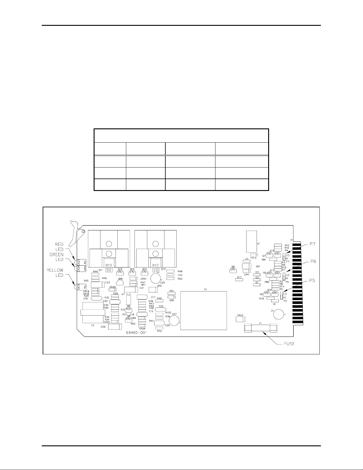
The Model 69460-001 Card contains three jumpers (P5, P6, P7). These jumpers set the logic levels of the
card's input control lines to either active HIGH (24 V) or active LOW (0.7 V). For operation in a
standard Central Page system using the Model 10961-001 Interface Panel or Model 10460-002 Interface
Panel, the jumpers must be set to active HIGH. Active HIGH is the factory default setting for all jumpers.
The active LOW setting is used only in special applications in which a custom-designed interface panel is
present or the card is being controlled by a device other than the interface panel. Refer to Figure 1.
Table 1. Jumper Settings
Jumper Function Active High Active Low
P5 Input #1 Short pins 2&3 Short pins 1 & 2
P6 Input #2 Short pins 2&3 Short pins 1 & 2
P7 Input #3 Short pins 2&3 Short pins 1 & 2
Figure 1. Model 69460-001 Crew’s Quarter’s Muting Card
\\s_eng\gtc proddoc s \st andard iom s - current release\42004 instr. manuals \ 42004-382a. doc
03/06
Page 3

Pub. 42004-382A
Model 69460-001 Crew’s Quarters Muting Card f or Centra-Page S y stem s Page: 3 of 5
Card Rack Installation
1. Open the Centra-Page system central cabinet to access the front panel.
2. Slide the Model 69460-001 Card into the card rack slot associated with the speaker to be muted.
Ensure that the connector at the rear of the card has plugged firmly into the connector in the card
rack.
3. Snap the white clip on the front of the card into place to secure the card in the card rack.
4. Open the Centra-Page cabinet to access the rear of the card rack. Attach the new terminal block label
as noted in Figu re 2.
5. Use No. 14, 16, or 18 AWG cable to complete the connections to the speakers. The distance between
th e centr al c abi net and the speak ers det erm ines the wire gau ge that is requ ire d: t he greater th e
distance to be covered, the larger the wire gauge that is needed. Refer to GAI-Tronics Pub. 42004135 for more information on speaker installation and wiring.
6. Refer to Figure 2 and Figure 3. The Model 10961-001 AMI Centra-Page Interface is equipped with a
Crew’s Quarters activation output (TBX04 position 9 - the black wire). Connect the black wire from
the 10961-001 TBX04 to the card rack terminal block position 2. Jumpers P1, P2 and P3 on the
69452-001 Interface PCBA are used to control which of the three tones will be broadcast to the
crew’s quarters. The jumper in position 1 and 2 make the tone non-active. The jumper in position 2
and 3 make the tone active. One or all the jumpers can be active. For example, to broadcast tones 1
and 2 only to the crew’s quarters, put P1 and P2 in position 2 and 3 and allow P3 to remain in
position 1 and 2.
Ω
Figure 2. Wiring at Card Rack
Figure 3. Model 69542-001 AMI Centra-Page
\\s_eng\gtc proddoc s \st andard iom s - current release\42004 instr. manuals \ 42004-382a. doc
03/06
Interfac e - jumper sect i o n
Page 4

Pub. 42004-382A
Model 69460-001 Crew’s Quarters Muting Card f or Centra-Page S y stem s Page: 4 of 5
Operation
Card Indicators
The card cont ai ns th ree in dicat or L EDs that are visib le f ro m the f ron t of th e card r ack. Th ese L EDs are
used to identify the card functions as follows.
Table 2 - Indicator Functions
LED Color/Position Function
Red (top) 24 V dc power is present on the card.
Green (middle) Audio is present on the speaker output.
Yellow (bottom)
One or more of the control inputs is active, which enables the
speaker output.
Speakers
8-Ohm O ut Operati on
When using the 8-ohm output connections, always use speakers of proper voice coil impedance and
power han d ing capability. Cons ult GA I - Tronics P ub. 42004-135 and 42004-220 for more details on
speaker installation and wiring.
70.7 Vol t Out Op eration
Greater speaker line distances from the central cabinet can be obtained by using the 70.7 V output
connection compared with using 8-ohm output. The individual speaker’s power level is determined by
the tap settings on the line-matching transformer. The use of these transformers allows the speakers to be
placed at longer distances from the central amplifier system without significant power loss.
The sum of the speaker power settings must not exceed the total power available from the amplifier
PCBA. For example, the 69460-001 PCBA’s 70.7 V output (~16 W out with ~27 V dc in) can drive
approximately eight speakers tapped at 2 watts each or four speakers tapped at 4 watts each.
\\s_eng\gtc proddoc s \st andard iom s - current release\42004 instr. manuals \ 42004-382a. doc
03/06
Page 5

Pub. 42004-382A
Model 69460-001 Crew’s Quarters Muting Card f or Centra-Page S y stem s Page: 5 of 5
Speaker Wiring Distance Guide
Cable distance should be kept as short as possible to reduce the power loss. The following chart
illustrates the correlation between three typical wire sizes and the distance that speakers with integral
dri vers or horns with sep ara te drivers c an be pl aced from the c e ntral card ra c k for a –1 dB loss (-20%
power loss). For a 0.5 dB loss, divide all lengths in half.
Table 2.
Speaker Wiring Guidelines for 69430-001 PCBA
Based on ~27 V DC Input to Card Rack Assembly
Speaker Output
Connection
18 AWG (0.82 mm2) 16 AWG (1.31 mm2) 14 AWG (2.08 mm2)
Wire Size
8-ohm out 77 feet (23.5 meters) 123 feet (37.5 meters) 196 feet (59.7 meters)
70.7 volt out 2,900 feet (884 meters) 4,700 feet (1,432 meters) 7,500 feet (2,286 meters)
Service Information
If the equipment requires service, contact your Regional Service Center for a return authorization number
(RA# ) . Equipmen t should b e shipped prepaid to GAI-T ronics with a ret urn a uthor ization number and a
purchase order number. If the equipment is under warranty, repairs will be made without charge. Please
include a written explanation of all defects to assist our technicians in their troubleshooting efforts.
Call 800-492-1212 for help identifying the Regional Service Center closest to you.
\\s_eng\gtc proddoc s \st andard iom s - current release\42004 instr. manuals \ 42004-382a. doc
03/06
Page 6

Warranty
Equipment. GAI-Tronics warrants for a period of one (1) year from the date of shipment, that any
GAI-Tronics equipment supplied hereunder shall be free of defects in material and workmanship, shall
comply with the then-current product specifications and product literature, and if applicable, shall be fit
for the purpose specified in the agreed-upon quotation or proposal document. If (a) Seller’s goods prove
to be defective in workmanship and/or material under normal and proper usage, or unfit for the purpose
specified and agreed upon, and (b) Buyer’s claim is made within the warranty period set forth above,
Buyer may return such goods to GAI-Tronics’ nearest depot repair facility, freight prepaid, at which time
they will be repaired or replaced, at Seller’s option, without charge to Buyer. Repair or replacement shall
be Buyer’s sole and exclusive remedy. The warranty period on any repaired or replacement equipment
shall be the greater of the ninety (90) day repair warranty or one (1) year from the date the original
equipment was shipped. In no event shall GAI-Tronics warranty obligations with respect to equipment
exceed 100% of the total cost of the equipment supplied hereunder. Buyer may also be entitled to the
manufacturer’s warranty on any third-party goods supplied by GAI-Tronics hereunder. The applicability
of any such third-party warranty will be determined by GAI-Tronics.
Services. Any services GAI-Tronics provides hereunder, whether directly or through subcontractors,
shall be performed in accordance with the standard of care with which such services are normally
provided in the industry. If the services fail to meet the applicable industry standard, GAI-Tronics will
re-perform such services at no cost to buyer to correct said deficiency to Company's satisfaction provided
any and all issues are identified prior to the demobilization of the Contractor’s personnel from the work
site. Re-performance of services shall be Buyer’s sole and exclusive remedy, and in no event shall GAITronics warranty obligations with respect to services exceed 100% of the total cost of the services
provided hereunder.
Warranty Periods. Every claim by Buyer alleging a defect in the goods and/or services provided
hereunder shall be deemed waived unless such claim is made in writing within the applicable warranty
periods as set forth above. Provided, however, that if the defect complained of is latent and not
discoverable within the above warranty periods, every claim arising on account of such latent defect shall
be deemed waived unless it is made in writing within a reasonable time after such latent defect is or
should have been discovered by Buyer.
Limitations / Exclusions. The warranties herein shall not apply to, and GAI-Tronics shall not be
responsible for, any damage to the goods or failure of the services supplied hereunder, to the extent
caused by Buyer’s neglect, failure to follow operational and maintenance procedures provided with the
equipment, or the use of technicians not specifically authorized by GAI-Tronics to maintain or service the
equipment. THE WARRANTIES AND REMEDIES CONTAINED HEREIN ARE IN LIEU OF AND
EXCLUDE ALL OTHER WARRANTIES AND REMEDIES, WHETHER EXPRESS OR IMPLIED BY
OPERATION OF LAW OR OTHERWISE, INCLUDING ANY WARRANTIES OF
MERCHANTABILITY OR FITNESS FOR A PARTICULAR PURPOSE.
Return Policy
If the equipment requires service, contact your Regional Service Center for a return authorization number
(RA#). Equipment should be shipped prepaid to GAI-Tronics with a return authorization number and a
purchase order number. If the equipment is under warranty, repairs or a replacement will be made in
accordance with the warranty policy set forth above. Please include a written explanation of all defects to
assist our technicians in their troubleshooting efforts.
Call 800-492-1212 (inside the USA) or 610-777-1374 (outside the USA) for help identifying the
Regional Service Center closest to you.
(Rev. 10/06)
 Loading...