

Page 1
Pub. 42004-681L2A
GAI-TRONICS® CORPORATION
A HUBBELL COMPANY
Model 69320-001
Voice Network Ada pter
Confidentiality Notice
This manua l is provide d sole ly as an operatio nal, installation, and ma inte nance guide and conta ins se nsitive
business and technical information that is confidential and proprietary to GAI-Tronics. GAI-Tronics retains
all intellectual property and other rights in or to the information contained herein, and such information may
only be us ed in connection with t he op erat ion of your GAI-T ronics pr oduct or system. This ma nual ma y
not b e discl osed i n any f orm, in whol e or in part, directly or indirectly, to any third party.
General Information
The Model 69320-001 Voice Network Adapter (VNA) allows voice communication between
interconnected SmartSeries systems. It is installed in a 10457 Series Card Rack (Card Rack) and is
controlled by a 69254 Series or 69440 Series Master Control Unit (MCU) installed in that same card rack.
The VNA is designed exclusively for use in a SmartSeries system, and is not intended for use with other
types of equipment.
Description of Major Compo nents
Front Pa nel LEDs
The following table describes the LEDs mounted on the VNA’s front panel:
LED Status Description
ON LINE On The MCU is running and is configured to recognize the VNA.
Off
VNA FLT On
Off The “On” condition is not occurring.
MCU FLT On
Off The “On” condition is not occurring.
The VNA is not receiving power from the card rack or the MCU is not
properly configured to recognize the VNA.
The MCU has l o st communic ation w i th t he VNA. T he MCU and the VNA
continuously update hands haki ng inf ormation. I f the VNA is not updat ing that
information as the MCU expects, then the MCU turns on this LED.
The VNA has lost communi c ation w i th the MCU. The M CU and the VNA
continuously update handshaking information. If the MCU is not updating that
information as the VNA expects, then the VNA turns on this LED. This LED
may be On durin g maintenanc e of the MCU.
GAI-Tronics Corporation P.O. Box 1060, Readi ng, PA 19607-1060 USA
610-777-1374 800-492-1212 Fax: 610-796-5954
ISIT WWW.GAI-TRONICS.COM FOR PRODUCT LITERATURE AND MANUALS
V
Page 2

Pub. 42004-681L2A
Model 69320-001 Voice Network Adapter Page: 2 of 14
LED Status Description
RAI/RYEL On
The VNA is receiving the T1 Yellow Alarm (Remote Alarm Indication), and is
not transmitting the T1 Yellow Alarm.
Flashing
90% On
Flashing
50% On
Flashing
10% On
The VNA both is receiving and is transmitting the T1 Yellow Alarm. The
frequency of flashing is approximately one Hertz.
The VNA is transmitting the T1 Yellow Alarm, and is not receiving the T1
Yellow Alarm. The freque ncy of fla shing is a pprox imately o ne Hertz.
The T1 transceiver on the VNA is not initialized. The frequency of flashing is
approxi mate ly one Hert z .
Off All of the above four conditions are not occurring.
AIS/RBL On
The VNA is receiving the T1 Blue Alarm (Alarm Indication Signal), and is not
transmitting the T1 Blue Alarm.
Flashing
90% On
Flashing
50% On
Flashing
10% On
The VNA both is recei ving and is transmitting the T1 Blue Alarm. The
frequency of flashing is approximately one Hertz.
The VNA is transmitting the T1 Blue Alarm, and is not receiving the T1 Blue
Alarm. The frequenc y of flashing is approxi ma tely one Hertz .
The T1 transceiver on the VNA is not initialized. The frequency of flashing is
approxi mate ly one Hert z .
Off All of the above four conditions are not occurring.
LOF/RLOS On
The VNA is n o t synchronized with t he receiv ed T1 si gnal (Loss of Fr ame or
Rece ive L oss of S ynchroniz ation), and d oes not detec t a s hort on its T 1
transmit line.
Flashing
90% On
The VNA both is not synchronized with the received T1 signal and detects a
short on its T1 t r ansmit line. The freque ncy of f l ashing is approxi matel y one
Hertz.
Flashing
50% On
Flashing
10% On
The VNA detects a s hort on it s T1 trans mit lin e, and is synchronize d with the
rece ived T1 si gnal. The fre quency of f l ashing is approxima tely one H ertz.
The T1 transceiver on the VNA is not initialized. The frequency of flashing is
approxi mate ly one Hert z .
Off All of the above four conditions are not occurring.
LOS/RCL On
The VNA is n ot rec e ivi n g a T1 signal ( Loss of Signal or Receive Carr ier
Loss), and does not detect an open on its T1 transmit line.
Flashing
90% On
Flashing
50% On
Flashing
10% On
The VNA both is not receiving a T1 signal and detects an open on its T1
transmit line. The freque ncy of flashing is approx imat e ly one Hertz .
The VNA detects an open on its T1 transmit line, and is receiving a T1 signal.
The frequency of flashing is approximately one Hertz.
The T1 transceiver on the VNA is not initialized. The frequency of flashing is
approxi mate ly one Hert z .
Off
\\s_eng\gtc proddoc s \st andard iom s - current release\42004 instr. manuals \ 42004-681l2a. doc
06/04
All of the above four conditions are not occurring.
Page 3
Pub. 42004-681L2A
Model 69320-001 Voice Network Adapter Page: 3 of 14
Connections to the Fi eld Wiring Te rminal Bl ocks
69320-001 Voice Ne twork Adapter Connect ions to the Field Wiring
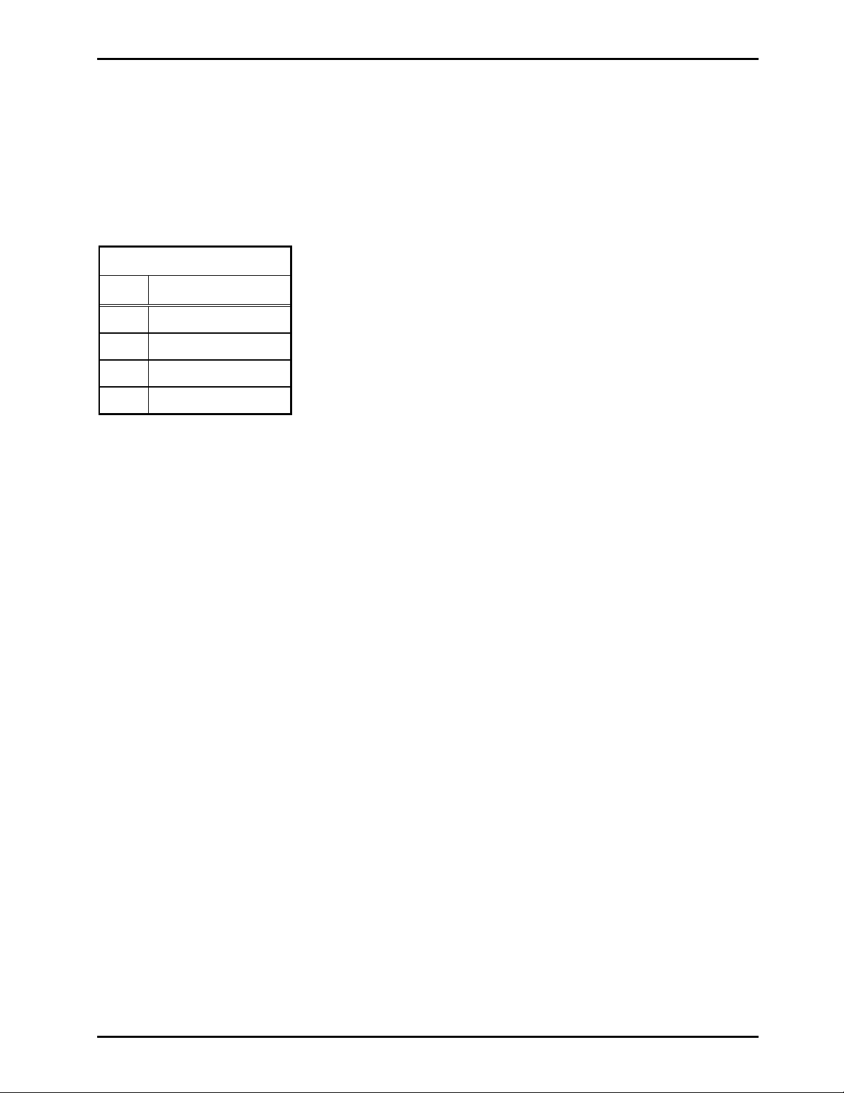
Connections to the field are made via the upper DB25 connector on the rear of the 10457 Series Card Rack
assembly. This connector may be utilized by a direct connection of a DB25 cable to the field equipment, a
DB25 cable to a DIN rail-mounted terminal block adapter, or with the use of a DB25-to-RJ45 connector
adapter. The pinout definition for the DB25 connection is shown is the table below.
Upper DB25 Connector
Pin Signal
1 Tx (ring)
2 Tx (tip)
5 Rx (ring)
6 Rx (tip)
Included with the VNA are two DB25-to-RJ45 connector adapters. The 21246-014 Connector Adapter
brings the transmit pair to the RJ45 pins 1 & 2 and the receive pair to pins 4 & 5. The 21246-008
Connector Adapter brings the transmit pair to the RJ45 pins 4 & 5 and the receive pair to pins 1 & 2. These
adapters permit the use of non-crossover Ethernet cables for the connections to field equipment utilizing
these same pins on an RJ45 connector.
Cabling to the field equipment should be a twisted pair design.
\\s_eng\gtc proddoc s \st andard iom s - current release\42004 instr. manuals \ 42004-681l2a. doc
06/04
Page 4
Pub. 42004-681L2A
Model 69320-001 Voice Network Adapter Page: 4 of 14
Switch and J umper Settings
Overview
Several switch and jumper settings are required for proper operation of the VNA Card. The following
settings are set during the system commissioning and programming and should not be changed. If replacing
an existing 69266-001 T1 card or VNA card for maintenance purposes, then be sure to replicate the switch
and jumper setting of the card being replaced. Refer to Figure 1 for the switch and jumper locations.
Front Panel DIP Swi tch (SW2) Sett ings
NOTE: The front panel D IP switches (SW2 ) may b e u pdat e d with out poweri ng down th e card r ack and
without resetting the MCU.
Position Number Name
Top 1 Line Build 0 (LB0)
2 Line Build 1 (LB1)
3 Line Build 2 (LB2)
4 Receive Equalizer G ain Limit
5 Lamp Test
6 Customer Disconnect Enable
7 Local Loop Back
Bottom 8 Remote Loop Back
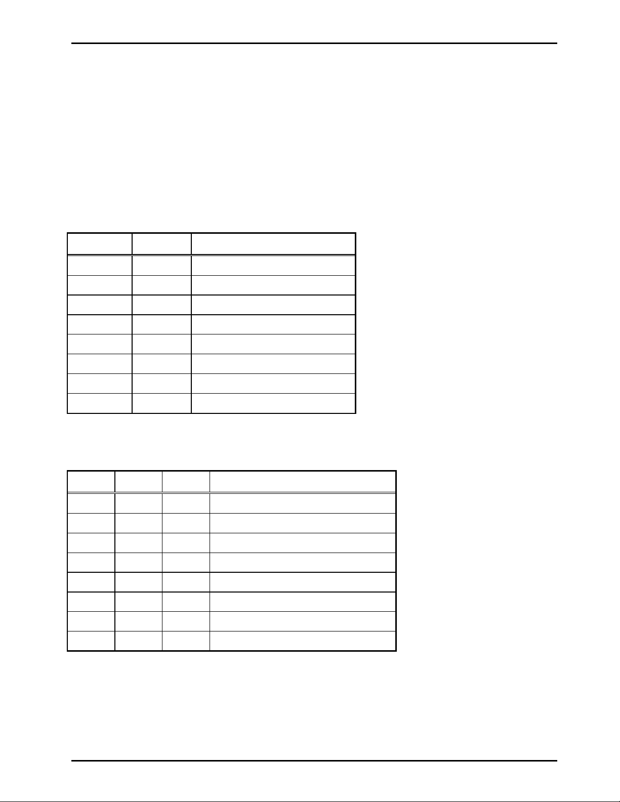
The Line Build # switches control the “line build” (signal’s amplitude) of the T1 transmit line. Set the Line
Build # switches according to the following table:
LB0 LB1 LB2 T1 Line Length
Open Open Open DSX-1 (0 to 133 feet) / 0 dB CSU
Open Open Closed DSX-1 (133 to 266 feet)
Open Closed Open DSX-1 (266 to 399 feet)
Open Closed Closed DSX-1 (399 to 533 feet)
Closed Open Open DSX-1 (533 to 655 feet)
Closed Open Closed -7.5 dB CSU
Closed Clos ed Open -15 dB CSU
Closed Closed Closed -22.5 dB CSU
\\s_eng\gtc proddoc s \st andard iom s - current release\42004 instr. manuals \ 42004-681l2a. doc
06/04
Page 5

Pub. 42004-681L2A
Model 69320-001 Voice Network Adapter Page: 5 of 14
The R eceiv e Equalizer Gain Limit s witch c ontrols the similarly named featu re of t he T1 transc e iver. Set
the Receive Equalizer Gain Limit switch according to the following table:
Open
Closed
-36 dB (long haul)
-15 dB (limited long haul)
The Lamp Test s witch t u rns on all LEDs on t he VNA ’s front p anel. I t is used during produc tion of th e
VNA. The Lamp Test switch will not function when the VNA det ects th e MCU (MCU FLT LED is Off).
Set the Lamp Test switch according to the following table:
Open
Close
All front panel LEDs function normally.
All front panel LEDs are ON
The Customer Disconnect function presents a well-behaved signal on the T1 line. This signal is sometimes
useful during troubleshooting and verification. Set the Customer Disconnect Enable switch according to the
following table:
Open
Closed
The T1 transceiver is operating normally.
The Customer Disconnect signal is being transmitted on the T1 line. This setting disrupts the
T1 signal and the MCU reports a T1 line fault.
The Loc al Loop Back featu re sometimes is used during troubleshoot ing. Set the L oc al Lo op Back s w itch
according to the following table:
Open
Closed
The T1 transceiver is operating normally.
The “Framer Loopback” feature of the T1 transceiver is enabled. The T1 transceiver transmits
the Blue Alarm on the T1 transmit line during this condition. This setting disrupts the T1 signal
and the MCU reports a T1 line fault. This setting causes the VNA to receive the T1 signal it
normally would transmit, while actually transmitting the Blue Alarm.
The Remote Loop Back feature sometimes is used during troubleshooting. Set the Remote Loop Back
switch according to the following table:
Open
Closed
The T1 transceiver is operating normally.
The “Remote Loopback” feature of the T1 transceiver is enabled. This setting disrupts the T1
signal and the MCU reports a T1 line fault. This setting causes the VNA to transmit its received
T1 s ignal. The T1 standards me ntion two types of lo opbacks: “line ” and “pa yload”; this
loopback is a “line” loopback.
\\s_eng\gtc proddoc s \st andard iom s - current release\42004 instr. manuals \ 42004-681l2a. doc
06/04
Page 6

Pub. 42004-681L2A
Model 69320-001 Voice Network Adapter Page: 6 of 14
Internal DIP Switch (SW1) Settings
NOTE: Internal DIP switch (SW1) changes only take effect after powering down the Card Rack; resetting
the MCU is insufficient.
Position Number Name
Left 1 ST-Bus Clock Master
2 T 1 Clock Master
3 T1 Synchronous
4 E1 Select
5 Sampling Rate Select
6 Reserved
7 Reserved
Right 8 Reserved
Set the ST-Bus Clock Master switch according to the following table:
Open
The VNA generates the Card Rack’s backplane ST-Bus clock signals. The VNA is the STBus Clock Master.
Closed
The VNA receives the Card Rack’s backplane ST-Bus clock signals. The VNA is a ST-Bus
Clock Slave.
Set the T1 Clock Master switch according to the following table:
Open
The VNA uses its received T1 signal’s timing to generate its transmitted T1 signal’s timing.
The VNA is a T1 Clock Sl ave.
Closed
The VNA uses the Card Rack’s backplane ST-Bus clock signals to generate its transmitted T1
signal’s timing. The VNA is the T1 Clock Master.
Set t he T1 S ynchronous switch accord ing to the follow ing table:
Open
The VNA is frequency locked to the received T1 signal. This setting is ignored if the VNA is
both a ST - B us Clock Slave a nd a T 1 Clock Slav e.
Closed
The VNA is not frequency locked to the received T1 signal. “Elastic store” buffers in the T1
transceiver integrated circuit either duplicate or drop a frame as needed.
Set the E1 Select switch according to the following table:
Open
Closed
The VNA uses T1 signaling.
The VNA uses E1 signaling. Note: upon initial release of the VNA, this feature does not
function properly.
\\s_eng\gtc proddoc s \st andard iom s - current release\42004 instr. manuals \ 42004-681l2a. doc
06/04
Page 7

Pub. 42004-681L2A
Model 69320-001 Voice Network Adapter Page: 7 of 14
The Sample Rate Select switch configures the VNA’s codec’s sampling rate. The VNA’s codec can run at
either 8,000 samples per second (8 kHz), or 16,000 samples per second (16 kHz). The VNA accepts and
generates 69266-001 T1 Interface wide bandwidth page audio regardless of the setting of this switch. The
FAQ section has more information on wide bandwidth paging compatibility with the 69266-001 T1
Interface. Set the Sampling Rate Select switch according to the following table:
Open
The VNA’s codec uses 8 kHz sampling. Always use this setting if wide bandwidth paging is
disabled. This setting is recommended.
Closed
The VNA’s codec uses 16 kHz sampling.
Set the Reserved switches according to the following table:
Open
Closed
Use this setting to help insure future compatibility.
Do not use this setting. Using this setting may increase the risk unexpected behavior when
upgrading the VNA.
Rotary S witch and Jum per Setting s
The 2xx/3xx Address (P2) shorting clip selects part of the base input/output address used by the MCU when
accessing the VNA.
The Board Address (S2) rotary switch selects part of the base input/output port address used by the MCU
when accessing the VNA.
The Board Identification (S1) rotary switch lets the MCU distinguish between multiple VNAs installed in
the same card rack.
\\s_eng\gtc proddoc s \st andard iom s - current release\42004 instr. manuals \ 42004-681l2a. doc
06/04
Page 8

Pub. 42004-681L2A
Model 69320-001 Voice Network Adapter Page: 8 of 14
Figure 1. Model 69320-001 Voice Network Adapter Board Layout Diagram
\\s_eng\gtc proddoc s \st andard iom s - current release\42004 instr. manuals \ 42004-681l2a. doc
06/04
Page 9

Pub. 42004-681L2A
Model 69320-001 Voice Network Adapter Page: 9 of 14
Changing t o a 69320-0 01 VNA from a 69266-001 T1 Inte rface
NOTE: We recommend upgrading all older Access Panel Interfaces (APIs) (Models 69257-001, 69257002, and 69257-003) to the most recent version (69257-004 or later) when upgrading a 69266-001 T1
Interface to a 69320-001 VNA. See the FAQ section for more information.
The 69266-001 T1 Interface uses a different switch and jumper collection than the VNA. The following
text states how to convert the T1 Interface switch and jumper setting to the VNA switch and jumper
settings.
The 2xx/3xx Address (P2) shorting clip should be set to the 2xx position if the shorting clip on J1 of the T1
Interface is closer to the back of the T1 Interface. Otherwise, set to the 3xx position when the shorting clip
on J1 of the T1 i n terface is closer to t he front of the T1 Interface.
OTE: The silkscreen for J1 on the T1 interface should be blacked out; if not blacked out, then that
N
silkscreen shows the 2xx / 3xx position reversed from the actual meaning of J1.
The Board Address (S2) rotary switch on the VNA should match the Board Address rotary switch on the T1
Interface.
The Board Identification (S1) rotary switch on the VNA should match the Board Identification rotary
switch on the T1 Interface.
Internal DIP switch #1 (SW1) (ST-Bus Clock Master) should be set to CLOSED if J3 of the T1 Interface is
set to ING (ignore – shorting clip towards front). Otherwise, set to OPEN when J3 of the T1 Interface is set
to GEN (generate – shorting clip towards back).
Internal DIP switch #2 (S W1) (T1 Clock Mast er) s hould b e set to CLOSED if J4 of the T1 Interfa ce is set to
GEN (generate – shorting clip towards front). Otherwise, set to OPEN when J4 of the T1 Interface is set to
REC (receive – shorting clip towards back).
Internal DIP switch #3 (S W1) (T1 Synchro nous) s h ould b e set to OPEN.
Internal DIP switch #4 (S W1 ) (E1 Select) shou ld be set to OPEN.
Internal DIP switch #5 (SW1) (Sampling Rate Select) should be set to OPEN.
Internal DIP switch #6 (SW1) through #8 (Reserved) should be set to OPEN.
\\s_eng\gtc proddoc s \st andard iom s - current release\42004 instr. manuals \ 42004-681l2a. doc
06/04
Page 10

Pub. 42004-681L2A
Model 69320-001 Voice Network Adapter Page: 10 of 14
For Front Panel D I P switch #1 ( SW2) ( Line Bu ild 0), Fr ont Pa ne l D IP sw itch #2 (Lin e Buil d 1), and Front
Panel DIP switch #3 (Line Build 2) select the closest matching distance from the following two tables. If
the S3 T1 Interface switch settings are not listed in the table, then select all OPEN for the VNA Line Build
switches.
S3 (XMIT EQUALIZATION) on T1 Interface
0' 75' 150' 225' 300' 375' 450' 525' 600' 675' 750' 825'+
S3-1
S3-2
S3-3
S3-4
S3-5
S3-6
S3-7
S3-8
- - -
- - - - - -
- - -
- - - - - -
X
-
- -
- -
X
- -
X
- - - - - - - - -
“X” means closed; “-” means open.
Build 0 Build 1 Build 2 Distance
Open Open Open DSX-1 (0 to 133 feet) / 0 dB CSU
Open Open Closed DSX-1 (133 to 266 feet)
Open Closed Open DSX-1 (266 to 399 feet)
X X X
X X X
X
- -
- -
X
- -
X
Line Build on VNA
- - -
X X X
X X X X X X
- - -
X X X
X X X X X X
X
- -
X
- -
X
-
- X
X -
-
- -
-
-
X
- -
Open Closed Closed DSX-1 (399 to 533 feet)
Closed Open Open DSX-1 (533 to 655 feet)
Closed Open Closed -7.5 dB CSU
Closed Closed Open -15 dB CSU
Closed C losed Close d -22.5 dB CSU
Fr ont Pa ne l D I P switch #4 ( SW2) ( Receive Equaliz er Gain L imit) should be s et to OP EN.
Front Panel DIP switch #5 (SW2) (Lamp Test) should be set to OPEN.
Front Panel DIP switch #6 (SW2) (Customer Disconnect Enable) should be set to OPEN.
Fr ont Pa ne l DIP s witch #7 (SW 2) (Local Lo op Back) should be set to OPE N.
Fr ont Pa nel DIP switc h #8 (S W 2) (Re m ote Loop Back) s hould b e set t o O PEN.
\\s_eng\gtc proddoc s \st andard iom s - current release\42004 instr. manuals \ 42004-681l2a. doc
06/04
Page 11

Pub. 42004-681L2A
Model 69320-001 Voice Network Adapter Page: 11 of 14
Operation
After installation, the Model 69320-001 Voice Network Adapter (VNA) should start automatically. The
VNA requires no dir ect user inter venti on dur ing normal operat ions.
Installation and Maintenance
Direct questions about installation of this product to the GAI-Tronics Field Service Department at 800-4921212 inside the USA or 610-777-1374 outside the USA.
Installa tion Guidelines
WARNING
Disconnect po wer t o the card rack before performing any mai ntenance.
Installa tion Instructions
1. Remove the VNA from its protective carton.
2. Verify that power is disconnected to the card rack prior to installation.
3. Verify that the switch and jumper settings described in the Switch and Jumper Settings section on page
4 are set in accordance with the instructions in your system manual.
4. Align the VNA into the upper and lower tracks for the card rack slot.
5. Slide the VNA toward the rear of the card rack until it comes in contact with the connector on the
backplane.
6. Firmly press on the front bezel until the VNA is seated in the backplane connector, and tighten the two
screws located on the front bezel to secure it to the card rack.
Remo ving the VN A Card from the Card Rack
1. Remove power from the card rack.
2. Remove the two screws on the front bezel that secures the VNA to the card rack.
3. Gently diseng age the VNA fr om the conn ecto r o n the backp l ane and slide the VN A out of the car d
rack.
\\s_eng\gtc proddoc s \st andard iom s - current release\42004 instr. manuals \ 42004-681l2a. doc
06/04
Page 12

Pub. 42004-681L2A
Model 69320-001 Voice Network Adapter Page: 12 of 14
F requently Asked Questions
Q: Is the 69320-001 VNA compatible with the public switched telephone network?
A: No.
Q: When does the 69320-001 VNA generate at T1 Yellow Alarm?
A: When either (1) it does not det ect a signal on its T 1 receiv e lin e, or (2 ) wh en it detects the MCU and is
not synchronized with the signal on its T1 receive line and is not receiving a T1 Blue Alarm.
N
OTE: When receiving a T1 Blue Alarm the VNA is not synchronized with its T1 receive line, by the very
nat ure of t he T1 Bl ue Alarm.
Q: When does the 69320-001 VNA generate a T1 Blue Alarm?
A: When either (1) it does detect a signal on its T1 receive line and does not detect the MCU, or (2) one of
its loopback functions are enabled.
Q: What is the T1 Red Alarm?
A: The T 1 Red Alarm is the Loss of S i gnal (L OS) or Rec e ive Carrier Loss (R CL) condition.
Q: Why do th e LEDs have two labels?
A: One label is the newer vernacular; the other is the older vernacular.
Q: Why does the f ront panel “La mp Test ” switch not f unct ion while t he VNA detec ts t he MCU is runn ing
(the MCU FLT LED is off)?
A: That behavior is by design. That design choice helps prevent the diagnostic function of the front panel
LEDs from being defeated while the system is in use.
Q: What feature does setting all DIP switches to closed, both rotary switches to zero, and the 2xx/3xx
jumper to 3xx enable?
A: Doing so enables all four relays on the VNA, lights all LEDs on the VNA, and routes a 2.0000 kHz tone
(assuming a different signal has not been loaded after power up) to all backplane audio lines and backplane
ST-Bus data lines. This feature is used to approximate the maximum power consumption and
electromagnetic emissions of the VNA. This feature interferes with normal system operations, and is
disabled while the VNA detects the MCU is running.
Q: Is the 69320-001 VNA capable of generating E1 timing instead of T1 timing.
A: No.
Q: Immediately after power up, all four T1 status LEDs are flashing 10% on, indicating the T1 transceiver
on the VNA is not initialized. Is there anything that can be done to correct this situation?
A: Yes.
Step 1: Remove power from the card rack.
Step 2 : Disc onnect the T1 lin e fr om the VN A.
Step 3: Apply power to the card rack.
Step 4: Reconnect the T1 line to the VNA.
It is not necessary to wait for the MCU to finish booting before reconnecting the T1 line to the VNA. Steps
1 and 2 may be swapped; however, it is important that the T1 line be connected to the VNA after the card
rack is powered for this fix to be effective. Resetting the MCU should have no effect on the situation.
\\s_eng\gtc proddoc s \st andard iom s - current release\42004 instr. manuals \ 42004-681l2a. doc
06/04
Page 13

Pub. 42004-681L2A
Model 69320-001 Voice Network Adapter Page: 13 of 14
Specification s
Electrical
Board
Power................................................................................................. 950 mA maximum @ +5 V dc ±5%
125 mA maximum @ +12 V dc ±10%
125 mA maximum @ -12 V dc ±10%
T1 Parameters
NOTE: the 69320-001 VNA is not compatible with the public switched telephone network.
Encoding ..................................................................................... (Bipolar with 8 Zero Substitution) B8ZS
Framing..........................................................................................................(Extended Superframe) ESF
T1 Cablin g
Cable characteristic impedance......................................................................................100 ohms nominal
Maximum cable length...............................................................................................................6,000 feet
Digital Audio - Party Line or Narrow Bandwidth Paging
Encoding .................................................................................µ-Law per CCITT Recommendation G.711
Sampling rate.................................................................................................................... 8 kHz ±32 ppm
Digital Audi o - Wide Band width Paging
Encoding .................................................... ADPCM 32 kbps, µ-Law per CCITT Recommendation G.726
Sampling rate encoding...................................................................8 kHz up sampled to 16 kHz ±32 ppm
Sampling rate decoding.............................................................. 16 kHz down sampled to 8 kHz ±32 ppm
Card Rack Page Au dio from one VNA to another VNA in a diffe rent Card Rack – Narrow Band width
Frequency response..........................................................................................250 Hz to 3.5 kHz ±0.5 dB
Distortion..........................................................THD <2.0% @ 1,020 Hz sine wave, -10 dB ref. 1.5 Vrms
Card Rack Page Au dio from one VNA to another VNA in a diffe rent Card Rack – Wide Bandwid th
Frequency response..........................................................................................250 Hz to 3.5 kHz ±0.5 dB
Distortion..........................................................THD <2.0% @ 1,020 Hz sine wave, -10 dB ref. 1.5 Vrms
Card Rack Party A udio from one VNA to another VNA i n a different Card Rack
Frequency response..........................................................................................250 Hz to 3.5 kHz ±0.5 dB
Distortion..........................................................THD <2.0% @ 1,020 Hz sine wave, -10 dB ref. 1.5 Vrms
\\s_eng\gtc proddoc s \st andard iom s - current release\42004 instr. manuals \ 42004-681l2a. doc
06/04
Page 14

Pub. 42004-681L2A
Model 69320-001 Voice Network Adapter Page: 14 of 14
Envi ronmental
Temperature range (operating/storage)..............................................+32° F to +122° F (0° C to +50° C)
Relative humidity:.............................................................................................10–85% non-condensing
Mechanical
Unit dimensions ............................................ 10.3 H × 0.780 W × 9.07 D inches (262 × 19.9 × 231 mm)
Unit weight ...................................................................................................0.86 lbs. nominal (0.39 kg)
Replaceme nt Parts
The 69320-001 VNA has no field replaceable components.
\\s_eng\gtc proddoc s \st andard iom s - current release\42004 instr. manuals \ 42004-681l2a. doc
06/04
Page 15

Warranty
Equipment. GAI-Tronics warrants for a period of one (1) year from the date of shipment, that any
GAI-Tronics equipment supplied hereunder shall be free of defects in material and workmanship, shall
comply with the then-current product specifications and product literature, and if applicable, shall be fit
for the purpose specified in the agreed-upon quotation or proposal document. If (a) Seller’s goods prove
to be defective in workmanship and/or material under normal and proper usage, or unfit for the purpose
specified and agreed upon, and (b) Buyer’s claim is made within the warranty period set forth above,
Buyer may return such goods to GAI-Tronics’ nearest depot repair facility, freight prepaid, at which time
they will be repaired or replaced, at Seller’s option, without charge to Buyer. Repair or replacement shall
be Buyer’s sole and exclusive remedy. The warranty period on any repaired or replacement equipment
shall be the greater of the ninety (90) day repair warranty or one (1) year from the date the original
equipment was shipped. In no event shall GAI-Tronics warranty obligations with respect to equipment
exceed 100% of the total cost of the equipment supplied hereunder. Buyer may also be entitled to the
manufacturer’s warranty on any third-party goods supplied by GAI-Tronics hereunder. The applicability
of any such third-party warranty will be determined by GAI-Tronics.
Services. Any services GAI-Tronics provides hereunder, whether directly or through subcontractors,
shall be performed in accordance with the standard of care with which such services are normally
provided in the industry. If the services fail to meet the applicable industry standard, GAI-Tronics will
re-perform such services at no cost to buyer to correct said deficiency to Company's satisfaction provided
any and all issues are identified prior to the demobilization of the Contractor’s personnel from the work
site. Re-performance of services shall be Buyer’s sole and exclusive remedy, and in no event shall GAITronics warranty obligations with respect to services exceed 100% of the total cost of the services
provided hereunder.
Warranty Periods. Every claim by Buyer alleging a defect in the goods and/or services provided
hereunder shall be deemed waived unless such claim is made in writing within the applicable warranty
periods as set forth above. Provided, however, that if the defect complained of is latent and not
discoverable within the above warranty periods, every claim arising on account of such latent defect shall
be deemed waived unless it is made in writing within a reasonable time after such latent defect is or
should have been discovered by Buyer.
Limitations / Exclusions. The warranties herein shall not apply to, and GAI-Tronics shall not be
responsible for, any damage to the goods or failure of the services supplied hereunder, to the extent
caused by Buyer’s neglect, failure to follow operational and maintenance procedures provided with the
equipment, or the use of technicians not specifically authorized by GAI-Tronics to maintain or service the
equipment. THE WARRANTIES AND REMEDIES CONTAINED HEREIN ARE IN LIEU OF AND
EXCLUDE ALL OTHER WARRANTIES AND REMEDIES, WHETHER EXPRESS OR IMPLIED BY
OPERATION OF LAW OR OTHERWISE, INCLUDING ANY WARRANTIES OF
MERCHANTABILITY OR FITNESS FOR A PARTICULAR PURPOSE.
Return Policy
If the equipment requires service, contact your Regional Service Center for a return authorization number
(RA#). Equipment should be shipped prepaid to GAI-Tronics with a return authorization number and a
purchase order number. If the equipment is under warranty, repairs or a replacement will be made in
accordance with the warranty policy set forth above. Please include a written explanation of all defects to
assist our technicians in their troubleshooting efforts.
Call 800-492-1212 (inside the USA) or 610-777-1374 (outside the USA) for help identifying the
Regional Service Center closest to you.
(Rev. 10/06)
 Loading...