

Page 1

Pub. 42004-221A
GAI-TRONICS® CORPORATION
A HUBBELL COMPANY
Model 69037-101
Station Card for Centra-Pa ge Sy stems
Confidentiality Notice
This manua l is provide d sole ly as an operatio nal, installation, and ma inte nance guide and conta ins
sensitive business and t e chnical informatio n tha t is confidentia l and pr opri et ary to GAI- Tronics. GAITronics retains all intellectual property and other rights in or to the information contained herein, and
such information may on ly be u sed in conn e ction with the operatio n of you r GAI-Tr onics p rodu c t or
system. This manu al may not be dis clos e d in any form, in whole or in pa rt, direct ly or i ndir ectly, to a ny
third pa r ty.
Introduction
GAI-Tronics Centra-Page system provides dependable paging and party line communications for rugged
and haza rdous industrial fac ilit ies. Centr a-P age fea tur e s central ly-lo c ated electronics that provi de
environmental protection and unitized amplification for easy maintenance. Standard Model 10468-002
Centra-Page cabinets can support up to 30 handset stations and in most cases up to 60 paging speakers.
Alarms and telephone interfacing can also be added to Centra-Page systems.
The heart of the syst em is a centrally- located card r ack containing pri nted circuit board assembli es
(PCBAs) Model 69037-101. One plug-in PCBA, also referred to as a line card, is placed in the central
card rac k ass e mb ly for each independ e nt statio n and sp eaker. Ea c h line ca rd contai ns a handset dc po w er
source, dual-switching relays and a 16-watt speaker amplifier with 8-ohm and 70.7 V line outputs.
Additionally, each card has a paging-level speaker volume control (which does not
level), and a removable link to silence the speaker amplifier for page calls from that station, preventing
acoustic feedback. Each card also contains five LED indicators for operating condition or mode.
The Model 69037-101 Station Line Card plugs into a Model 10461-002 Centra-Page Card Rack located
in the central cabinet. The central cabinet is installed in a non-hazardous area. The Model 69037-101
contains both the handset amplifier power supply and an amplifier for an associated speaker or
horn/driver combination.
As shown in Figure 2, the LEDs located along the edge of the card allow a technician to easily perform
tr oubleshooting at th e central cabin et. Ea c h line ca rd conta ins a 16-wat t audio amplifier fed f rom the
page line bus that is intended to drive loudspeakers in the vicinity of the handset station. There is a
volume control and mute link on the input to each amplifier. The control and link are actually located on
the 10461-002 Card Rack so adjustments for various locations are maintained even though line cards are
replaced or exchanged.
affect alar m sig nal
GAI-Tronics Corporation P.O. Box 1060, Readi ng, PA 19607-1060 USA
610-777-1374 800-492-1212 Fax: 610-796-5954
ISIT WWW.GAI-TRONICS.COM FOR PRODUCT LITERATURE AND MANUALS
V
Page 2
Pub. 42004-221A
Model 69037-101 St ation Card for Centra-Page Sy stem s Page: 2 of 4
The function of the mutin g is to silence th e l oudspeak ers in the vi cinity of a handset stat ion when p age
calls are initia ted fr om that sta tion. This prevents acoustic feedback w hich ma y be a proble m depe nding
on loudspeaker location. The equipment is not configured for this option when shipped from the factory.
If the muting feature is desired, please refer to the 10461-002 Card Rack manual for instructions on how
to enable this option.
Installation
1. Open the Centra-Page cabinet to access the front panel.
2. Slide the 69037-101 card into the grooves associated with the
proper station. Make sure that the conn ector at t he rear of th e
card has plugged firmly into the connector in the card rack. All
the components should face to the right. The card is keyed so
that it cannot be plugged in backwards.
3. Snap the white clip on the front of the ca rd in to pla ce t o sec ure
the card in the card rack.
4. Open the Centra-Page cabinet to access the rear of the card
rack.
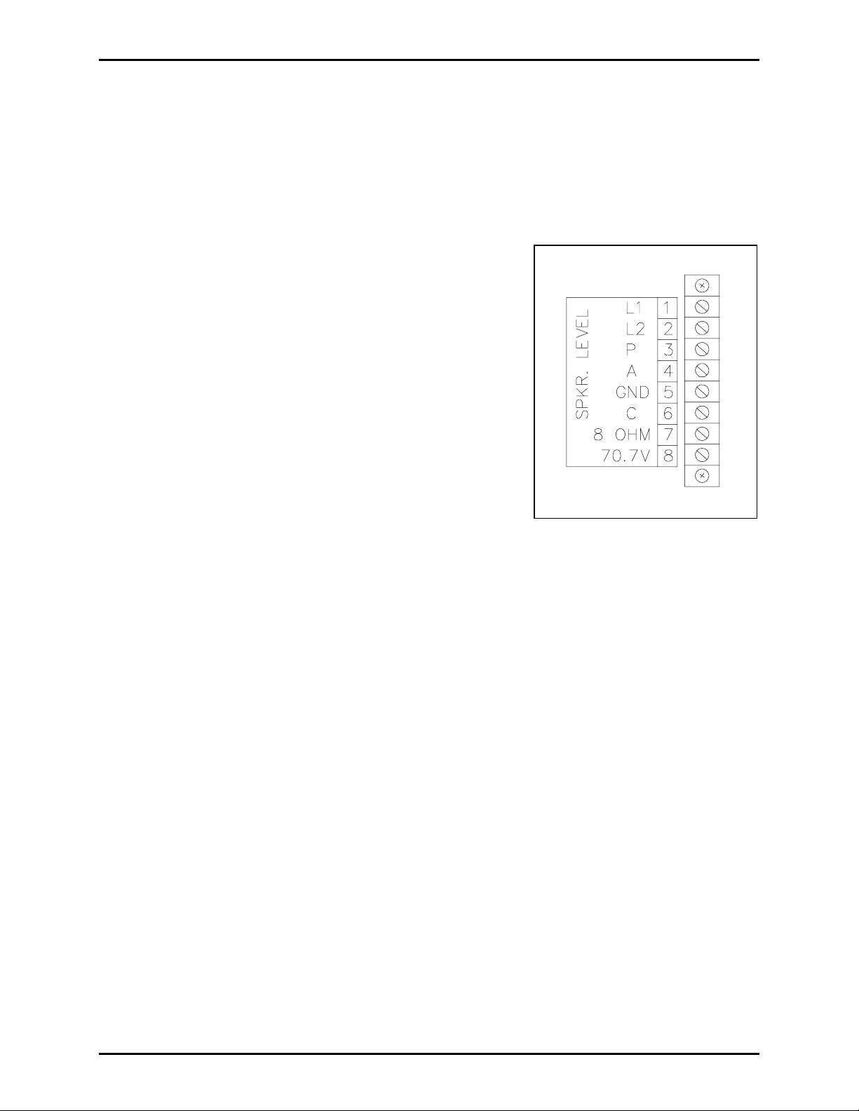
5. Refer to Figure 1. Complete the connections to the terminal
blocks a s noted.
6. Make the connections to the speakers using 14, 16, or 18AWG
Figure 1. Wiring to Card Rack
cable. The gauge of wire needed is determined by the distance
betwe en the cent ral cabinet and the sp eakers . Th e l arger the wire gauge, the greater the dista nce t h at
can be covered
7. Adjust the speaker level using a small standard screwdriver inserted into the hole labeled SPKR.
LEVEL.
\\s_eng\gtc proddoc s \st andard iom s - current release\42004 instr. manuals \ 42004-221a. doc
x/02
Page 3

Pub. 42004-221A
Model 69037-101 St ation Card for Centra-Page Sy stem s Page: 3 of 4
Card Status LED Indica tors
The following tables illustrate how to determine the status of the station card based on the combination of
the LED indicators that are lit.
Speaker Amplif ier Status
CR23 (red) is the “in use” indicator, and CR24 (green) is the speaker amplifier power indicator.
Speaker Amplifier Status
CR23
(Red)
CR24
(Green)
Speaker Amplifier Power Off Off* Off
Speaker Amplifier Fuse (F1) is Open Off* Off
Speaker Amplifier On – No audio Off On
Speaker Amplifier On – Audio Signal Present Modulated by audio signal On
With no audio present – Speaker Amplifier Failure On On
*CR24 is a power indicator for the speaker amplifier. When CR24 is off, CR23 must be off.
Handset Status
CR13 (red) and CR15 (yellow) are the handset status indicators, and CR16 (green) is the handset power
indicator.
Handset Status
CR13
(Red)
CR15
(Yellow)
CR16
(Green)
On-hook Off Off On
Off-hook (paging) On On On
Off-hook (Party 1) Off On On
Off-hook (Party 2) On Off On
L1/L2 shorted Off Off Off
Figure 2. LED Details
\\s_eng\gtc proddoc s \st andard iom s - current release\42004 instr. manuals \ 42004-221a. doc
x/02
Page 4

Pub. 42004-221A
Model 69037-101 St ation Card for Centra-Page Sy stem s Page: 4 of 4
Speakers
8-Ohm Out Opera tion
When using the 8-ohm output connections, always use speakers of proper voice coil impedance and
power han d ing capability. Cons ult GA I - Tronics P ub. 42004-135 and 42004-220 for more details on
speaker installation and wiring.
70.7 Volt Out Operation
Greater speaker line distances from the central cabinet can be obtained by using the 70.7 V output
connection compared with using 8-ohm output. The individual speaker’s power level is determined by
the tap settings on the line-matching transformer. The use of these transformers allows the speakers to be
placed at longer distances from the central amplifier system without significant power loss.
The sum of the speaker power settings must not exceed the total power available from the amplifier
PCBA. For example, the 69037-101 PCBA’s 70.7 V output (~16 W out with ~27 V dc in) can drive
approximately eight speakers tapped at 2 watts each or four speakers tapped at 4 watts each.
Speaker W iring Distanc e Guide
Cable distance should be kept as short as possible to reduce the power loss. The following chart
illustrates the correlation between three typical wire sizes and the distance that speakers with integral
dri vers or horns with sep ara te drivers c an be pl aced from the c e ntral card ra c k for a –1 dB loss (-20%
power loss). For a 0.5 dB loss, divide all lengths in half.
Table 1.
Speaker Wiring Guidelines for 69037-101 PCBA Based on ~27 V DC Input to Card
Rack Assembly
Speaker Output
Connection
18 AWG (0.82 mm2) 16 AWG (1.31 mm2) 14 AWG (2.08 mm2)
Wire Size
8-Ohm Out 77 feet (23.5 meters) 123 feet (37.5 meters) 196 feet (59.7 meters)
70.7 Volt Out 2,900 feet (884 meters) 4,700 feet (1,432 meters) 7,500 feet (2,286 meters)
\\s_eng\gtc proddoc s \st andard iom s - current release\42004 instr. manuals \ 42004-221a. doc
x/02
Page 5

Warranty
Equipment. GAI-Tronics warrants for a period of one (1) year from the date of shipment, that any
GAI-Tronics equipment supplied hereunder shall be free of defects in material and workmanship, shall
comply with the then-current product specifications and product literature, and if applicable, shall be fit
for the purpose specified in the agreed-upon quotation or proposal document. If (a) Seller’s goods prove
to be defective in workmanship and/or material under normal and proper usage, or unfit for the purpose
specified and agreed upon, and (b) Buyer’s claim is made within the warranty period set forth above,
Buyer may return such goods to GAI-Tronics’ nearest depot repair facility, freight prepaid, at which time
they will be repaired or replaced, at Seller’s option, without charge to Buyer. Repair or replacement shall
be Buyer’s sole and exclusive remedy. The warranty period on any repaired or replacement equipment
shall be the greater of the ninety (90) day repair warranty or one (1) year from the date the original
equipment was shipped. In no event shall GAI-Tronics warranty obligations with respect to equipment
exceed 100% of the total cost of the equipment supplied hereunder. Buyer may also be entitled to the
manufacturer’s warranty on any third-party goods supplied by GAI-Tronics hereunder. The applicability
of any such third-party warranty will be determined by GAI-Tronics.
Services. Any services GAI-Tronics provides hereunder, whether directly or through subcontractors,
shall be performed in accordance with the standard of care with which such services are normally
provided in the industry. If the services fail to meet the applicable industry standard, GAI-Tronics will
re-perform such services at no cost to buyer to correct said deficiency to Company's satisfaction provided
any and all issues are identified prior to the demobilization of the Contractor’s personnel from the work
site. Re-performance of services shall be Buyer’s sole and exclusive remedy, and in no event shall GAITronics warranty obligations with respect to services exceed 100% of the total cost of the services
provided hereunder.
Warranty Periods. Every claim by Buyer alleging a defect in the goods and/or services provided
hereunder shall be deemed waived unless such claim is made in writing within the applicable warranty
periods as set forth above. Provided, however, that if the defect complained of is latent and not
discoverable within the above warranty periods, every claim arising on account of such latent defect shall
be deemed waived unless it is made in writing within a reasonable time after such latent defect is or
should have been discovered by Buyer.
Limitations / Exclusions. The warranties herein shall not apply to, and GAI-Tronics shall not be
responsible for, any damage to the goods or failure of the services supplied hereunder, to the extent
caused by Buyer’s neglect, failure to follow operational and maintenance procedures provided with the
equipment, or the use of technicians not specifically authorized by GAI-Tronics to maintain or service the
equipment. THE WARRANTIES AND REMEDIES CONTAINED HEREIN ARE IN LIEU OF AND
EXCLUDE ALL OTHER WARRANTIES AND REMEDIES, WHETHER EXPRESS OR IMPLIED BY
OPERATION OF LAW OR OTHERWISE, INCLUDING ANY WARRANTIES OF
MERCHANTABILITY OR FITNESS FOR A PARTICULAR PURPOSE.
Return Policy
If the equipment requires service, contact your Regional Service Center for a return authorization number
(RA#). Equipment should be shipped prepaid to GAI-Tronics with a return authorization number and a
purchase order number. If the equipment is under warranty, repairs or a replacement will be made in
accordance with the warranty policy set forth above. Please include a written explanation of all defects to
assist our technicians in their troubleshooting efforts.
Call 800-492-1212 (inside the USA) or 610-777-1374 (outside the USA) for help identifying the
Regional Service Center closest to you.
(Rev. 10/06)
 Loading...