

Page 1

Pub. 42004-162E
GAI-TRONICS® CORPORATION
A HUBBELL COMPANY
Model 670-002
24 V DC Explosion-proof Speaker Station
Confidential ity Notice
This manual is provided solely as an operational, installation, and maintenance guide and contains
sensitive business and technical information that is confidential and proprietary to GAI-Tronics.
GAI-Tronics retains all intellectual property and other rights in or to the information contained herein,
and such information may only be used in connection with the operation of your GAI-Tronics product or
system. This manual may not be disclosed in any form, in whole or in part, directly or indirectly, to any
third party.
General Information
The GAI-Tronics Model 670-002 24 V dc Explosion-proof Speaker Station provides safe and clear
communications in hazardous areas, even in high-noise situations. This model is NRTL certified for use
in the US and Canada for the following areas: Class I, Div. 1, Groups C and D; Class II, Div. 1, Groups
E, F, and G; and Class III, Div. 1.
The Model 670-002 station enclosure is fabricated from cast aluminum and is suitable for indoor use. If
the station is to be mounted outdoors, it should be housed in a GAI-Tronics Model 10444-003
Weatherproof Non-metallic Enclosure. This enclosure is rated NEMA 4X, and can be purchased
separately.
This installation manual provides instructions on both the placement and mounting of the station. Refer
to Pub. 42004-183, which shows the conduit installation and station wiring details necessary to maintain
the explosion-proof integrity of the station.
WARNING
has been switched off or the area is known to be non-hazardous.
Explosion Hazard – Do not connect or disconnect equipment unless power
Installation
Whether installing an entire system or only an add-on station, consult the 24 V dc system layout diagrams
at the end of this manual. These figures, used in conjunction with the station installation information and
the cable layout guide, should provide all the information necessary to install the Page/Party
These figures do not show an explosion-proof station; however, the basic points of the system layout and
design still apply.
NOTE
separate power feed, the Page/Party
power supply to the other equipment in the Div. 1 area.
A separate power feed is recommended for Page/Party® stations in Div.1 areas. With a
®
stations can be shut off for maintenance without disrupting the
®
stations.
GAI-Tronics Corporation 400 E. Wyomissing Ave. Mohnton, PA 19540 USA
610-777-1374 800-492-1212 Fax: 610-796-5954
V
ISIT WWW.GAI-TRONICS.COM FOR PRODUCT LITERATURE AND MANUALS
Page 2

Pub. 42004-162E
Model 670-002 24 V DC Explosion-proof Speaker Station Page 2 of 9
In 24-volt systems, plan on several branch lines from the dc source with no more than six stations per
branch. One branch could span up to 4,000 feet for a single station. The Maximum Cable Distance Table
lists the limits. Where two or more stations are listed, the assumption is that they are evenly spaced along
the cable.
The speaker amplifier contains two fuses on the PCBA in the 24 V dc input to protect and isolate the
handset and speaker amplifier circuitry in the event of a failure. Power line wiring to each amplifier or
group of amplifiers should have a fuse or circuit breaker to protect against wiring failures.
If cable with No. 14 AWG power line conductors is used, a 15-amp fuse or circuit breaker should be
installed for each branch line at the point it connects to the battery. Fuse or circuit breaker rating is
determined by the size cable used in the branch. Consult the National Electrical Code (NFPA70) or
Canadian Standards Association (CSA 22.1) for the maximum allowable capacity of the wire used.
®
The GAI-Tronics 24 V dc series of Page/Party
system equipment is designed to operate from a 24 volt
dc rechargeable battery. A battery charger can be connected to the battery to maintain the charge.
CAUTION
Under NO condition should this equipment be operated from a battery
charger without the batteries connected .
Most chargers have an unloaded output of 35 to 45 volts that can quickly damage the equipment designed
for nominal 24 volts. To maintain a proper state of battery charge, the voltage across the batteries will be
somewhat greater than 24 volts, but should never exceed 28.8 V dc. Grounding the negative side of the
battery system at only one point is recommended and will ensure hum- and noise-free operation.
Enclosure Pla cement
All GAI-Tronics Page/Party® units are wired in parallel. Good system layout design minimizes the cable
required for each installation. GAI-Tronics multi-conductor cable, designed especially for this
application, is recommended. The number, size, and color-coding of conductors are listed in the
accompanying system connection diagrams.
System layout and power cable length are important considerations when installing Page/Party
equipment. Consult the Maximum Cable Distance table for typical cable lengths. The cable distance
between stations as well as total cable distance must be considered. Cable distance is more strictly
regulated in 24 V dc systems because of the amount of resistance these cables encounter—the longer the
cable distance, the greater the resistance and IR losses (voltage drop) encountered.
®
f:\standard ioms - current release\42004 instr. man uals\42004-162e.doc
08/13
Page 3
Pub. 42004-162E
Model 670-002 24 V DC Explosion-proof Speaker Station Page 3 of 9
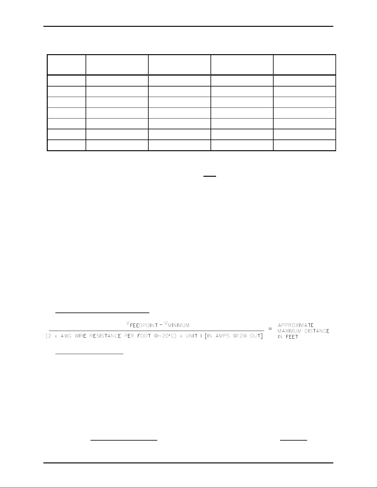
Maximum Cable Distance in Feet*
Number of
Units
No. 14 AWG
Total / Between
No. 12 AWG
Total / Between
No. 10 AWG
Total / Between
No. 8 AWG
Total / Between
1 977 / 977 1,554 / 1,554 2,471 / 2,471 3,931 / 3,931
2 651 / 325 1,037 / 518 1,648 / 824 2,620 / 1,310
3 489 / 163 777 / 259 1,236 / 412 1,966 / 655
4 391 / 98 622 / 155 988 / 247 1,572 / 393
5 325 / 65 518 / 103 823 / 165 1,310 / 262
6 279 / 46 444 / 74 706 / 117 1,123 / 187
9 196 / 21 311 /34 494 / 55 786 / 87
*Based on the following assumptions:
Continuous tone (alarm) signals driving each station’s speaker amp to a maximum of 12 watts.
OTE: If the station is used for speech (audio) signals only, the distances stated above can be
N
multiplied by a factor of 2 because speech signals do not have the energy content that a
continuous tone has; therefore, they do not require as much average current and thus less cable IR
drop will result.
GAI-Tronics-supplied cable is used.
Wire resistance (ohms) is the nominal value for the applicable AWG at 1,000 feet of bare copper,
stranded wire @ 20º C (68º F). Wire resistance values used are as follows:
No. 14 AWG = ~2.525 ohms; No. 12 AWG = ~1.588 ohms; No. 10 AWG = ~0.999 ohm; No. 8 AWG = ~0.628 ohm
DC V at cable run’s feed point (Float charge of connected batteries) = ~26.6 V dc
DC V at the last unit in cable run = 21 V dc minimum
Station unit current draw (I) is the same regardless of the unit’s placement along the cable run for
ease of calculation. (1.1 amperes when unit is producing a 12-watt sine wave output.)
Distances reflect a 3% reduction for margin of error.
For conditions other than above, the following formula may be helpful in calculating the approximate
maximum distance for a SINGLE station.
For CONTINUOUS tone applications
For SPEECH operation only
, multiply the above result by a factor of 2.
with minimum distortion:
Example: What is the approximate maximum distance for a single dc station if the voltage feed is 27.5 V
dc and a No. 14 AWG wire is used @ 20º C?
Info:
No. 14 AWG @ 20º C = ~0.002525 ohm per foot 2 for LOOP R
V
FEEDPOINT
= 27.5 V dc
Solution:
(27.5 V – 21 V) / ((2 0.002525 ohm per foot) 1.1 amps)
= 6.5 / 0.005555
= 1,170 feet (for CONTINUOUS TONE
f:\standard ioms - current release\42004 instr. man uals\42004-162e.doc
08/13
signal), or up to ~2,340 feet (factor of 2) for SPEECH signals
Page 4

Pub. 42004-162E
Model 670-002 24 V DC Explosion-proof Speaker Station Page 4 of 9
Mounting
Refer to Pub. 42004-183, which is shipped with this unit. The suggested mounting height for all station
enclosures is 54 inches (137 cm) up to the centerline of the enclosure.
To maintain the explosion-proof integrity of these stations, all mounting hardware is located outside the
enclosure. The unit should be mounted using the two mounting straps that extend past the four corners of
the enclosure. See Figure 1.
3
Use the standard
bolts first, then the top bolts. The mounting strap design allows the station to be removed from its
mounting surface by removing only two of the bolts.
/8-inch bolts to secure the enclosure to the mounting surface. Secure the bottom two
NOTE
If this unit is to be used outdoors, it should be mounted inside a Model 10444-003
Weatherproof Non-metallic Enclosure, which is equipped with a front door. This enclosure has four
mounting feet in the four corners and is suitable for mounting to many surfaces.
Conduit Installa tion
Refer to Pub. 42004-183, which is shipped with this unit. This publication details how to maintain the
explosion-proof integrity of the station.
NOTE
External conduits in areas with Class I, Group C and D areas must have gas seals
not more than 18 inches (457 mm) from the station enclosure. External cond uits in Class II and
Class III areas must have seals if the conduit system is not dust-tight.
Wir in g
After the station has been mounted, use a 7/16-inch wrench to open the front panel of the station to access
the Termination PCBA. Refer to Pub. 42004-183 for wiring details.
Feed the wiring through the conduit and into the enclosure. Follow the wire colors carefully—these
colors correspond to GAI-Tronics 60029 or 60038 Series cable. The wires must be spade-lugged and
connected carefully and completely to the terminal block. An improper termination may result in
diminished station performance.
Before closing the station, plug the power interconnect cable from the front of the enclosure into the
connector on the power supply card in the rear enclosure.
NOTE
All the bolts must be installed to maintain the integrity of the explosion-proof
construction.
f:\standard ioms - current release\42004 instr. man uals\42004-162e.doc
08/13
Page 5

Pub. 42004-162E
Model 670-002 24 V DC Explosion-proof Speaker Station Page 5 of 9
Figure 1. Model 670-002 Mounting Details
f:\standard ioms - current release\42004 instr. man uals\42004-162e.doc
08/13
Page 6

Pub. 42004-162E
Model 670-002 24 V DC Explosion-proof Speaker Station Page 6 of 9
Speaker Muting Information
This station is equipped with a muting feature that is used if the station is located near other
handset/speaker stations. This feature prevents acoustic feedback between stations during paging by
muting the station’s associated speaker. This station is shipped from the factory with the mute feature
enabled.
To disable the muting feature, remove jumper W6 located on the 10489-002 Termination PCBA. The
chart below describes how the muting function operates when specific combinations of wire jumpers W3,
W4, W5, and W6 are installed on the Termination PCBA.
W3 W4 W5 W6 Description of Operation
O
X X X
AUX/PAGE inputs to the amplifier are muted during station page (as
shipped from GAI-Tronics—see the note).
O
O
X X
X X
X
O
O
O AUX/PAGE inputs to the amplifier are not muted during a station page.
X
PAGE input is muted only during a station page.
X
PAGE input is muted during a station page or by contact closure between
the Mute A and B inputs.
X
O
X X
PAGE/AUX inputs are muted during a station page or by contact closure
between the Mute A and B inputs.
X
O O O PAGE/AUX inputs are not muted. Isolated normally open relay contact
output between the Mute A and B terminals is closed during station pages.
X = Installed O = Not Installed.
Mutual Muting
NOTE: Jumpers W4, W5, and W6 must be installed.
Stations that are located closely together may require mutual muting of the page amplifiers. To
accomplish mutual muting between stations, connect the orange (spare) wire in the GAI-Tronics station
cable to TB2-A on each of the Div. 1 stations that require muting. All the mutually muted stations are
muted when any connected station is paging.
Mutual muting can be accomplished between the Div. 1 stations and Div. 2 enclosures using most
GAI-Tronics 600 or 700 Series enclosures by connecting the orange (spare) wire between TB2-11(A) on
the Div. 1 station and TB1-7 on the Div. 2 enclosure:
Div. 1 Stations
(TB2-A)
Div. 2 Enclosures (TB1-7)
670-002 702-002 733-002 703-002
780-002 732-102 7335-002
7805-002 7325-102 758-002
Consult GAI-Tronics for any enclosures not listed.
OTE: The auxiliary speaker amplifier input is a balanced 10-kilohm audio input.
N
f:\standard ioms - current release\42004 instr. man uals\42004-162e.doc
08/13
Page 7

Pub. 42004-162E
Model 670-002 24 V DC Explosion-proof Speaker Station Page 7 of 9
Specification s
Power input ......................................................... 21–29 V dc; 1.2 A (optional negative ground or floating)
Dimensions ............................................................. 13.1 H 7.9 W 5.6 D inches; (332 200 143 mm)
Temperature range ............................................................................ −22° F to +158° F (−30° C to +70° C)
Shipping weight .................................................................................................................... 27 lbs. (12.2 kg)
Speaker Amplifier
Output ....................................................................... @ 25 V dc: 12 watts minimum into 8- or 16-ohm load
Voltage gain ........................................................................................................ 20 dB minimum, adjustable
Frequency response ............................................................................. 250–4,000 Hz, +0/−3 dB ref @ 1 kHz
Distortion ............................................................................................ 1% maximum THD @ 1 kHz/12 watt
Input impedance .......................................................................................... 50,000 ohm, minimum @ 1 kHz
Controls ................................................................................................................................. Speaker volume
Explosion-proof Enclosure
Material/finish ...................................................................................................... No. 359.2 Aluminum alloy
Mounting ...................................................................... Wall or column, four 3/8-inch slotted mounting feet
Connections................................................................................. Internal screw-type barrier terminal blocks
Conduit entries ...................................................................................................... Standard top: ¾-inch NPT
Standard bottom: 1.5-inches NPT
Optional bottom: 2-inch NPT
Approvals
NRTL certified for use in US and Canada for the following locations: ...... Class I, Div. 1, Groups C and D
Class II, Div. 1, Groups E, F, and G
Class III, Div. 1
REPLACEMENT PARTS
Part No. Description
12604-004 Fuse, 2-amp (pack of 10)
61514-005 Harness Assembly
12542-001 Replacement Front Cover Bolts (pack of 14)
69488-106 PCBA, Handset/Speaker Amplifier
69489-002 PCBA, Termination
12571-001 Maintenance Cover Kit
f:\standard ioms - current release\42004 instr. man uals\42004-162e.doc
08/13
Page 8

Pub. 42004-162E
Model 670-002 24 V DC Explosion-proof Speaker Station Page 8 of 9
f:\standard ioms - current release\42004 instr. man uals\42004-162e.doc
08/13
Page 9

Pub. 42004-162E
Model 670-002 24 V DC Explosion-proof Speaker Station Page 9 of 9
f:\standard ioms - current release\42004 instr. man uals\42004-162e.doc
08/13
Page 10

Warranty
Equipment. GAI-Tronics warrants for a period of one (1) year from the date of shipment, that any
GAI-Tronics equipment supplied hereunder shall be free of defects in material and workmanship, shall
comply with the then-current product specifications and product literature, and if applicable, shall be fit
for the purpose specified in the agreed-upon quotation or proposal document. If (a) Seller’s goods prove
to be defective in workmanship and/or material under normal and proper usage, or unfit for the purpose
specified and agreed upon, and (b) Buyer’s claim is made within the warranty period set forth above,
Buyer may return such goods to GAI-Tronics’ nearest depot repair facility, freight prepaid, at which time
they will be repaired or replaced, at Seller’s option, without charge to Buyer. Repair or replacement shall
be Buyer’s sole and exclusive remedy. The warranty period on any repaired or replacement equipment
shall be the greater of the ninety (90) day repair warranty or one (1) year from the date the original
equipment was shipped. In no event shall GAI-Tronics warranty obligations with respect to equipment
exceed 100% of the total cost of the equipment supplied hereunder. Buyer may also be entitled to the
manufacturer’s warranty on any third-party goods supplied by GAI-Tronics hereunder. The applicability
of any such third-party warranty will be determined by GAI-Tronics.
Services. Any services GAI-Tronics provides hereunder, whether directly or through subcontractors,
shall be performed in accordance with the standard of care with which such services are normally
provided in the industry. If the services fail to meet the applicable industry standard, GAI-Tronics will
re-perform such services at no cost to buyer to correct said deficiency to Company's satisfaction provided
any and all issues are identified prior to the demobilization of the Contractor’s personnel from the work
site. Re-performance of services shall be Buyer’s sole and exclusive remedy, and in no event shall GAITronics warranty obligations with respect to services exceed 100% of the total cost of the services
provided hereunder.
Warranty Periods. Every claim by Buyer alleging a defect in the goods and/or services provided
hereunder shall be deemed waived unless such claim is made in writing within the applicable warranty
periods as set forth above. Provided, however, that if the defect complained of is latent and not
discoverable within the above warranty periods, every claim arising on account of such latent defect shall
be deemed waived unless it is made in writing within a reasonable time after such latent defect is or
should have been discovered by Buyer.
Limitations / Exclusions. The warranties herein shall not apply to, and GAI-Tronics shall not be
responsible for, any damage to the goods or failure of the services supplied hereunder, to the extent
caused by Buyer’s neglect, failure to follow operational and maintenance procedures provided with the
equipment, or the use of technicians not specifically authorized by GAI-Tronics to maintain or service the
equipment. THE WARRANTIES AND REMEDIES CONTAINED HEREIN ARE IN LIEU OF AND
EXCLUDE ALL OTHER WARRANTIES AND REMEDIES, WHETHER EXPRESS OR IMPLIED BY
OPERATION OF LAW OR OTHERWISE, INCLUDING ANY WARRANTIES OF
MERCHANTABILITY OR FITNESS FOR A PARTICULAR PURPOSE.
Return Policy
If the equipment requires service, contact your Regional Service Center for a return authorization number
(RA#). Equipment should be shipped prepaid to GAI-Tronics with a return authorization number and a
purchase order number. If the equipment is under warranty, repairs or a replacement will be made in
accordance with the warranty policy set forth above. Please include a written explanation of all defects to
assist our technicians in their troubleshooting efforts.
Call 800-492-1212 (inside the USA) or 610-777-1374 (outside the USA) for help identifying the
Regional Service Center closest to you.
(Rev. 10/06)
 Loading...