

Page 1

Pub. 42004-216B
GAI-TRONICS® CORPORATION
A HUBBELL COMPANY
Model 476-002
Centra-Page Flush-Mount Station
Confidentiality Notice
This manual is pr ovided s olely as a n op erat ional, installation, and maintenance guide and contains sens itive
bus ines s and t echnic al infor ma tion tha t is confident i al and p roprietary to G AI-Tronics. GAI-Tronics
retains a ll intellectual pr operty and other rights in or to t he inf ormation c ontained herein, and s uch
informa tion may only be used in connection wit h the operation of you r GAI- Tronic s pr oduct or system.
This ma nual may not be disclosed in any form, in whole or in p art, dir ec tly or indirectly, to any t hird pa rty.
Introduction
GAI-Tronics Centra- Page s ystems provide dependable p aging and party line communica tions for ru gged
and ha z ardous indus trial fac ilities. Centr a-Page systems feature centrally loc ated electronics that provide
environmental p rotection and unitized amplific ation for eas y ma intenance. Sta ndard Centra-P age cab inets
can support up to 30 handset stations and, in most cases, up to 60 paging speakers. Alarms and telephone
interf acing can als o be added to Centra-P age systems.
The Model 476-002 Flush-Mount Station is used for paging and party line communications. When
installed in accordance with a control drawing 72979, the statio n pro v ide s intrinsically-safe o p er at io n
in Class I, Div. 1, Groups C and D hazardous areas. The station is equipped with a push-to-page
handset and part y line s elector.
General Information
The Model 476-002 Flush-Mount Station is enclosed in a metallic hous i ng with a front panel measuring 6
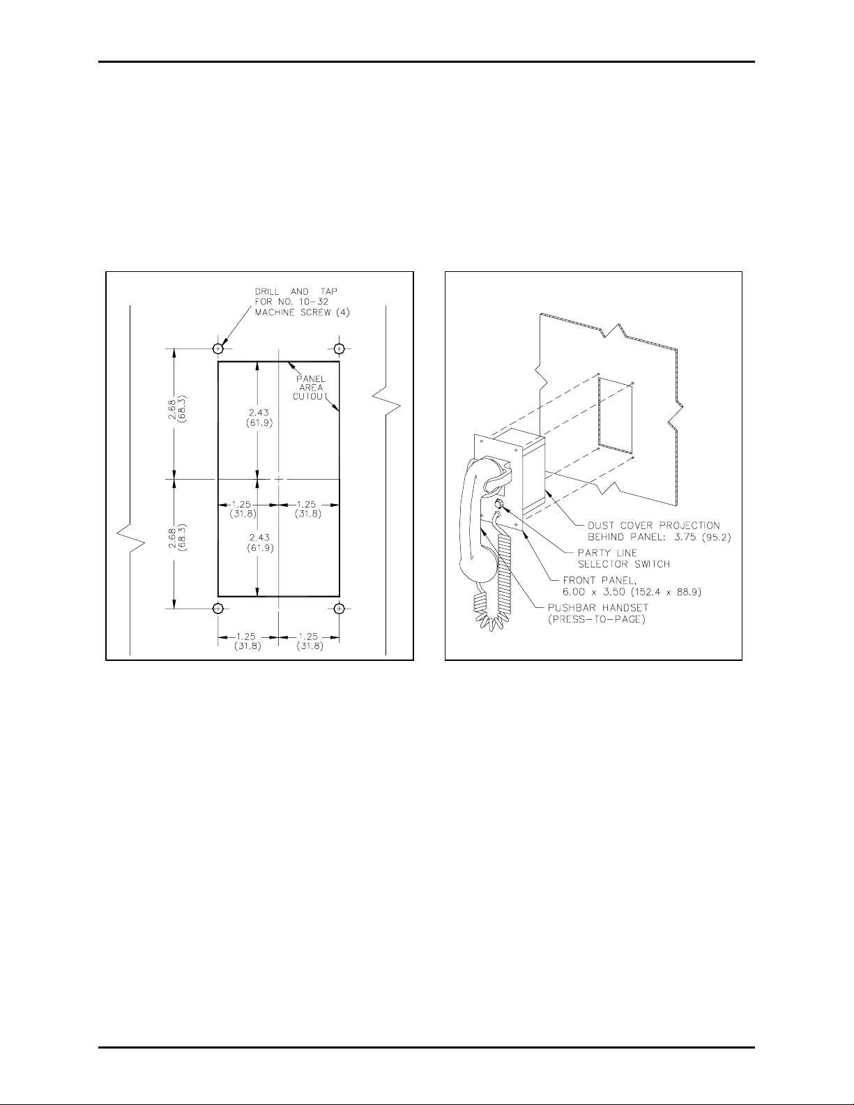
H × 3.5 W inches. S ee F igure 1 f or the dimensions of the wall cu tout needed for f l ush mounting the
station.
Although t here is no absolute limit on the number of sta tions in simu ltaneous use on a given int ercom path
(pa rty line 1 or 2) f or a conference-type call, the effectiveness of the sidetone r eject ion c i rcuit diminishes
and overall per f ormance b egins to diminish after four or more stations are connected together . Therefore, it
is recommended that conference-call pa rty line conver sat ions be limited to four simultaneous users.
GAI-Tronics Corporation P.O. Box 1060, Reading, PA 19607-1060 USA
610-777-1374 800-492-1212 Fax : 610-796-5954
ISIT WWW.GAI-TRONICS.COM FOR PRODUCT LITERATURE AND MANUALS
V
Page 2
Pub. 42004-216B
Model 476-002 Centr a- P age Flush-Mount St ation Page:
2 of 7
The Model 476-002 Station, like other Centra-Page stations, operates in conjunction with a plug-in Line
Card PCBA housed in the central cabinet card rack assembly. The line cards are sold separately. The card
contains the handset dc power source, dual - switching relays, and a 16-wat t speaker a mplifier with 8-ohm
and 70-volt line outputs.
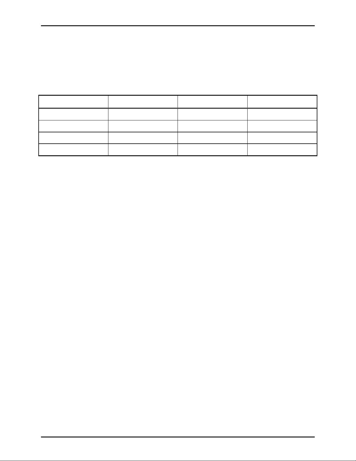
If installing t his station a s an add-on, p l ease consu l t the following chart to ensure prop er power is sup plied.
Power Supply Current Requirements in Amps
Mode 10 Cards 20 Cards 30 Cards
Standby 0.8 1.5 2.3
Page (Full load) 5.7 11.4 17.1
Alarm (Typical) 3.8 7.5 11.3
Alarm (Max. Level) 12.5 25.0 37.5
NOTES:
1. Ra tings at 27.0 V dc at c entral cabinet. Add 8% for page and alarm at 28.8 V dc .
2. Full load is defined as 15-watt load on all cards with levels as adjusted at f actory; 2 - watt alarm outp u t.
3. Typ ic al load is defined as 7.5 - watt load (such as 16- ohm loudspeaker connected t o 8 -ohm output).
4. Maximum level is defined as 15 - watt loads a nd level cont rol adju sted for 15-wa tt a larm level on all
cards.
5. Ra tings for alarm based on cont inuous tones. Pulse tone reduces c urrent to about 60% .
\\s_eng\gtc proddoc s \ s t andard iom s - current release\42004 inst r. m anuals \ 42004-216b. doc
08/05
Page 3
Pub. 42004-216B
Model 476-002 Centr a- P age Flush-Mount St ation Page:
3 of 7
Installation
Mounting
Please refer to Figu re 1 a nd Figure 2 for mounting details. The station has four mounting holes on the
front panel, and is supp lied wit h an opening for cab l e. Figure 1 shows the requ ired dimensions for the wall
cutout, and Figure 2 shows how to fit the f lush-mount station into the cutout. When mounting the station,
use caution to avoid damaging the component s inside.
Figure 1. Cutout Dimensions
\\s_eng\gtc proddoc s \ s t andard iom s - current release\42004 inst r. m anuals \ 42004-216b. doc
08/05
Figure 2. Mounting of Model 476-002 Station
Page 4

Pub. 42004-216B
Model 476-002 Centr a- P age Flush-Mount St ation Page:
4 of 7
Wiring
The configuration of the cable coming into the Model 476-002 depends on the chosen wiring method. For
additional information, refer to Pub. 42004-356, Centra-Page Control Drawing 72979, and Pub 42004222, Model 10468-002 Centra-Page Central Cabinet. Figure 3 below illustrates t he wiring termina tions
inside the Model 476-002 Station.
Ter mina tions L1, L2, P , and A c orres pond to identical ter minations at t he card rac k assembly. Thes e four
connections must be complet e as two pair . The fi rst pair , L1 and L2, ser ves as both the communications
path and the power supply. The second (control) p air provides p arty line selection or page line a c tivation.
Ter mina tions M1 and M2 are not used in t ypical insta llation.
The speaker c onductors a re connected directly to the as sociated spea ker or driver.
Installing a Model 476-002 in a Division 1 area requires that the four station conductors terminate in a
safety barrier (10439-102) prior to entering the Division 1 area. This configuration creates intrinsically
safe wiring to the station. Speaker wiring may not pass through the station. Refer to Pub. 42004-356
Control Drawing 72979 for proper installation.
The wiring distance limitation for a handset station is specified as 10,000 feet without a hazardous area
safety barrier, and 3,000 feet with a barrier. This distance is determined by degradation from cable
cap acitance more tha n c able r es ista nce: the use of heavier wire will not fu lly c ompens ate for a gr eater
distance.
Figure 3. Station Wiring Deta ils
\\s_eng\gtc proddoc s \ s t andard iom s - current release\42004 inst r. m anuals \ 42004-216b. doc
08/05
Page 5

Pub. 42004-216B
Model 476-002 Centr a- P age Flush-Mount St ation Page:
5 of 7
Adjustments
After the station is insta lled and wired, the page s peaker volu me may require adjust ment. This adjustment
cannot be made at the station, but rather a t the central cabinet /card rack. The pa ge speaker volume contr ol,
R1 through R10, is accessible on the rear of the Model 10461-002 Station Card Rack Assembly. Making
the adju stment r equ ires one per son near the spea ker and one a t the card rack in p arty line communicat ion.
1. Identify t he nu mber of the s tat ion c ard c onnected to be a djusted.
2. Lift the handset c onnected to any sta tion card except the one that is to be adjus ted. This st ep is
required only if tha t station is muted.
3. Adjust the control for the desired level while spea king into the handset with the handset press bar
depressed.
N
OTES:
• For alarm tone generation only
during rout ine p aging) r otat e t his control to the fully counterclockwise p osition.
• For telephone interface only
does NOT aff ect alarm signal levels.
: If the stat ion speaker is to broa dc ast only alarms, ( remains silent
: This control affects the level of the telephone inter f ace call “bir die” but
If yo u are assemblin g the C en tr a-Pa g e system in the fiel d , r efer to t h e spec i fic i n structio n manuals for
individual c omponents, if used. These manuals explain in detail how to ins tall and connect t he variou s
components of a Cent ra- Page s ystem. The manua ls for these components are lis ted below:
Pub. Number Component/Title
42004-214 Model 476-002 Centra-Pa ge Outdoor Wall St ation
42004-215 Model 472-002 Centra-Page Permanent Indoor 2-P arty St ation
42004-220 Model 10461-002 Centra-Pa ge Card Rack
42004-221 Model 69037-101 Centra-Pa ge Station Card
42004-227 Model C83018 Centra-Page Station Crew’s Quarters Muting Card
42004-222 Model 10468-002 Centra-Page Central Cabinet
42004-345 Model 10959-006 Rack-Mount Audio Messenger Interface
42004-371 Model 10961-001 AMI Centra-Page Interface
\\s_eng\gtc proddoc s \ s t andard iom s - current release\42004 inst r. m anuals \ 42004-216b. doc
08/05
Page 6

Pub. 42004-216B
Model 476-002 Centr a- P age Flush-Mount St ation Page:
6 of 7
Operation
1. To generate a page, lif t the handset, and check for an a vailable party line.
2. Pr es s the handset pressb ar, and announce t he p age indicating which page line to use. The page is heard
over the system speakers.
3. Release the pressbar and wait for a reply.
4. The paged individual goes to a handset s tat ion, uses the page line select or to s elect the specif ied p arty
line, and lif ts the handset t o reply. Full-du plex communication can then take p lace.
Specifications
Electrical
Handset:
Microphone.................................................... 10 ohms; pressure differential, noise-canceling dynamic
Receiver.................................................... 150 ohms; high efficiency dynamic, hearing aid c ompatible
Cable................................................................................... Retractile, 6 feet (1.82 m) extended PVC
Material ..................................................................................................................... L ight gray ABS
Controls................................................................................................................... Handset pressbar
Frequency response................................................................................................ 200-2,000 Hz, +/-3 dB
Distortion.......................................... Microphone input to r eceiver output 2% ( nomina l line level a t 1 kHz
Sidetone rejection................................................................................. 14 dB (nominal line level at 1 kHz)
DC line current............................................................................................... Each handset: 8 mA typical
Mechanical
Construction/finish............................................................................. Cold-rolled steel/ gray baked enamel
External controls...................................................................................... Rotary party line selector switch
Mounting.................................................................................................................... Flush-mount in wall
Connections .............................................................................. Internal screw-type barrier terminal blocks
Operating temperature range................................................................ -22º F to +140º F (-30º C to 60º C)
Dimensions:
Front panel.............................................................................. 6 H × 3.5 W inches (152.4 × 88.9 mm)
Behind panel..................................................................................................... 3.75 inches (95.2 mm)
Cutout........................................................ 2.5 W × 4.86 H × 2.5 D inches (63.6 × 123.6 × 63.5 mm)
Shipping weight................................................................................................................. 6.8 lbs (3.1 kg)
Approvals
NRTL a ppr oved for us e in US and C anada for the following haz ardous loca tions:
Intrinsically safe for.............................................Class I, Div. 1, Groups C and D hazardous locations
when installed in accordance with Control Drawing No. 72979. Exia
Listed for use in...................................................Class I, Div. 2, Groups C and D hazardous locations
when installed in accordance with Control Drawing No. 72979
\\s_eng\gtc proddoc s \ s t andard iom s - current release\42004 inst r. m anuals \ 42004-216b. doc
08/05
Page 7

Pub. 42004-216B
Model 476-002 Centr a- P age Flush-Mount St ation Page:
Replacement Parts
Part Number Description
10450-004 Handset Assembly
13201-010 Handset Handle
13203-004 Transmitter Cap
13204-002 Receiver Cap
7 of 7
\\s_eng\gtc proddoc s \ s t andard iom s - current release\42004 inst r. m anuals \ 42004-216b. doc
08/05
Page 8

Warranty
Equipment. GAI-Tronics warrants for a period of one (1) year from the date of shipment, that any
GAI-Tronics equipment supplied hereunder shall be free of defects in material and workmanship, shall
comply with the then-current product specifications and product literature, and if applicable, shall be fit
for the purpose specified in the agreed-upon quotation or proposal document. If (a) Seller’s goods prove
to be defective in workmanship and/or material under normal and proper usage, or unfit for the purpose
specified and agreed upon, and (b) Buyer’s claim is made within the warranty period set forth above,
Buyer may return such goods to GAI-Tronics’ nearest depot repair facility, freight prepaid, at which time
they will be repaired or replaced, at Seller’s option, without charge to Buyer. Repair or replacement shall
be Buyer’s sole and exclusive remedy. The warranty period on any repaired or replacement equipment
shall be the greater of the ninety (90) day repair warranty or one (1) year from the date the original
equipment was shipped. In no event shall GAI-Tronics warranty obligations with respect to equipment
exceed 100% of the total cost of the equipment supplied hereunder. Buyer may also be entitled to the
manufacturer’s warranty on any third-party goods supplied by GAI-Tronics hereunder. The applicability
of any such third-party warranty will be determined by GAI-Tronics.
Services. Any services GAI-Tronics provides hereunder, whether directly or through subcontractors,
shall be performed in accordance with the standard of care with which such services are normally
provided in the industry. If the services fail to meet the applicable industry standard, GAI-Tronics will
re-perform such services at no cost to buyer to correct said deficiency to Company's satisfaction provided
any and all issues are identified prior to the demobilization of the Contractor’s personnel from the work
site. Re-performance of services shall be Buyer’s sole and exclusive remedy, and in no event shall GAITronics warranty obligations with respect to services exceed 100% of the total cost of the services
provided hereunder.
Warranty Periods. Every claim by Buyer alleging a defect in the goods and/or services provided
hereunder shall be deemed waived unless such claim is made in writing within the applicable warranty
periods as set forth above. Provided, however, that if the defect complained of is latent and not
discoverable within the above warranty periods, every claim arising on account of such latent defect shall
be deemed waived unless it is made in writing within a reasonable time after such latent defect is or
should have been discovered by Buyer.
Limitations / Exclusions. The warranties herein shall not apply to, and GAI-Tronics shall not be
responsible for, any damage to the goods or failure of the services supplied hereunder, to the extent
caused by Buyer’s neglect, failure to follow operational and maintenance procedures provided with the
equipment, or the use of technicians not specifically authorized by GAI-Tronics to maintain or service the
equipment. THE WARRANTIES AND REMEDIES CONTAINED HEREIN ARE IN LIEU OF AND
EXCLUDE ALL OTHER WARRANTIES AND REMEDIES, WHETHER EXPRESS OR IMPLIED BY
OPERATION OF LAW OR OTHERWISE, INCLUDING ANY WARRANTIES OF
MERCHANTABILITY OR FITNESS FOR A PARTICULAR PURPOSE.
Return Policy
If the equipment requires service, contact your Regional Service Center for a return authorization number
(RA#). Equipment should be shipped prepaid to GAI-Tronics with a return authorization number and a
purchase order number. If the equipment is under warranty, repairs or a replacement will be made in
accordance with the warranty policy set forth above. Please include a written explanation of all defects to
assist our technicians in their troubleshooting efforts.
Call 800-492-1212 (inside the USA) or 610-777-1374 (outside the USA) for help identifying the
Regional Service Center closest to you.
(Rev. 10/06)
 Loading...