

Page 1

Pub. 42004-214C
GAI-TRONICS® CORPORATION
A HUBBELL COMPANY
Model 473-002
Centr a- Page Outdoor Wall Station
Confidentiality Notice
This manua l is provide d sole ly as an operatio nal, installation, and ma inte nance guide and conta ins
sensitive business and t e chnical informatio n tha t is confidentia l and pr opri et ary to GAI- Tronics.
GAI-Tronics retains all intellectual property and other rights in or to the information contained herein,
and such information may only be used in connection with the operation of your GAI-Tronics product or
system. This manu al may not be dis clos e d in any form, in whole or in pa rt, direct ly or i ndir ectly, to a ny
third pa r ty.
Introduction
The GAI-Tronics Centra-Page System provides dependable paging and party line communications for
rugged and hazardou s industrial f acilities. It feat ures c e ntrally l oc at e d electronics providing
environmental protection of components. A standard Centra-Page Central Cabinet can support up to 30
handset stations. Alarms and telephone interfacing can also be added to a Centra-Page system.
The Model 473-002 Outdoor Wall Station is used for paging and line communications. When installed
in accordance with control drawing No. 72979, the station provides intrinsically-safe operation in
Class I, Div. 1, Group C and D hazardous areas. Additionally, the station is listed for use in Class I,
Div. 2, Groups C and D; Class II, Div. 2, Gr oups F and G; and Class III, Div. 2 hazardous areas. The
station, which includes a push-to-pag e handset and a party li ne sele c tor , is hou sed i n a weatherproof
enclosure for outdoor installation.
General Information
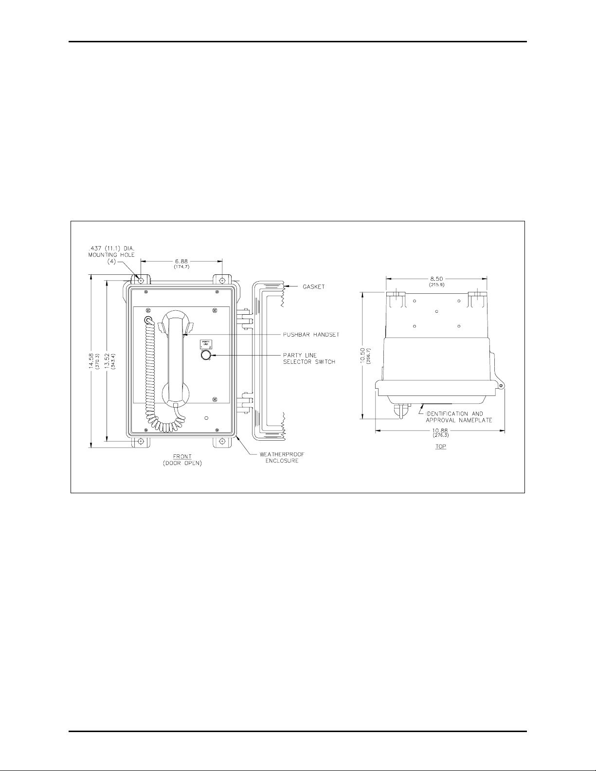
The Model 473-002 Outdoor Wall Station is housed in a non-metallic, weatherproof, Type 4X housing
measuring 6.88 W × 10.5 D × 14.58 H inches. See Figure 1 for the dimensions of the station mounting
holes located in the rear section.
Alth ough t h ere is no absolute limit o n the number of sta tions in simu ltan e ou s use on a give n intercom
path (party line 1 or 2) for a conference-type call, the effectiveness of the sidetone rejection circuit
diminishes and overall performance begins to diminish after four or more stations are connected together.
Therefore, it is recommended that conference-call party line conversations be limited to four simultaneous
users.
GAI-Tronics Corporation P.O. Box 1060, Readi ng, PA 19607-1060 USA
610-777-1374 800-492-1212 Fax: 610-796-5954
ISIT WWW.GAI-TRONICS.COM FOR PRODUCT LITERATURE AND MANUALS
V
Page 2
Pub. 42004-214C
Model 473-002 Centr a- P age Outdoor Wall Station Page: 2 of 7
The Model 473-002 Station, like other Centra-Page stations, operates in conjunction with a plug-in Line
Card PCBA housed in the central cabinet card rack assembly. The line cards are sold separately. The
card contains the handset dc power source, dual-switching relays, and a 16-watt speaker amplifier with
8-ohm and 70-volt line outputs.
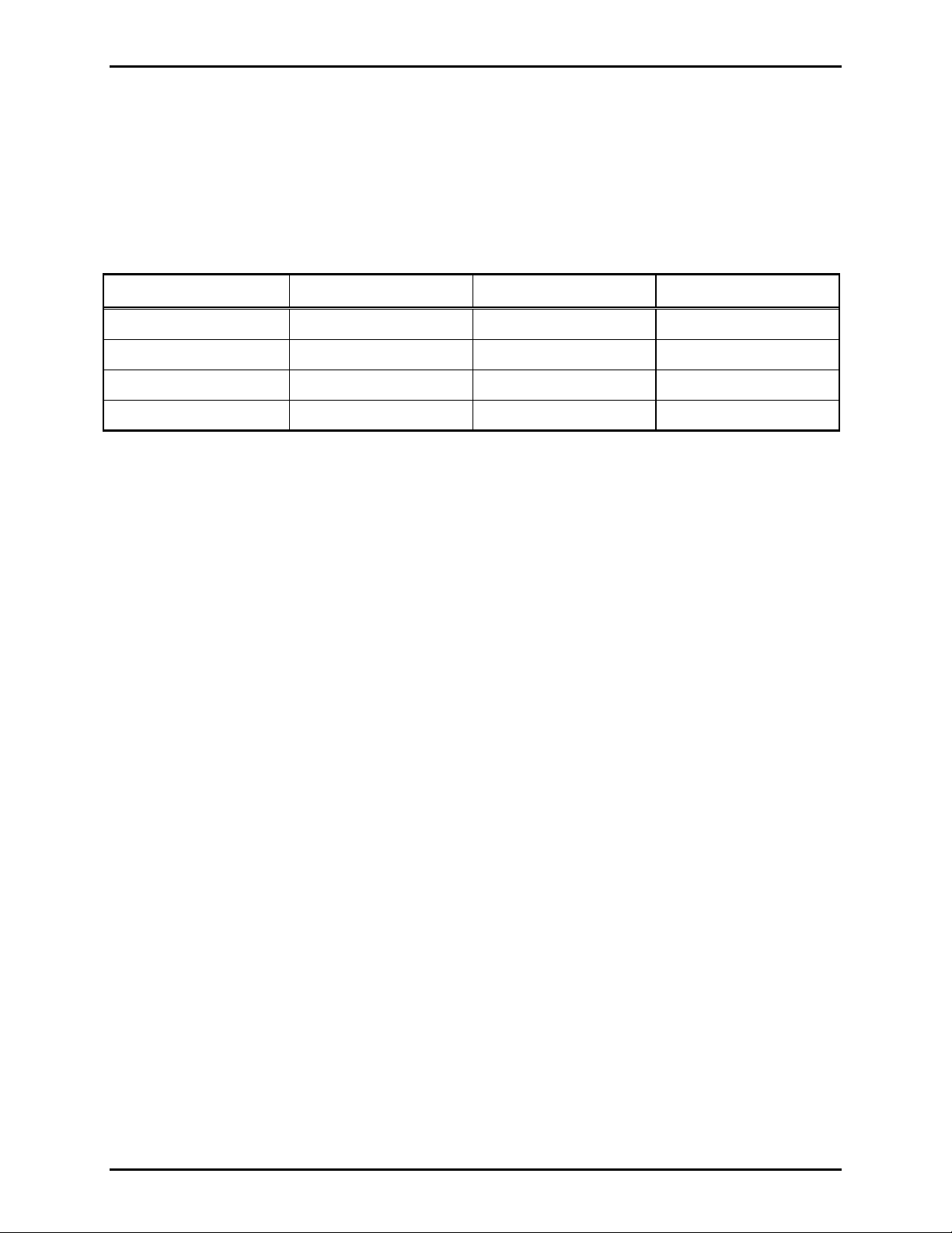
If installing this station as an add-on, please consult the following chart to ensure proper power is
supplied.
Power Supply Current Requirements in Amps
Mode 10 Cards 20 Cards 30 Cards
Standby 0.8 1.5 2.3
Page (Full load) 5.7 11.4 17.1
Alarm (Typical) 3.8 7.5 11.3
Alarm (Max. Level) 12.5 25.0 37.5
NOTES:
1. Ratings at 27.0 V dc at central cabinet. Add 8% for page and alarm at 28.8 V dc.
2. Full load is defined as 15-watt load on all cards with levels as adjusted at factory; 2-watt alarm
output.
3. Typical load is defined as 7.5-watt load (such as 16-ohm loudspeaker connected to 8-ohm output).
4. Max. level is defined as 15-watt loads and level control adjusted for 15-watt alarm level on all cards.
5. Ratings for alarm based on continuous tones. Pulse tone reduces current to about 60%.
\\s_eng\gtc proddoc s \st andard iom s - current release\42004 instr. manuals \ 42004-214c . doc
08/05
Page 3
Pub. 42004-214C
Model 473-002 Centr a- P age Outdoor Wall Station Page: 3 of 7
Installation
Mounting
Please refer to Figure 1 for mounting details. This station is not supplied with openings for conduit or
ca ble. Dr i ll or punch these o pening s b efore m o unting the encl o sure. The best place to put the cond uit
holes is along the bottom of the enclosure and near the rear surface.
There are four 0.437-inch (11.1 mm) diameter mounting holes in the four corners of the amplifier
enclosure. When mounting the enclosure, use caution to avoid damaging the terminal blocks inside. The
suggested mounting height for all station enclosures is 54 inches (1.37 m) to the center of the enclosure.
Figure 1. Station Outline and Mounting Details
Ensure that the gasket on the front panel is in place before mounting the station in the enclosure. The
gasket acts as spacer as well as a dust seal.
\\s_eng\gtc proddoc s \st andard iom s - current release\42004 instr. manuals \ 42004-214c . doc
08/05
Page 4

Pub. 42004-214C
Model 473-002 Centr a- P age Outdoor Wall Station Page: 4 of 7
Wiring
The configuration of the cable entering the Model 473-002 depends on the chosen wiring method. Refer
to Pub. 42004-356, Centra-Page Control Drawing No. 72979, and Pub. 42004-222, Model 10468-002
Centra-Page Central Cabinet for additional information. Refer to Figure 2 below for the wiring
terminations inside the Model 473-002 Outdoor Station.
Figure 2. Sta tion Internal Wiring Details
Terminations L1, L2, P, and A correspond to identical terminations at the card rack assembly. These four
connections must be complete as two pair. The first pair, L1 and L2, serves as both the communications
path and the power supply. The second (control) pair provides party line selection or page line activation.
Terminations M1 and M2 are not used in typical installation. The speaker conductors are connected
directly to the associated speaker or driver.
Installing the Model 473-002 in a Division 1 area requires that the four station conductors terminate in a
safety barrier (Model 10439-102) prior to entering the Division 1 area. This configuration creates
intrinsically safe wiring to the station. Speaker wiring may not pass through the station. Refer to Pub.
42004-356, Control Drawing 72979, for proper installation.
The w iring dista nce limita tion f or a handset station is spe c ified as 1 0,000 feet wi thou t a hazar dous ar ea
safety barrier, and 3,000 feet with a barrier. This distance is determined by degradation from cable
capacitance more than cable resistance. The use of heavier wire will not fully compensate for a greater
distance.
\\s_eng\gtc proddoc s \st andard iom s - current release\42004 instr. manuals \ 42004-214c . doc
08/05
Page 5

Pub. 42004-214C
Model 473-002 Centr a- P age Outdoor Wall Station Page: 5 of 7
Adjustments
After the s tat ion is instal led an d wir e d, the p age sp eake r volume may require adju stme nt. This adjustment
cannot be made at the station, but rather at the central cabinet/card rack. The page speaker volume
control, R1 through R10, is accessible on the rear of the Model 10461-002 Station Card Rack Assembly.
Making the adjustment requires one person near the speaker and one at the card rack in party line
communication.
1. Identify the number of the station card connected to be adjusted.
2. Lift the hands et of an y sta tion co nnected to a line card and make a page that is broadcast over a ll the
system speakers. If the station speaker being adjusted is muted, use a nearby station.
3. Continu e s peaking into th e handset with th e handset pr es sbar depressed while adjust ing the control
for the desired volume level.
OTES:
N
• For alarm tone generation only
during routine paging) rotate this control to the fully counterclockwise position.
• For telephone interface only
tone but will NOT affect alarm signal levels.
: If th e s tat ion speaker is to b roadc ast a larms only, ( remains silent
: This control affects the level of the telephone interface call “birdie”
If you are assembling the Centra-Page system in the field, refer to the specific instruction manuals for
individual components, if used. These manuals explain in detail how to install and connect the various
components of a Centra-Page syste m. The ma nuals f or these compone nts a re listed bel ow:
Pub. Number Component /Title
42004-215 Model 472-002 Centra-Page Permanent Indoor 2-Party Station
42004-216 Model 476-002 Centra-Page Flush-mount Station
42004-220 Model 10461-002 Centra-Page Card Rack
42004-221 Model 69037-101 Centra-Page Station Card
42004-227 Model C83018 Centra-Page Station Crew’s Quarters Muting Card
42004-222 Model 10468-002 Centra-Page Central Cabinet
42004-345 Model 10959-006 Rack-Mount Audio Messenger Interface
42004-371 Model 10961-001 AMI Centra-Page Interface
\\s_eng\gtc proddoc s \st andard iom s - current release\42004 instr. manuals \ 42004-214c . doc
08/05
Page 6

Pub. 42004-214C
Model 473-002 Centr a- P age Outdoor Wall Station Page: 6 of 7
Operation
1. To ge nera te a pa ge, lift the handset, and che ck for an ava ilab le party lin e.
2. Press the handset pressbar, and announce the page indicating which page line to use. The page is
heard over the system speakers.
3. Release the pressbar and wait for a reply.
4. The paged indi vidua l goes to a handset sta tion, uses t he pa ge line selector to sel ect th e s pecified p arty
line, and lifts the handset to reply. Full-duplex communication can then take place.
Specification s
Electrical
Handset:
Microphone:................................................. 10 ohms; pressure differential, noise-canceling dynamic
Receiver:................................................. 150 ohms; high-efficiency dynamic, hearing aid-compatible
Frequency response................................................................................................ 200-2000 Hz, +/-3 dB
Distortion.................................. Microphone input to receiver output 2% (nominal line level at 1,000 Hz)
Sidetone rejection.......................................................................... 14 dB (nominal line level at 1,000 Hz)
DC line current............................................................................................... Each handset: 8 mA typical
Mechanical
Construction/finish............................................................... Glass-reinforced polyester, hinged door with
neoprene gask et and c am-s tyle latch
External controls ..................................................................................... Rotary party line selector s wit ch
Handset:
Cable.................................................................................. Retractile, 6-foot (1.82 m) extended PVC
Material..................................................................................................................... Light gray ABS
Controls................................................................................................................... Handset pressbar
Mounting ................................................... Wall, column, or pole (mounting kit required for pole mount)
Four 0.437 inch (11.1 mm) diameter mounting holes
Connections ............................................................................ Internal screw-type barrier terminal blocks
Operating temperature range.................................................................. -22º F to 140º F (-30º C to 60° C)
Dimensions ........................................................ 14.6 H × 11.0 W × 10.0 D inches (356 × 280 × 254 mm)
Shipping weight ................................................................................................................ 13 lbs. (5.9 kg)
Environmental outdoor rating...................................................................................................... Type 4X
\\s_eng\gtc proddoc s \st andard iom s - current release\42004 instr. manuals \ 42004-214c . doc
08/05
Page 7

Pub. 42004-214C
Model 473-002 Centr a- P age Outdoor Wall Station Page: 7 of 7
Approval s
NRTL app roved for u se in US and C anada for the fol lowing ha z ardous loc ati ons:
Intrinsically safe for ............................................Class I, Div. 1, Groups C and D hazardous locations
when installed in accordance with control drawing No. 72979 Exia
Listed for use in................................................................................ Class I, Div. 2, Groups C and D;
Cla ss II , Div. 2 , Groups F a nd G; a nd
Class III, Div. 2 hazardous locations
when installed in accordance with control drawing No. 72979
Replaceme nt Parts
Part Numb e r Descrip tio n
10450-004 Handset Assembly
13201-010 Handset Handle
13203-004 Transmitter Cap
13204-002 Receiver Cap
\\s_eng\gtc proddoc s \st andard iom s - current release\42004 instr. manuals \ 42004-214c . doc
08/05
Page 8

Warranty
Equipment. GAI-Tronics warrants for a period of one (1) year from the date of shipment, that any
GAI-Tronics equipment supplied hereunder shall be free of defects in material and workmanship, shall
comply with the then-current product specifications and product literature, and if applicable, shall be fit
for the purpose specified in the agreed-upon quotation or proposal document. If (a) Seller’s goods prove
to be defective in workmanship and/or material under normal and proper usage, or unfit for the purpose
specified and agreed upon, and (b) Buyer’s claim is made within the warranty period set forth above,
Buyer may return such goods to GAI-Tronics’ nearest depot repair facility, freight prepaid, at which time
they will be repaired or replaced, at Seller’s option, without charge to Buyer. Repair or replacement shall
be Buyer’s sole and exclusive remedy. The warranty period on any repaired or replacement equipment
shall be the greater of the ninety (90) day repair warranty or one (1) year from the date the original
equipment was shipped. In no event shall GAI-Tronics warranty obligations with respect to equipment
exceed 100% of the total cost of the equipment supplied hereunder. Buyer may also be entitled to the
manufacturer’s warranty on any third-party goods supplied by GAI-Tronics hereunder. The applicability
of any such third-party warranty will be determined by GAI-Tronics.
Services. Any services GAI-Tronics provides hereunder, whether directly or through subcontractors,
shall be performed in accordance with the standard of care with which such services are normally
provided in the industry. If the services fail to meet the applicable industry standard, GAI-Tronics will
re-perform such services at no cost to buyer to correct said deficiency to Company's satisfaction provided
any and all issues are identified prior to the demobilization of the Contractor’s personnel from the work
site. Re-performance of services shall be Buyer’s sole and exclusive remedy, and in no event shall GAITronics warranty obligations with respect to services exceed 100% of the total cost of the services
provided hereunder.
Warranty Periods. Every claim by Buyer alleging a defect in the goods and/or services provided
hereunder shall be deemed waived unless such claim is made in writing within the applicable warranty
periods as set forth above. Provided, however, that if the defect complained of is latent and not
discoverable within the above warranty periods, every claim arising on account of such latent defect shall
be deemed waived unless it is made in writing within a reasonable time after such latent defect is or
should have been discovered by Buyer.
Limitations / Exclusions. The warranties herein shall not apply to, and GAI-Tronics shall not be
responsible for, any damage to the goods or failure of the services supplied hereunder, to the extent
caused by Buyer’s neglect, failure to follow operational and maintenance procedures provided with the
equipment, or the use of technicians not specifically authorized by GAI-Tronics to maintain or service the
equipment. THE WARRANTIES AND REMEDIES CONTAINED HEREIN ARE IN LIEU OF AND
EXCLUDE ALL OTHER WARRANTIES AND REMEDIES, WHETHER EXPRESS OR IMPLIED BY
OPERATION OF LAW OR OTHERWISE, INCLUDING ANY WARRANTIES OF
MERCHANTABILITY OR FITNESS FOR A PARTICULAR PURPOSE.
Return Policy
If the equipment requires service, contact your Regional Service Center for a return authorization number
(RA#). Equipment should be shipped prepaid to GAI-Tronics with a return authorization number and a
purchase order number. If the equipment is under warranty, repairs or a replacement will be made in
accordance with the warranty policy set forth above. Please include a written explanation of all defects to
assist our technicians in their troubleshooting efforts.
Call 800-492-1212 (inside the USA) or 610-777-1374 (outside the USA) for help identifying the
Regional Service Center closest to you.
(Rev. 10/06)
 Loading...