

Page 1

Pub. 42004-387G
GAI-TRONICS® CORPORATION
A HUBBELL COMPANY
Model 4512-001, 4512-001FR, 4514-001
and 4514-001FR 6-Channel Radios
User and Installation Manual
T ABLE OF C ONTENTS
Confidentiality Notice .....................................................................................................................1
General Information .......................................................................................................................1
Scope of Manual ...................................................................................................................................... 1
Features and Functions .......................................................................................................................... 1
Description ......................................................................................................................................2
Connectors ............................................................................................................................................... 3
Power Connector ................................................................................................................................................... 3
Speaker Connector ................................................................................................................................................ 4
Microphone Connector ......................................................................................................................................... 4
Antenna Connector ............................................................................................................................................... 4
Channel Selector Switch ......................................................................................................................... 4
Radio Transceiver Module ..................................................................................................................... 5
Interface PCBA ....................................................................................................................................... 5
Pot R7 ................................................................................................................................................................... 5
Wide Range (110/220 V AC/270 V DC) Power Supply PCBA ............................................................ 6
Pot 2 ...................................................................................................................................................................... 6
Surge Filter PCBA .................................................................................................................................. 6
Optional Standby/Emergency Battery .................................................................................................. 7
Installation ......................................................................................................................................8
Mounting .................................................................................................................................................. 8
FCC Interference Warning .................................................................................................................... 8
Safe Handling of CMOS Integrated Circuit Devices ........................................................................... 9
Equipment Required ............................................................................................................................ 10
Test Equipment ................................................................................................................................................... 10
Cable Installation Safety Considerations ............................................................................................ 10
Surge Protection .................................................................................................................................... 10
Antenna Connection ............................................................................................................................. 11
Power Connections ................................................................................................................................ 13
Models 4514-001 and 4514-001FR .................................................................................................................... 13
Models 4512-001 and 4512-001FR .................................................................................................................... 13
GAI-Tronics Corporation 400 E. Wyomissing Ave. Mohnton, PA 19540 USA
610-777-1374 800-492-1212 Fax: 610-796-5954
V
ISIT WWW.GAI-TRONICS.COM FOR PRODUCT LITERATURE AND MANUALS
Page 2

TABLE OF CONTENTS P UB. 42004-387G
Battery Connections .............................................................................................................................. 13
Microphone Connection ....................................................................................................................... 13
Speaker Connection .............................................................................................................................. 13
Programming......................................................................................................................................... 14
Power Supply Adjustment ................................................................................................................... 14
Speaker Output Adjustment ................................................................................................................ 14
Operation .......................................................................................................................................15
Initiating Calls ....................................................................................................................................... 15
Receiving Calls ...................................................................................................................................... 15
Controls .................................................................................................................................................. 15
Maintenance ..................................................................................................................................16
Ordering Replacement Parts ............................................................................................................... 16
Service and Repair ................................................................................................................................ 16
Troubleshooting .................................................................................................................................... 16
Fuse Replacement ................................................................................................................................. 17
Battery Replacement ............................................................................................................................ 17
Performance Specifications ..........................................................................................................18
Accessories ............................................................................................................................................. 19
Field Replacement Items ...................................................................................................................... 19
GAI-Tronics Corporation 400 E. Wyomissing Ave. Mohnton, PA 19540 USA
610-777-1374 800-492-1212 Fax: 610-796-5954
V
ISIT WWW.GAI-TRONICS.COM FOR PRODUCT LITERATURE AND MANUALS
Page 3

Pub. 42004-387G
GAI-TRONICS® CORPORATION
A HUBBELL COMPANY
Model 4512-001, 4512-001FR, 4514-001
and 4514-001FR 6-Channel Radios
Confidential ity Notice
This manual is provided solely as an operational, installation, and maintenance guide and contains
sensitive business and technical information that is confidential and proprietary to GAI-Tronics.
GAI-Tronics retains all intellectual property and other rights in or to the information contained herein,
and such information may only be used in connection with the operation of your GAI-Tronics product or
system. This manual may not be disclosed in any form, in whole or in part, directly or indirectly, to any
third party.
General Information
Scope of Manual
This manual provides descriptive data and service
information for the following GAI-Tronics 6-Channel
Radios:
Model 4512-001 - 270 V dc
Frequencies programmed by customer
Model 4514-001 - 110/220 V ac
Frequencies programmed by customer
Model 4512-001FR - 270 V dc
Frequencies programmed at the factory
Model 4514-001FR - 110/220 V ac
Frequencies programmed at the factory
Fea tures and Functions
Easy installation and maintenance
Portability with integral handle
Programmable CTCSS and DPL provided as standard
Heavy-duty industrial power supply and power line filter eliminates the need for external filtering
Selection of power sources, speakers, and antennas provides system configuration flexibility
Selectable 2-watt or 5-watt RF transmit power
High power receive audio and noise-canceling microphone for noisy environments
Figure 1. GAI-Tronics 6-Channel Radio
Standby/emergency battery option (integral to the chassis) providing continuous operation during
temporary power interruptions
GAI-Tronics Corporation 400 E. Wyomissing Ave. Mohnton, PA 19540 USA
610-777-1374 800-492-1212 Fax: 610-796-5954
V
ISIT WWW.GAI-TRONICS.COM FOR PRODUCT LITERATURE AND MANUALS
Page 4

Pub. 42004-387G
Model 4512-001, 4512-001FR, 4514-001, and 4514-001FR 6-Channel Radios Page 2 of 19
Description
The GAI-Tronics 6-Channel Radio is a stationary-mounted UHF transceiver suited for industrial
complexes, especially in cranes or other mobile equipment. It has a heavy-duty housing and includes a
choice of power sources (270 V dc or 110/220 V ac), microphones, speakers, and antennas. It has a
choice of 2-watt or 5-watt RF output, and CTCSS for private communications is selectable.
The radio measures 11.25 W 14.14 H 3.00 D inches. The housing is also a mounting bracket, and
includes an integral handle. The mounting bolts double as support feet when the unit is placed
horizontally on a flat surface such as on a desktop.
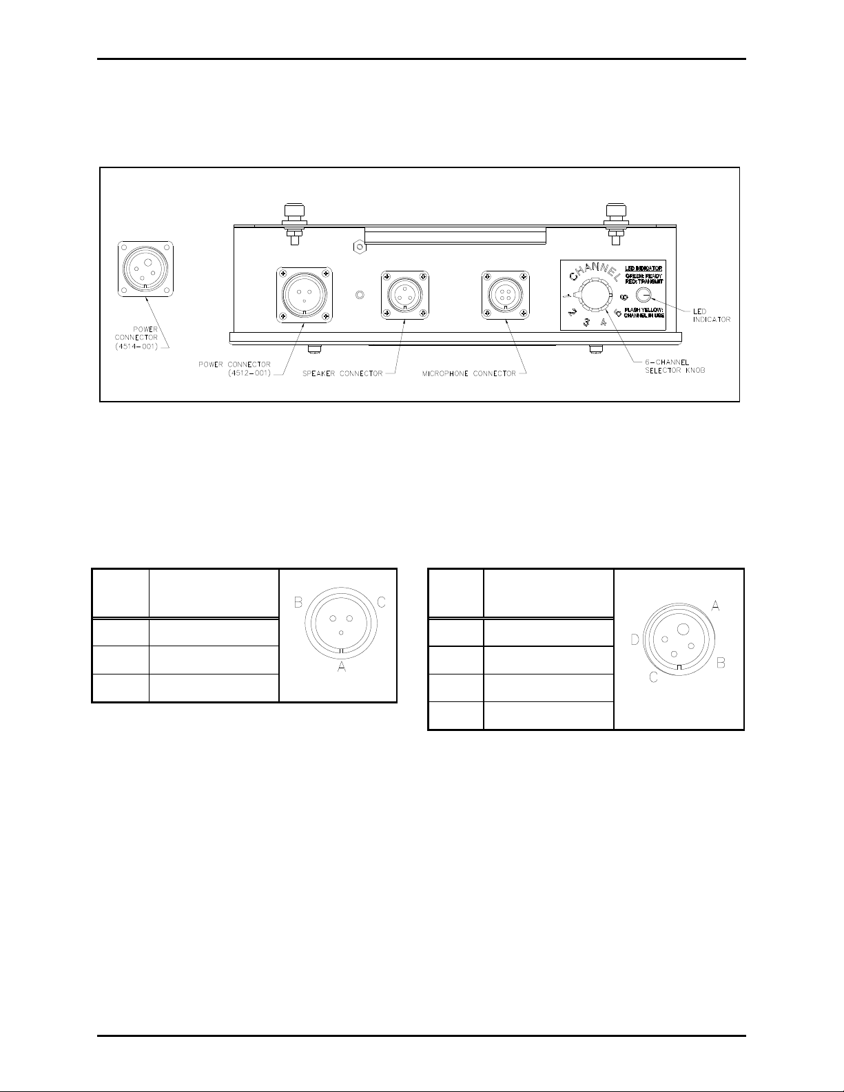
The channel selector switch and the power, speaker, and microphone connectors are located on the top of
the unit. The antenna connection is on the underside of the unit and remains easily accessible when the
unit is mounted. Refer to Figure 2 and Figure 3 below.
The standard power supply is nominal 120 V ac. There are 110/220 V ac or 270 V dc power supply
options available. Added filtering is standard for the 270 V dc option. The Radio Transceiver Module is
easily replaceable in the field, but must be reprogrammed by a qualified technician.
Figure 2. Outline of 6-Channel Radio
f:\standard ioms - current release\ 42004 instr. manuals\42004-387g.doc
02/15
Page 5
Pub. 42004-387G
Model 4512-001, 4512-001FR, 4514-001, and 4514-001FR 6-Channel Radios Page 3 of 19
Connectors
Refer to Figure 3 below for the location of the connectors and channel selector switch.
Figure 3. Top View of the 6-Channel Radio
Power Connector
Refer to Figure 3 for the locations of the connectors. The pinout for the power connector is as follows:
Table 1. Model 4512-001 Connector Pinout
Pin
No. Function
Pin
Table 2. Model 4514-001 Connector Pinout
No. Function
A Spare A Line hot
B 270 V dc pos B Line neutral
C 270 V dc neg C Spare
D Spare
f:\standard ioms - current release\ 42004 instr. manuals\42004-387g.doc
02/15
Page 6
Pub. 42004-387G
Model 4512-001, 4512-001FR, 4514-001, and 4514-001FR 6-Channel Radios Page 4 of 19
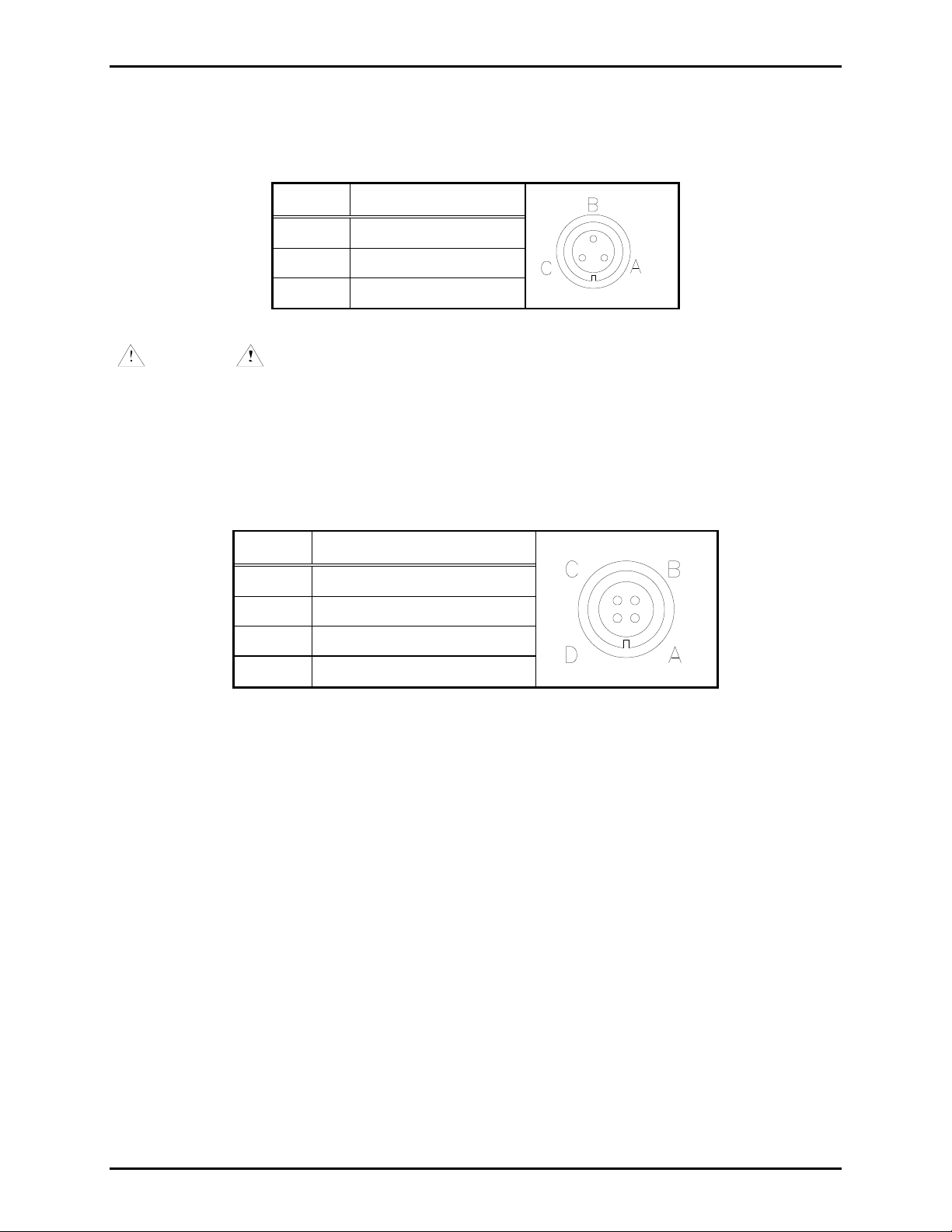
Speaker Connector
The speaker connector pinout is as follows:
Table 3. Speaker Connector Pinout
Pin No. Function
A Common
B Carrier detect output
C 8-ohm speaker
WARNING
Do not ground any speaker line as damage may occur to the speaker and/or
radio. Jumper P6 must be in position 2-3 to activate the carrier detect output. Refer to Table 6 on
page 5 and Figure 7 on page 12.
Microphone Connector
The microphone pinout is as follows:
Table 4. Microphone Connector Pinout
Pin No. Function
A Mic high
B PTT (Transmit key)
C Mic Lo
D 15 V dc power
Antenna Connector
The antenna connector is a coax cable connector.
Channel Selec tor Switch
The channel selector switch on the top of the unit allows easy selection among the six labeled channels.
In addition, a lighted LED provides indication of the state of the radio.
f:\standard ioms - current release\ 42004 instr. manuals\42004-387g.doc
02/15
Page 7

Pub. 42004-387G
Model 4512-001, 4512-001FR, 4514-001, and 4514-001FR 6-Channel Radios Page 5 of 19
Radio T ransceiver Mo dule
The Radio Transceiver Module’s range is 450–470 MHz, and the six channel frequencies can be
programmed in steps of 12.5 kHz at the factory to the customer’s specifications. The Radio Transceiver
can also be programmed for CTCSS or DPL.
NOTES:
1. When the Radio Transceiver Module is programmed for CTCSS or DPL it can only communicate with
other radios that have the same CTCSS or DPL programming.
2. Certain transmit and receive frequencies within the radio’s range are unavailable. Refer to Table 5
below for these frequencies. Do not attempt to program the radio for these frequencies.
Table 5. UHF (450–470 MHz)
Receive
(MHz)
Transmit
(MHz)
460.80000 460.78750
461.23750 460.79375
461.24375 460.80625
461.25625 460.81250
461.26250
Interface PCBA
The Interface PCBA contains four jumper settings, which can be configured in accordance with Table 6
below.
Table 6. Jumper Table
Jumper
Name Function
P1 Receive Audio Level Select 1-2 = High level
Position
2-3 = Low level attenuated 14 dB
Default
(as shipped)
1–2
P4 Audio Amp Enable 1-2 = Enable
1–2
2-3 = Disable
P5 Dynamic Mic/Carbon Mic Enable 1-2 = Enable
1–2
2-3 = Disable
P6 Optional Carrier Detect Output 1-2 = Disable
1–2
2-3 = Enable*
P8 RF Output Power Selection 1-2 = Low Power (2-watt)
1–2
2-3 = High Power (5-watt)
Pot R7
R7 is used to adjust the speaker level. Refer to Figure 4 on page 7 for the location of the pot. Refer to the
“Installation” section for instructions for speaker output adjustment.
f:\standard ioms - current release\ 42004 instr. manuals\42004-387g.doc
02/15
Page 8

Pub. 42004-387G
Model 4512-001, 4512-001FR, 4514-001, and 4514-001FR 6-Channel Radios Page 6 of 19
Wide Range (110/220 V AC/270 V DC) Pow er Supply PCBA
This switch-mode power supply features high-efficiency operation over an 85–300 V ac or dc input range.
The output is adjustable to provide proper float charging voltage to the optional standby battery.
The Power Supply PCBA provided as standard equipment maintains regulation per a wide range of input
voltages, and in addition to the internal protection, it is further protected from transients on the external
power source by the optional Surge Filter PCBA. The power supply provides regulated 12.5 V dc to the
radio circuits.
Pot 2
The Power Supply PCBA contains a pot adjustment, Pot 2, which is used to adjust the charging current
into the optional standby/emergency battery. Refer to Figure 4 on page 7 for the location of the pot.
Refer to the “Installation” section for instructions for the charging current adjustment.
Surge Filter PCBA
The Surge Filter PCBA provides additional power input filtering for noisy industrial 270 V dc power. It
is standard on the Models 4512-001 and the 4512-001FR only.
f:\standard ioms - current release\ 42004 instr. manuals\42004-387g.doc
02/15
Page 9

Pub. 42004-387G
Model 4512-001, 4512-001FR, 4514-001, and 4514-001FR 6-Channel Radios Page 7 of 19
Optional Standby/Emergency Battery
The GAI-Tronics 6-Channel Radios are designed to operate with a rechargeable battery. When installed,
the standby/ emergency battery supplies power for up to 15 minutes of normal run time with RF set to
low power setting; and less time if RF power is set to high power. The GAI-Tronics 40201-004 Battery is
sold separately. Refer to Figure 4 below for the locations of the internal components.
Figure 4. Internal Components of the 6-Channel Radio
f:\standard ioms - current release\ 42004 instr. manuals\42004-387g.doc
02/15
Page 10

Pub. 42004-387G
Model 4512-001, 4512-001FR, 4514-001, and 4514-001FR 6-Channel Radios Page 8 of 19
Installation
Figure 5. Sample Installation Diagram
Mounting
The radio can be placed horizontally on a desk or mounted vertically on a wall. To wall mount the radio,
remove the four bolts/support feet from the back of the housing. Mark the position of the housing, and
reinstall the bolts through the housing to a base plate or other suitable support.
FCC Interference Warning
The FCC requires that manuals pertaining to Class A and Class B computing devices must contain
warnings about possible interference with local residential radio and TV reception. This warning reads as
follows:
OTE: This equipment has been tested and found to comply with the limits for a Class A digital device,
N
pursuant to Part 15 of the FCC Rules. These limits are designed to provide reasonable protection against
harmful interference when the equipment is operated in a commercial environment.
This equipment generates, uses, and can radiate radio frequency energy and, if not installed and used in
accordance with the instruction manual, may cause harmful interference to radio communications.
Operation of this equipment in a residential area is likely to cause harmful interference in which case the
user will be required to correct the interference at his own expense.
f:\standard ioms - current release\ 42004 instr. manuals\42004-387g.doc
02/15
Page 11

Pub. 42004-387G
Model 4512-001, 4512-001FR, 4514-001, and 4514-001FR 6-Channel Radios Page 9 of 19
Safe Handling of CMOS Integrated Circuit Devices
Many of the integrated circuit devices used in communications equipment are of the Complementary
Metal Oxide Semiconductor (CMOS) type. Because of their high open circuit impedance, CMOS
integrated circuits are vulnerable to damage from static charges. Care must be taken handling, shipping,
and servicing them and the assemblies in which they are used.
Even though protection devices are provided in CMOS integrated circuit inputs, the protection is effective
only against overvoltage in the hundreds of volts range such as is encountered in an operating system. In
a system, circuit elements distribute static charges and load the CMOS circuits, decreasing the chance of
damage. However, CMOS circuits can be damaged by improper handling of the modules, even in a
system.
To avoid damage to circuits, observe the following handling, shipping, and servicing precautions:
1. Prior to and while servicing a circuit module, particularly after moving within the service area,
momentarily touch both hands to a bare metal, earth-grounded surface. This will discharge any static
charge that may have accumulated on the person doing the servicing.
OTE: Wearing a conductive wrist strap will minimize static build-up during servicing.
N
2. Whenever possible, avoid touching any electrically conductive parts of the circuit module with your
hands.
3. Power down the unit before installing or removing the circuit module.
4. When servicing a circuit module, avoid carpeted areas, dry environments, and certain types of
clothing (silk, nylon, etc.) because they contribute to static build-up. Similarly, disconnect the test
probe prior to removing the ground lead.
5. All electrically powered test equipment should be grounded. Apply the ground lead from the test
equipment to the circuit module before connecting the test probe.
6. If a circuit module is removed from the system, it is desirable to lay it on a conductive surface (such
as a sheet of aluminum foil) that is connected to ground through 100k of resistance.
7. When soldering, be sure the soldering iron is grounded with a grounded tip.
8. Prior to connecting jumpers, replacing circuit components, or touching CMOS pins (if this becomes
necessary in the replacement of an integrated circuit device), be sure to discharge any static build-up
as described in procedure 1. Since voltage differences can exist across the human body, it is
recommended that only one hand be used if it is necessary to touch pins on the CMOS device and
associated board wiring.
9. When replacing a CMOS integrated circuit device, leave the device in its conductive rail container or
conductive foam until it is to be inserted into the printed circuit module.
10. All low impedance test equipment (such as pulse generators, etc.) should be connected to CMOS
device inputs after power is applied to the CMOS circuitry. Similarly, such low impedance
equipment should be disconnected before power is turned off.
11. Replacement modules shipped separately from the factory will be packaged in a conductive material.
Any modules being transported from one area to another should be wrapped in a similar material
(aluminum foil may be used). Never use non-conductive material for packaging these modules.
f:\standard ioms - current release\ 42004 instr. manuals\42004-387g.doc
02/15
Page 12

Pub. 42004-387G
Model 4512-001, 4512-001FR, 4514-001, and 4514-001FR 6-Channel Radios Page 10 of 19
Equipment Required
Test Equipment
RF service monitor
AC voltmeter with dB ranges for measuring audio levels
#1 Phillips screwdriver
1/8-inch flat blade screwdriver
Cable Installation Safety Considerations
Interconnecting, communications, and Class 2 dc power cables should be separated from electrical light
or other Class 1 circuits by at least 2 inches. The exception is where Class 1 wiring or power circuits are
run in a raceway, or are metal-sheathed or metal-clad, or are permanently separated from the conductors
of the other circuitry by a continuous and firmly fixed nonconductor such as porcelain tubes or flexible
tubing in addition to the insulation on the wire. Communications cables and in-building wiring should be
listed and marked for the purpose according to NEC Article 800.
Surge Protection
The Model 4514-001 and 4514-001FR 6-Channel Radios (110/220 V ac) incorporate surge protection.
The power line fuse on the Power Supply module must be replaced with the same type fuse to maintain
safety protection.
Additional surge protection is available on the 4512-001 and 4512-001FR modules with additional safety
fusing. These fuses must also be replaced with the same type to maintain safety protection. See the
“Field Replacement Items” section.
f:\standard ioms - current release\ 42004 instr. manuals\42004-387g.doc
02/15
Page 13

Pub. 42004-387G
Model 4512-001, 4512-001FR, 4514-001, and 4514-001FR 6-Channel Radios Page 11 of 19
Antenna Connec tion
Select a Model CN3614 or similar antenna. Connect the antenna to the underside of the radio unit using
the 25-foot coax antenna cable. Refer to Figure 6 and Figure 7 for the Models 4512-001 and 4514-001
respectively.
Select an area for antenna mounting that gives the antenna an unobstructed view of the surrounding area.
Without proper line of sight to other antenna(s), TX and RX may be hindered. Antennas should be
mounted at least 3 feet from I-beams and metal bulkheads.
NOTE: Check the antenna with a wattmeter for proper standing wave ratio (SWR).
Figure 6. Model 4512-001 Connection Diagram
f:\standard ioms - current release\ 42004 instr. manuals\42004-387g.doc
02/15
Page 14

Pub. 42004-387G
Model 4512-001, 4512-001FR, 4514-001, and 4514-001FR 6-Channel Radios Page 12 of 19
Figure 7. Model 4514-001 Connection Diagram
f:\standard ioms - current release\ 42004 instr. manuals\42004-387g.doc
02/15
Page 15

Pub. 42004-387G
Model 4512-001, 4512-001FR, 4514-001, and 4514-001FR 6-Channel Radios Page 13 of 19
Power Connections
The power connections for all voltage options connect to the same MS connector on the top end of the
chassis. The power cord is not included. Refer to Figure 6 and Figure 7 for the respective models above.
CAUTION
Connect the power cable to the correct power source. Follow all the
appropriate National Electric Codes as well as local county and city electric codes.
Models 4514-001 and 4514-001FR
The black wire (pin A) is hot in the case of 110/220 V ac.
The white wire (pin B) is neutral or negative.
Models 4512-001 and 4512-001FR
The black wire (pin B) is positive in the case of 270 V dc.
The white wire (pin C) is negative.
Battery Connections
Install the GAI-Tronics 40201-004 Battery as follows. Refer to Figure 4 on page 7.
1. Loosen the mounting screw on the right of the 63069-013 Battery Bracket and lift it out of the
keyhole slot. Slide the battery into place. Replace the bracket and tighten the bracket screw.
2. The battery wire connections are parked on terminals TP1 and TP2 on the Power Supply PCBA.
3. Unplug the black wire from the Power Supply PCBA and slide onto (−) negative terminal of the
battery.
4. Unplug red wire from the Power Supply PCBA and slide onto (+) positive terminal of the battery.
OTE: If the battery is already charged, a small spark may occur when connecting the red wire. This
N
is normal.
Microphone Connection
Select a Model MI2895 or similar microphone. Install the microphone by plugging it in using the
appropriate connector on the top of the radio. R36 is the microphone volume adjustment.
Speaker Connection
Select a Model 13354-001 or similar speaker. Install the speaker by plugging it into the appropriate
connector on the top of the radio.
WARNING
Do not ground any speaker line as damage may occur to the speaker and/or radio.
f:\standard ioms - current release\ 42004 instr. manuals\42004-387g.doc
02/15
Page 16

Pub. 42004-387G
Model 4512-001, 4512-001FR, 4514-001, and 4514-001FR 6-Channel Radios Page 14 of 19
Programming
The Radio Transceiver Module contains programmable features, such as CTCSS and frequency selection,
which can be set at the factory to the customer’s specifications.
Any changes should be made by a qualified technician. The software programming kit (Part No. 19101-
024) is required.
Pow er Supply Adjustment
The power supply PCBA is factory-adjusted for a float voltage of 13.8 V dc at 11.5 mA charging current
into the optional standby/emergency battery. The charging current can be adjusted using Pot 2 on the
Power Supply PCBA. Refer to Figure 4 on page 7 for location of Pot 2. If field adjustment becomes
necessary, the procedure is as follows:
1. Disconnect the battery terminals and substitute a 1200-ohm, 5% resistor connected across the
‘fast-on’ terminals that are disconnected from the battery.
2. Measure across the resistor, and adjust the float level using Pot 2 to 13.8 +
3. Disconnect the load resistor and re-connect the leads of the battery.
0.1 V dc.
Speak er Output Adjustment
The speaker output volume is adjustable using R7 on the Interface PCBA. Refer to Figure 4 on page 7 for
the location of R7. The adjustment procedure is as follows:
1. With the speaker in place, initiate a radio conversation with a second radio user.
2. Adjust R7 for the desired maximum speaker volume.
f:\standard ioms - current release\ 42004 instr. manuals\42004-387g.doc
02/15
Page 17

Pub. 42004-387G
Model 4512-001, 4512-001FR, 4514-001, and 4514-001FR 6-Channel Radios Page 15 of 19
Operation
Use the microphone to operate the radio in a standard push-to-talk/release-to-listen mode. Choose among
the six channels by rotating the channel selector switch. Keep transmissions short to avoid tying up the
channel. Continuous transmissions longer than 30 seconds will be terminated by a built-in transmit limit
timer (TOT).
OTE: This setting can be factory adjusted.
N
Note that units programmed with the CTCSS or DPL can only carry on two-way communications with
units which have identical CTCSS or DPL programming.
Initiati ng Calls
1. To initiate a call, press the microphone button. Always allow a short delay before speaking to allow
time for the radio channel to be established.
2. Speak directly into the microphone held approximately 1/2 inch from the mouth. The microphone
button must be held down while talking to the radio user and released to listen.
N
OTE: The speaker is muted during transmission. To un-mute, move the shorting jumper P4 from
P4-1/P4-2 to P4-2/P4-3.
3. When the transmission is completed, the radio returns to the receive mode.
Receivi ng Calls
When power is applied, the radio is in the receive mode, allowing receive audio to be heard through the
speaker. The radio is always in receive mode unless the microphone button is pressed. To reply to a call,
wait until the caller has finished speaking, then press the microphone button and reply.
Controls
Use the rotary frequency switch on the top of the unit to select the radio channel. The multi-color LED
indicates the radio channel status.
Green: Indicates power is on/idle condition
Flashing yellow: Indicates channel activity (in use)
Red: Indicates transmitter on (PTT active)
f:\standard ioms - current release\ 42004 instr. manuals\42004-387g.doc
02/15
Page 18

Pub. 42004-387G
Model 4512-001, 4512-001FR, 4514-001, and 4514-001FR 6-Channel Radios Page 16 of 19
Maintenance
Ordering Replacement Parts
Include the complete identification number when ordering replacement parts or requesting equipment
information. This applies to all components, kits, and chassis. If the component part number is not
known, the order should include the number of the chassis or kit of which it is a part and sufficient
description of the desired component to identify it. Order parts from:
Customer Service
GAI-Tronics Corporation
400 E. Wyomissing Ave.
Mohnton, PA 19540
US: 800-492-1212
Outside US: 610-777-1374
Service and Re pair
Inoperative or malfunctioning equipment should be returned to the factory for repair. Please call
1-800-492-1212 or 610-777-1374 to obtain a Return Authorization number, published repair prices, and
shipping instructions.
OTE: A purchase order or credit card number is required prior to processing non-warranty repairs.
N
Troubleshooting
The following is a list of potential problems you may encounter and possible solutions.
Problem Possible Solution
The radio does not transmit. 1. Check to determine if logic low is reaching the radio via P7 pin 14.
2. Check to determine if power and ground are reaching the radio via P7
pin 6 and pin 15.
Radio is getting power,
ground, and PTT, but still
does not transmit.
There is no receive audio. 1. Ensure the P4 jumper is installed between pins 1–2
Replace radio module. Replacement and any necessary reprogramming
must be made by a licensed technician.
2. Check for audio signal at TB2 (speaker terminals).
f:\standard ioms - current release\ 42004 instr. manuals\42004-387g.doc
02/15
Page 19

Pub. 42004-387G
Model 4512-001, 4512-001FR, 4514-001, and 4514-001FR 6-Channel Radios Page 17 of 19
Fuse Repl acement
CAUTION
For continued safe operation, replace fuses with the same type
(See “Field Replacement Items” on page 19):
Power Supply PCBA fuse F1 1.25A, Slo-Blo, 2AG, 250V, axial-leaded, UL/CSA
Power Supply PCBA fuse F2 is 1.6A, Slo-Blo, 520mm, 250V, UL/CSA
Surge Filter PCBA fuses F4 and F5 are 2.0A, Slo-Blo, 520mm, 250V, UL/CSA
Interface PCBA fuses F1 and F3 are 1.0A, Slo-Blo, 520mm, 250V, UL/CSA
Interface PCBA fuse F2 is 0.1A, Slo-Blo, 520mm, 250V, UL/CSA
Battery Replacement
The optional standby/emergency battery is designed to have a shelf life of approximately 2 years, but
battery life may be reduced depending on use. The battery is automatically recharged during normal
radio usage. If the battery fails to operate the radio during a brief power interruption, the battery may
need to be replaced.
Replace the Part No. 40201-004 Battery as follows:
1. Slide the cable connectors off the top of the battery to disconnect.
2. Remove the screw on the right of the battery mounting bracket.
3. Slide the bracket up and lift it out of the keyhole slot.
4. Reverse the process to install the new battery.
f:\standard ioms - current release\ 42004 instr. manuals\42004-387g.doc
02/15
Page 20

Pub. 42004-387G
Model 4512-001, 4512-001FR, 4514-001, and 4514-001FR 6-Channel Radios Page 18 of 19
Perf ormance Specifications
Color ..................................................................................................................................................... Black
Construction .................................................................................................... Dust-resistant steel enclosure
Physical size ........................................................................................ 14.125 H 11.25 W 3.00 D inches
Weight .................................................................................................................................................. 10 lbs.
Temperature range .............................................................................................................. −30 ºC to +50 ºC
Humidity ...................................................................................................................... 90% non-condensing
270 V DC Option
Supply voltage range .................................................................... 200–350 V dc range, (270 V dc nominal)
Power consumed .................................................................................... 8 watts standby/30 watts maximum
Supply voltage filtering ....................................................................................... Two-stage LC, RES, MOV
110/220 V AC Opt ion
Supply voltage range ............................................... 85–260 V ac range, (50/60 Hz; 110/220 V ac nominal)
Power consumed .................................................................................... 8 watts standby/85 watts maximum
(with high-power RF setting) and battery charging
Speaker amplifier ........................................................................................... 8 watts maximum into 8 ohms
UHF Radio Transceiver
General
FCC ID .................................................................................................................................... AIERT17-445
Frequency range ...................................................................................................................... 450–470 MHz
Frequency stability ....................................................................................................................... +/−1.5 ppm
Tone/code signaling ....................................................................................... CTCSS (Quiet Call) and DCS
Transmitter
RF power output ......................................................................................................... 2.0 watts (low power)
5.0 watts (high power)
Spurious and harmonic frequencies ............................................................................... −20 dBm maximum
Receiver
Sensitivity 12 dB SINAD .................................................................................................................. 0.25 V
Inter-modulation ................................................................................................................................ −67 dB
Microphone .................................................................... No. MI2895 dynamic, amplified, noise-canceling
Speaker .................................................................................... No. 13354-001, 16-watt with volume control
Antennas ............................................................................................. No. CN3614 1/4 wave whip antenna
Emergency Battery Backup Option Run Time ................ 15 minutes typical power drain (low RF setting);
shorter with high-power RF setting
Models
4512-001 ........................................................................... 270 V dc; frequencies programmed by customer
4514-001 .................................................................... 110/220 V ac; frequencies programmed by customer
4512-001FR ........................................................................... 270 V dc; frequencies programmed at factory
4514-001FR .............................................................. 110/220 V ac; frequencies programmed at the factory
N
OTE: Customers are to supply frequencies to GAI-Tronics at the time of order.
f:\standard ioms - current release\ 42004 instr. manuals\42004-387g.doc
02/15
Page 21

Pub. 42004-387G
Model 4512-001, 4512-001FR, 4514-001, and 4514-001FR 6-Channel Radios Page 19 of 19
Accessories
Description Part No.
Microphone, Noise-Canceling MI2895
Wall-Mount Speaker 13354-001
Antenna with 25-Foot Coax Cable and Connector CN3614
UHF Ground Plate CH3272
6-Channel Radio to GAI-Tronics Page/Party® Coupler 370-400
Radio Programming Kit 19101-024
Battery, 1.3 AH, 12 V sealed rechargeable, lead-acid 40201-004
Field Replacement Items
Description Part No.
Fuse F1 (Power Supply PCBA) 1.25A, Slo-Blo, 2AG, 250V, axial-leaded, UL/CSA 4612-23015-25
Fuse F2 (Power Supply PCBA) 1.6A, Slo-Blo, 520mm, 250V, UL/CSA
Fuse F4 and F5 (Surge Filter PCBA) 2.0A, Slo-Blo, 520mm, 250V, UL/CSA
Fuse F1 and F3 (Interface PCBA) 1.0A, Slo-Blo, 520mm, 250V, UL/CSA
Fuse F2 (Interface PCBA) 0.1A, Slo-Blo, 520mm, 250V, UL/CSA
51809-007
51809-008
51809-006
51809-001
6-Channel Radio Power Supply PCBA 69316-202
6-Channel Radio Interface PCBA 69317-003
6-Channel Radio Surge Protector PCBA 69318-001
Protective Cap, 7/8-inch MC3761
Protective Cap, 1-1/8 inches MC3762
Synthesized UHF Transceiver Module 19101-046
f:\standard ioms - current release\ 42004 instr. manuals\42004-387g.doc
02/15
Page 22

Warranty
Equipment. GAI-Tronics warrants for a period of one (1) year from the date of shipment, that any
GAI-Tronics equipment supplied hereunder shall be free of defects in material and workmanship, shall
comply with the then-current product specifications and product literature, and if applicable, shall be fit
for the purpose specified in the agreed-upon quotation or proposal document. If (a) Seller’s goods prove
to be defective in workmanship and/or material under normal and proper usage, or unfit for the purpose
specified and agreed upon, and (b) Buyer’s claim is made within the warranty period set forth above,
Buyer may return such goods to GAI-Tronics’ nearest depot repair facility, freight prepaid, at which time
they will be repaired or replaced, at Seller’s option, without charge to Buyer. Repair or replacement shall
be Buyer’s sole and exclusive remedy. The warranty period on any repaired or replacement equipment
shall be the greater of the ninety (90) day repair warranty or one (1) year from the date the original
equipment was shipped. In no event shall GAI-Tronics warranty obligations with respect to equipment
exceed 100% of the total cost of the equipment supplied hereunder. Buyer may also be entitled to the
manufacturer’s warranty on any third-party goods supplied by GAI-Tronics hereunder. The applicability
of any such third-party warranty will be determined by GAI-Tronics.
Services. Any services GAI-Tronics provides hereunder, whether directly or through subcontractors,
shall be performed in accordance with the standard of care with which such services are normally
provided in the industry. If the services fail to meet the applicable industry standard, GAI-Tronics will
re-perform such services at no cost to buyer to correct said deficiency to Company's satisfaction provided
any and all issues are identified prior to the demobilization of the Contractor’s personnel from the work
site. Re-performance of services shall be Buyer’s sole and exclusive remedy, and in no event shall GAITronics warranty obligations with respect to services exceed 100% of the total cost of the services
provided hereunder.
Warranty Periods. Every claim by Buyer alleging a defect in the goods and/or services provided
hereunder shall be deemed waived unless such claim is made in writing within the applicable warranty
periods as set forth above. Provided, however, that if the defect complained of is latent and not
discoverable within the above warranty periods, every claim arising on account of such latent defect shall
be deemed waived unless it is made in writing within a reasonable time after such latent defect is or
should have been discovered by Buyer.
Limitations / Exclusions. The warranties herein shall not apply to, and GAI-Tronics shall not be
responsible for, any damage to the goods or failure of the services supplied hereunder, to the extent
caused by Buyer’s neglect, failure to follow operational and maintenance procedures provided with the
equipment, or the use of technicians not specifically authorized by GAI-Tronics to maintain or service the
equipment. THE WARRANTIES AND REMEDIES CONTAINED HEREIN ARE IN LIEU OF AND
EXCLUDE ALL OTHER WARRANTIES AND REMEDIES, WHETHER EXPRESS OR IMPLIED BY
OPERATION OF LAW OR OTHERWISE, INCLUDING ANY WARRANTIES OF
MERCHANTABILITY OR FITNESS FOR A PARTICULAR PURPOSE.
Return Policy
If the equipment requires service, contact your Regional Service Center for a return authorization number
(RA#). Equipment should be shipped prepaid to GAI-Tronics with a return authorization number and a
purchase order number. If the equipment is under warranty, repairs or a replacement will be made in
accordance with the warranty policy set forth above. Please include a written explanation of all defects to
assist our technicians in their troubleshooting efforts.
Call 800-492-1212 (inside the USA) or 610-777-1374 (outside the USA) for help identifying the
Regional Service Center closest to you.
(Rev. 10/06)
 Loading...