

Page 1

Pub. 42004-460A
GAI-TRONICS® CORPORATION
A HUBBELL COMPANY
Model 400-003 IEC/ATEX
Zone 1 RigCom Station
Confidential ity Notice
This manual is provided solely as an operational, installation, and maintenance guide and contains
sensitive business and technical information that is confidential and proprietary to GAI-Tronics.
GAI-Tronics retains all intellectual property and other rights in or to the information contained herein,
and such information may only be used in connection with the operation of your GAI-Tronics product or
system. This manual may not be disclosed in any form, in whole or in part, directly or indirectly, to any
third party.
General Information
GAI-Tronics Model 400-003 IEC/ATEX Zone 1 RigCom Station is designed for common-talk, or
master/slave communication system operation in IEC Zone 1 hazardous locations.
The unit provides push-to-talk, release-to-listen operation, and has a local on/off volume control switch to
activate and control the volume level for each station independently.
Model 400-003 has three M20 threaded entry holes for system, power, loudspeaker and optional remote
microphone and footswitch connection.
The Model 400-003 is designed to operate with other 400-003 stations, and GAI-Tronics EZ Page Series
of non-hazardous area rated equipment.
Figure 1. Model 400-003 RigCom Station
GAI-Tronics Corporation 400 E. Wyomissing Ave. Mohnton, PA 19540 USA
610-777-1374 800-492-1212 Fax: 610-796-5954
V
ISIT WWW.GAI-TRONICS.COM FOR PRODUCT LITERATURE AND MANUALS
Page 2

Pub. 42004-460A
Model 400-003 IEC/ATEX Zone 1 RigCom Station Page: 2 of 16
Important Safety Instructions
1. Read, follow, and retain instructions - All safety and operating instructions should be read and
followed before operating the unit. Retain instructions for future reference.
2. Comply with all warnings on the unit and in the operating instructions.
3. Attachments not recommended by the product manufacturer shall not be used as they may cause
hazards.
4. Do not attempt to service this unit yourself. Opening or removing covers may expose you to
dangerous voltage or other hazards. Refer all servicing to qualified service personnel.
5. Electrical and mechanical installation and connection should be in compliance with all regulations.
This permanently connected apparatus must have an ALL-POLE MAINS switch with a contact
separation of at least 3 mm in each pole incorporated in the electrical installation of the building.
Installation
These enclosures must be installed by trained, qualified and competent personnel. Installation must
comply with state and national regulations, as well as safety practices for this type of equipment.
CAUTION
on the approval listing in the “Specifications” section of this manual. Such installation may cause a
safety hazard and consequent injury or property damage.
The mounting location must be flat and provide proper clearance, rigidity and strength to support the
enclosure and all contained devices.
f:\standard ioms - current release\42004 instr. man uals\42004-460a.doc
09/12
Do not install this equipment in hazardous areas other than those indicated
Page 3

Pub. 42004-460A
Model 400-003 IEC/ATEX Zone 1 RigCom Station Page: 3 of 16
Securely fasten the enclosure to the mounting location, using (customer-supplied) 11-mm (7/16-inch)
diameter steel mounting bolts and washers, or washer head bolts.
WARNING
Insure proper grounding to protective earthing.
Do not disconnect equipment while energized.
Inspect and clean the machined flange flame joint surfaces of both the cover and box. Surfaces must be
smooth, free of nicks, scratches, dirt or any foreign particle build-up that would prevent a proper seal.
Surfaces must seat fully against each other to provide a proper explosion-proof joint. Clean surfaces by
wiping with a clean lint-free cloth.
Make certain no cover bolts are omitted. Use only those bolts supplied with the enclosure.
Recommended torque setting of cover bolts 17 ft-lbs. (23 N-m).
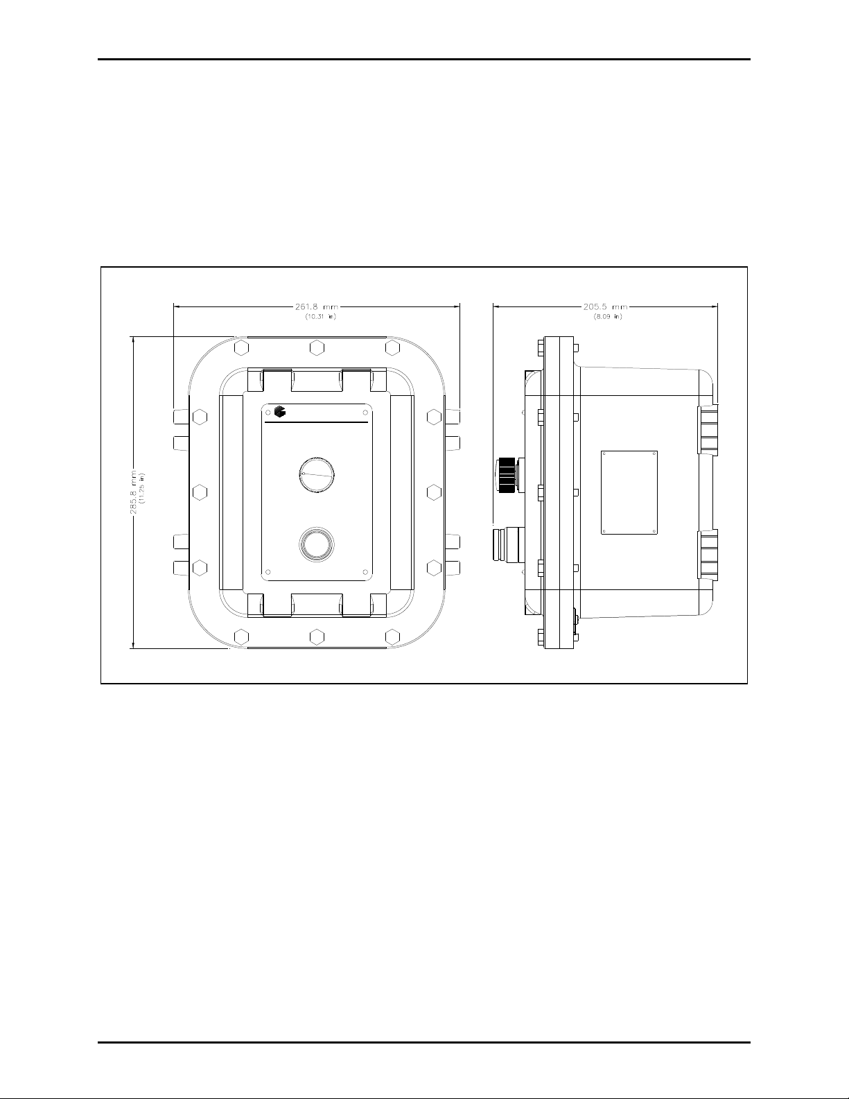
Mounting
NOTE: The mounting surface must be able to support the weight of the aluminum enclosure. The unit
weight is 23.0 lbs. (10.5 kg).
The enclosure must be securely fastened with 11-mm (7/16-inch) diameter steel mounting bolts located
on all four mounting feet. Stainless steel hardware is recommended for applications in corrosive
environments. Refer to Figure 2 for mounting dimensions.
Figure 2. Model 400-003 Mounting Details and Entries
f:\standard ioms - current release\42004 instr. man uals\42004-460a.doc
09/12
Page 4
Pub. 42004-460A
Model 400-003 IEC/ATEX Zone 1 RigCom Station Page: 4 of 16
Hardware Configuration
External
The enclosure contains a push-to-call push button, an on-off/volume control switch and applicable
approval labeling. There are twelve 5/16-18 1.25-inch cover mounting bolts located around the
perimeter of the enclosure.
The enclosure has an external grounding screw located on the underside of the flange. See Figure 2.
GAI-TRONICS CORPORATION
400 E. Wyomissing Ave., Mohnton, P A 19540 USA
SERVICE CENTERS: In USA: 1-800-492-1212 Outside USA: 1-610-777-1374
OFF-ON VOLUME
PUSH TO CALL
Figure 3. Model 400-003 RigCom Station Outline
Internal
The enclosure contains a single PCBA to which all customer cable terminations are made. Internal
connections to the front cover assembly are by a plug-in single wiring harness with a plug. Internal
grounding terminals are provided for ground connection.
f:\standard ioms - current release\42004 instr. man uals\42004-460a.doc
09/12
Page 5

Pub. 42004-460A
Model 400-003 IEC/ATEX Zone 1 RigCom Station Page: 5 of 16
Wir in g
Station Wiring
While supporting the front cover, remove the twelve cover bolts on the enclosure flange. Pull the front
cover far enough away to expose the internal connections and disconnect any wiring between the front
cover and rear enclosure. Place the front cover aside.
Attach the cable glands to the holes on the bottom of the enclosure.
Cable glands must be certified to current ATEX and IECEx standards for type ‘d’ Flameproof protection
as well as ambient protection.
In rigid conduit systems, a sealing fitting must be installed in accordance with local codes.
Feed the low-voltage wiring on the left side hole and the power wiring through the right side hole. Refer
to Figure 2.
Attach the wires to the terminal blocks located on the PCBA within the enclosure. See Figure 4 and
charts for connection points and descriptions. Use one conductor (0.50 mm
2
to 4 mm2) per screw
terminal. Apply torque to 0.6 N-m.
If using the 10438-101 Auxiliary Microphone Assembly, connect the assembly to the station at terminal
block TB4-1 (+) and TB4-2 (−), shield to TB4-5, if used. The maximum distance from the station is 50
feet using 1 mm
2
wire.
If using an auxiliary footswitch assembly (customer supplied), connect the assembly to the station at
terminal block TB4-8 (+) and TB4-9 (−), shield to TB4-5, if used. The maximum distance from the
station is 50 feet using 1 mm
2
wire.
In this operation, the auxiliary microphone replaces the speaker as the microphone, and the auxiliary
footswitch provides parallel functionality to the push-to-talk switch.
f:\standard ioms - current release\42004 instr. man uals\42004-460a.doc
09/12
Page 6
Pub. 42004-460A
Model 400-003 IEC/ATEX Zone 1 RigCom Station Page: 6 of 16
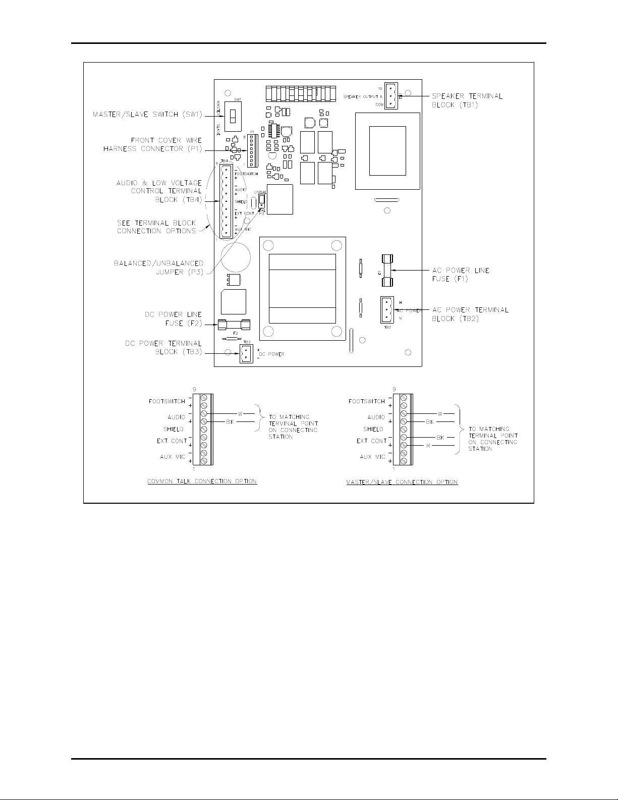
Figure 4. RigCom Station PCBA
f:\standard ioms - current release\42004 instr. man uals\42004-460a.doc
09/12
Page 7

Pub. 42004-460A
Model 400-003 IEC/ATEX Zone 1 RigCom Station Page: 7 of 16
System Line Balance
Each system requires termination of the audio pair wires with the 1 k/1-watt resistor (included with each
unit). The line balance resistor assembly is easily installed into the customer-supplied junction box.
OTE: Only one line balance resistor assembly is needed per system.
N
For cable runs that are approximately 1219 m (4,000 feet) or longer, it is recommended that the resistor
assembly be installed in a junction box (customer supplied) that is close to the center of the system. Refer
to Figure 5 and Figure 6. The junction box must be suitable for the applicable hazardous location in
which it is located.
Figure 5. System cable wiring less than 1219 m/4,000 feet in length
Figure 6. Master/Slave System cable wiring greater than 1219 m/4,000 feet in length
f:\standard ioms - current release\42004 instr. man uals\42004-460a.doc
09/12
Page 8

Pub. 42004-460A
Model 400-003 IEC/ATEX Zone 1 RigCom Station Page: 8 of 16
System Wiring
The maximum line length for the complete system, while still maintaining maximum output signal, is
4.5 km/15,000 feet for a system with less than ten stations using 1 mm
2
wiring, with stations spaced
equidistantly, and one station in the talk mode at a time. For each station in talk mode, the signal level
reduces by half. For systems with more than ten stations refer to Figure 7 for the maximum line distance.
Number of St ation per Line Length
5.00
4.50
4.00
3.50
3.00
wire (km)
2
2.50
2.00
Line Length 1mm
1.50
1.00
0.50
0.00
0 5 10 15 20 25 30
Number of Stations
Figure 7. Number of Stations vs. Line Length
f:\standard ioms - current release\42004 instr. man uals\42004-460a.doc
09/12
Page 9

Pub. 42004-460A
Model 400-003 IEC/ATEX Zone 1 RigCom Station Page: 9 of 16
Field Installation Interface
TB1 - Speaker Terminal Block
The following is a list of connections for the speaker output terminal block, TB1:
Name Pin No. Description
16 1 16-ohm terminal for speaker connection.
8 2 8-ohm terminal for speaker connection.
COM 3 Common terminal for speaker connection.
TB2 - AC Voltage Terminal Block
The following is a list of connections for the ac voltage terminal block, TB2:
Name Pin No. Description
AC Power H 1 Live/hot terminal of the external ac power supply. No connection when
external ac power supply is not used.
AC Power N 3 Neutral terminal of the external ac power supply. No connection when
external ac power supply is not used.
AC Power GND Ground/earth terminal for the ac power must be electrically connected to
the chassis.
TB3 - DC Voltage Terminal Block
The following is a list of connections for the dc voltage terminal block, TB3:
Name Pin No. Description
DC Power Input+ 2 Positive terminal of the external dc power supply. No connection when
external dc power supply is not used.
DC Power Input− 1 Negative terminal of the external dc power supply. No connection when
external dc power supply is not used.
NOTE: Either 120 V ac power or 12 V dc may be connected to the Model 400003 RigCom. Under no circumstances should ac and dc power be connected
to the 400-003.
f:\standard ioms - current release\42004 instr. man uals\42004-460a.doc
09/12
Page 10

Pub. 42004-460A
Model 400-003 IEC/ATEX Zone 1 RigCom Station Page: 10 of 16
TB4 - Audio and Low Voltage Control Terminal Block
The following is a list of connections for the low voltage control and audio signal terminal block, TB4:
Name Pin No. Description
Aux Mic+ 1 Positive terminal for auxiliary microphone (optional).
Aux Mic− 2 Negative terminal for auxiliary microphone (optional).
Ext Cont+ 3 Talk/listen control signal for Master/Slave operation.
No connection in Common Line mode.
Ext Cont− 4 Ground reference for talk/listen control signal for Master/Slave operation.
No connection in Common Line mode or UNBAL audio configuration.
Shield 5 Ground reference for shield terminations.
Audio+ 6 Positive of the audio line during 600-ohm or 15-kilohm termination
configuration.
Audio− 7 Negative of the audio page line during 600-ohm or 15-kilohm termination
configuration.
Footswitch+ 8 Positive of optional auxiliary footswitch operating as local push-to-talk switch.
Footswitch− 9 Negative of optional auxiliary footswitch that operating as local push-to-talk
switch.
P1 - Front Cover Wire Harness Connections
Plug in the front cover wire harness connector at P1. Refer to Figure 8.
f:\standard ioms - current release\42004 instr. man uals\42004-460a.doc
09/12
Figure 8.
Page 11

Pub. 42004-460A
Model 400-003 IEC/ATEX Zone 1 RigCom Station Page: 11 of 16
P3 - Balanced / Unbalanced Jumper
Jumper P3 allows the installer to configure the unit for balanced or unbalanced audio connections. If the
header is installed in the BAL position, the assembly is configured for a balanced audio input signal
operation. If the header is installed in the UNBAL position, the assembly is configured for an unbalanced
input signal. In systems where the external control signal is single-ended, the system must be set up as an
unbalanced system.
SW1 - Master/Slave Switch
Switch SW1 allows the installer to configure the unit as a Slave or Master unit. If the switch is in the
SLAVE position, the unit is configured as a Slave. If the switch is in the MASTER position, the unit is
configured as a Master. For Common Line operation, the switch must be in the MASTER position.
Figure 9. RigCom Station PCBA
f:\standard ioms - current release\42004 instr. man uals\42004-460a.doc
09/12
Page 12

Pub. 42004-460A
Model 400-003 IEC/ATEX Zone 1 RigCom Station Page: 12 of 16
Operation
The operator has access to an on-off/volume control switch and the push-to-talk push button.
The on-off/volume control switch allows the operator to turn the unit on or off and adjust the volume
level in the listen mode.
Turn the unit off by turning the switch completely anti/counterclockwise. For maximum volume adjust
the switch completely clockwise.
The push-to-talk push button controls the audio communication between stations.
When activated, the push-to-talk switch allows the operator to send a message to another station. When
not activated, the station is listen mode and the station receives messages from other stations. When a
station is configured as a Slave station, the push-to-talk switch has no function.
Common Line System
In the Common Line configuration, all of the stations are on common talking path and are normally in the
listen mode. When one of the stations has its push-to-talk toggle switch activated, its audio signal is
supplied to the audio lines. All other units receive the audio signal and broadcast the announcement over
their speakers. The push-to-talk switch must be held down as long as the operator talks. Releasing the
switch deactivates the microphone and returns the unit to the listen mode.
Figure 10. Common Talk Wiring Detail
f:\standard ioms - current release\42004 instr. man uals\42004-460a.doc
09/12
Page 13

Pub. 42004-460A
Model 400-003 IEC/ATEX Zone 1 RigCom Station Page: 13 of 16
Master/Slav e System
In the Master/Slave configuration, a Master station controls the talk-listen function of the Slave units
through external control wiring.
When the Master’s push-to-talk is not activated, the Slave stations are in talk mode allowing the Master to
monitor the Slave’s audio. When the Master’s push-to-talk is activated, the Slaves are in listen mode
allowing the Master to transmit audio to the Slave stations. The Slave’s push-to-talk is not operable, and
their operation is hands-free.
Figure 11. Master/Slave Wiring Detail
f:\standard ioms - current release\42004 instr. man uals\42004-460a.doc
09/12
Page 14

Pub. 42004-460A
Model 400-003 IEC/ATEX Zone 1 RigCom Station Page: 14 of 16
Maintenance
CAUTION
To reduce risk of electric shock, do not perform any servicing other than that contained in the
operating section unless you are qualified to do so.
Regular inspection and a good preventive maintenance program will increase the reliability of your
GAI-Tronics station. The GAI-Tronics Field Service Department can formulate a service contract suited
to your facility’s specific need for preventive maintenance.
WARNING
all power from the station.
CAUTION
To reduce the risk of ignition of hazardous atmospheres, disconnect the equipment from the supply
circuit before making any adjustments to the PCBA’s settings.
F1/F2 Fuses
WARNING
and size fuse for continued safe operation.
F1 is the fuse on the ac power line: 0.5 A, slow-blow type, 250 V, 520 mm, UL; or T400 mA, 250 V,
520 mm, IEC 60127-2/3.
These servicing instructions are for use by qualified service personnel only.
Before performing any of the following preventive maintenance steps, remove
Do not remove fuses when energized. Replace with the same type
F2 is the fuse on the dc power line: 2.0 A, slow-blow type, 250 V, 520 mm, UL; or T1.6 A, 250 V,
5 20 mm, IEC 60127-2/3.
Inspect and clean the machined flange flame joint surfaces of both the cover and box. Surfaces must be
smooth, free of nicks, scratches, dirt or any foreign particle build-up that would prevent a proper seal.
Surfaces must seat fully against each other to provide a proper explosion-proof joint. Clean surfaces by
wiping with a clean lint-free cloth.
Install and tighten all cover bolts to 17 ft-lbs. (23 N-m). Make certain no cover bolts are omitted. Use
only those bolts supplied with the enclosure.
Troubleshooting
Problem Solution
Problem with station
performance
Speaker volume too low. Adjust volume control.
Crosstalk One or more system cable pairs may be improperly terminated.
Review installation, ensuring that you correctly followed all
steps. Check all terminations on the board.
Replace speaker.
Visually inspect the system cable for accidental crossing of
cable pairs or grounds.
f:\standard ioms - current release\42004 instr. man uals\42004-460a.doc
09/12
Page 15

Pub. 42004-460A
Model 400-003 IEC/ATEX Zone 1 RigCom Station Page: 15 of 16
Specification s
AC Power
Voltage ............................................................................................................................ 120 V ac, 50/60 Hz
Power consumed (at nominal)
Off (mute) .......................................................................................................................... 6 VA, 1.8 W
Standby ............................................................................................................................ 7.2 VA, 3.6 W
Maximum speaker out ...................................................................................................... 30 VA, 27 W
DC Power
Voltage ................................................................................................................................................ 12 V dc
Power consumed (at nominal)
Off (mute) .................................................................................................................................... 0.3 W
Standby ............................................................................................................................................ 3 W
Maximum speaker out .................................................................................................................. 20 W
Amplifier PCBA
Frequency response ....................................................................................................... 300–8 kHz, +/−3 dB
Audio output ........................................................................................................................................ 8.0 W
Audio THD distortion ......................................................................................... 1% maximum, 8-W output
Hum/Noise .......................................................................................................... 1% maximum, 8-W output
Gain - Listen mode ................................................................................................................................ 30 dB
Gain - Talk mode (speaker as the microphone) .................................................................................... 42 dB
Gain - Talk mode (auxiliary microphone) ............................................................................................ 48 dB
Station
Construction/finish ....................................................................................... Cast aluminum/Tumblast finish
Mounting .................................................................. Wall or column, four 11-mm mounting feet with slots
Connections...................................................................................................... Plug-in style terminal blocks
Conduit entries ................................................................................. Bottom – three M20 1.5 tapped holes
Dimensions ........................................... 508.0 H 261.9 W 360.9 D mm (20.00 10.31 14.21 inches)
Shipping weight ................................................................................................................. 23.0 lbs. (10.5 kg)
Environmental
Temperature range (operating and storage) ......................................... −40º C to +60º C (−40º F to +140º F)
Humidity ...................................................................................................................... 95% non-condensing
Outdoor environmental rating .................................................................................................................. IP66
f:\standard ioms - current release\42004 instr. man uals\42004-460a.doc
09/12
Page 16

Pub. 42004-460A
Model 400-003 IEC/ATEX Zone 1 RigCom Station Page: 16 of 16
Approvals
CE Mark
Certificate No.
Notified Body Id No. 0539
Lyskear 8
DK-2730 Herlev
Denmark
DEMKO 12 ATEX 1116051 (ATEX) ..................................................................... II 2 GD Ex d IIB T6 Gb
II 2 D Ex tb IIIC T85 ºC Db IP66
IECEx UL 12.0012 (IECEx) ................................................................................................. Ex d IIB T6 Gb
Ex tb IIIC T85 ºC Db IP66
Replacement Parts
Contact GAI-Tronics for replacement part information.
Accessories
Part No. Description
12801-001 Auxiliary Microphone
51052-003 Auxiliary Footswitch
10438-101 Microphone I.S. Barrier Kit (contains 12801-001 Auxiliary Mic assembly)
60075-001 Audio cable, No. 18 AWG, (two-pair)
f:\standard ioms - current release\42004 instr. man uals\42004-460a.doc
09/12
Page 17

Warranty
Equipment. GAI-Tronics warrants for a period of one (1) year from the date of shipment, that any
GAI-Tronics equipment supplied hereunder shall be free of defects in material and workmanship, shall
comply with the then-current product specifications and product literature, and if applicable, shall be fit
for the purpose specified in the agreed upon quotation or proposal document. If (a) Seller’s goods prove
to be defective in workmanship and/or material under normal and proper usage, or unfit for the purpose
specified and agreed upon, and (b) Buyer’s claim is made within the warranty period set forth above,
Buyer may return such goods to GAI-Tronics nearest depot repair facility, freight prepaid, at which time
they will be repaired or replaced, at Seller’s option, without charge to Buyer. Repair or replacement shall
be Buyer’s sole and exclusive remedy. The warranty period on any repaired or replacement equipment
shall be the greater of the ninety (90) day repair warranty or one (1) year from the date the original
equipment was shipped. In no event shall GAI-Tronics warranty obligations with respect to equipment
exceed 100% of the total cost of the equipment supplied hereunder. Buyer may also be entitled to the
manufacturer’s warranty on any third-party goods supplied by GAI-Tronics hereunder. The applicability
of any such third-party warranty will be determined by GAI-Tronics.
Services. Any services GAI-Tronics provides hereunder, whether directly or through subcontractors,
shall be performed in accordance with the standard of care with which such services are normally
provided in the industry. If the services fail to meet the applicable industry standard, GAI-Tronics will reperform such services at no cost to buyer to correct said deficiency to Company's satisfaction provided
any and all issues are identified prior to the demobilization of the Contractor's personnel from the work
site. Re-performance of services shall be Buyer's sole and exclusive remedy, and in no event shall GAITronics warranty obligations with respect to services exceed 100% of the total cost of the services
provided hereunder.
Warranty Periods. Every claim by Buyer alleging a defect in the goods and/or services provided
hereunder shall be deemed waived unless such claim is made in writing within the applicable warranty
periods as set forth above. Provided, however, that if the defect complained of is latent and not
discoverable within the above warranty periods, every claim arising on account of such latent defect shall
be deemed waived unless it is made in writing within a reasonable time after such latent defect is or
should have been discovered by Buyer.
Limitations / Exclusions. The warranties herein shall not apply to, and GAI-Tronics shall not be
responsible for, any damage to the goods or failure of the services supplied hereunder, to the extent
caused by Buyer’s neglect, failure to follow operational and maintenance procedures provided with the
equipment, or the use of technicians not specifically authorized by GAI-Tronics to maintain or service the
equipment. THE WARRANTIES AND REMEDIES CONTAINED HEREIN ARE IN LIEU OF AND
EXCLUDE ALL OTHER WARRANTIES AND REMEDIES, WHETHER EXPRESS OR IMPLIED BY
OPERATION OF LAW OR OTHERWISE, INCLUDING ANY WARRANTIES OF
MERCHANTABILITY OR FITNESS FOR A PARTICULAR PURPOSE.
Return Policy
If the equipment requires service, contact your Regional Service Center for a return authorization number
(RA#). Equipment should be shipped prepaid to GAI-Tronics with a return authorization number and a
purchase order number. If the equipment is under warranty, repairs or a replacement will be made in
accordance with the warranty policy set forth above. Please include a written explanation of all defects to
assist our technicians in their troubleshooting efforts.
Call 800-492-1212 (inside the USA) or 610-777-1374 (outside the USA) for help identifying the
Regional Service Center closest to you.
(Rev. 10/06)
 Loading...