

Page 1

Pub. 42004-714L2C
GAI-TRONICS® CORPORATION
A HUBBELL COMPANY
Model 379-001
Monitored Relay Module (MRM) Station
Confidential ity Notice
This manual is provided solely as an operational, installation, and maintenance guide and contains
sensitive business and technical information that is confidential and proprietary to GAI-Tronics.
GAI-Tronics retains all intellectual property and other rights in or to the information contained herein,
and such information may only be used in connection with the operation of your GAI-Tronics product or
system. This manual may not be disclosed in any form, in whole or in part, directly or indirectly, to any
third party.
General Information
The Model 379-001 Monitored Relay Module (MRM) Station is used in SmartSeries ADVANCE
Systems. Operation is controlled by the system’s Master Control Unit (MCU) programming.
The MRM provides eight relay output circuits. Each relay contains two type “C” contacts rated for 5A.
Relay outputs are typically used for switching power to signaling devices such as beacons or strobes but
can be used for any switching application that does not exceed the relay’s current rating. Relay circuits
can be programmed to activate during system alarms, pages, or trouble condition.
The MRM also contains eight input circuits. Input circuits can be used supervise the cable integrity
connecting the relay output to the signaling device (as described above). During an inactive state, the
cable is monitored for open circuit, short circuit and ground fault conditions. If a cable fault is detected,
the relay circuit will not activate, preventing a possible dangerous condition. The fault condition is
automatically reported to the MCU.
For each relay circuit not requiring supervision, one input circuit is available for other functions. Inputs
are activated by a voltage-free contact (either opening or closing) or the presence/absence of a 24 V dc
input voltage. When using inputs from voltage-free contacts, the MRM can supervise the cabling
between the input terminal and the remote contact closure device. The cable is monitored for open
circuit, short circuit and ground fault conditions. The fault condition is automatically reported to the
MCU.
Each input circuit can be programmed to initiate one of the following functions in the ADVANCE
System.
• Activate an alarm
• Reset all alarms
• Cancel the current alarm
• Report a fault condition
• Reset the system MCU
GAI-Tronics Corporation 400 E. Wyomissing Ave. Mohnton, PA 19540 USA
610-777-1374 800-492-1212 Fax: 610-796-5954
V
ISIT WWW.GAI-TRONICS.COM FOR PRODUCT LITERATURE AND MANUALS
Page 2
Pub. 42004-714L2C
Model 379-001 Monitored Relay Module Station Page: 2 of 9
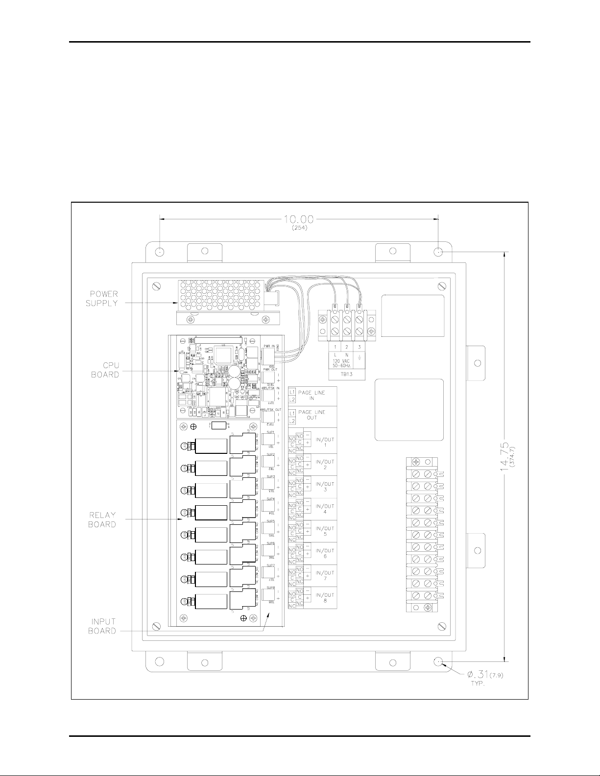
The Model 379-001 Monitored Relay Module (MRM) Station components are housed in a NEMA 4X
stainless steel enclosure measuring 13.0 W × 14.3 H × 6.23 D inches. Components include a 12 V dc
power supply, a 12579-003 Monitored Relay Module, and two terminal blocks.
The 12579-003 Monitored Relay Module is comprised of three components: the 69613-001TR CPU and
the 69251-201TR Monitored-Input PCBA, and the 69252-001TR Relay PCBA. Refer to Figure 1 for
component locations.
The scope of this manual is limited to the mounting and wiring connections for the Model 379-001
Station. Refer to Pub. 42004-716L2 for additional information on the 12579-003 Monitored Relay
Module.
Figure 1. Model 379-001 MRM Station (Interior View)
f:\standard ioms - current release\42004 instr. manuals\42004-714l2c.doc
08/11
Page 3
Pub. 42004-714L2C
Model 379-001 Monitored Relay Module Station Page: 3 of 9
Installation
CAUTION
Do not install this equipment in hazardous areas other than those indicated on the approval listing
in the “Specifications” section of this manual. Such installation may cause a safety hazard and
consequent injury or property damage. Disconnect power before installing or removing the MRM.
Mounting
The Model 379-001 MRM Station enclosure is not supplied with conduit or cable gland holes since cable
quantity, size, and entry location vary with each installation.
Drill or punch openings at the required locations before mounting the enclosure. Typically multiple
cables entries are required for SmartSeries Page/Party
®
system cable and input wiring. Refer to the
Wiring section below. Use caution when drilling or punching the enclosure to avoid damaging the
internal components. Bottom cable entry is recommended to prevent moisture from entering the
enclosure and dripping onto the terminals or circuit boards.
Mount the enclosure to a suitable surface using appropriate customer-supplied hardware. Refer to Figure
1 for mounting hole dimensions.
Remove the shipping tie-wrap that is securing the PCBA to its mounting Snaptrack.
Wiring
The MRM Station is parallel-wired to the Page/Party® system cable in the same fashion as SmartSeries
handset/speaker stations. The system cable distributes ac power, party line audio and page line to the
stations. The MRM requires only ac power and page line connections from the system cable. Spare
terminals are provided for the unused conductors in the system cable. A separate cable(s) is generally
used for the input connections. Each connection is explained below.
Power
120 V ac power is connected to terminal block TB13 at the top of the panel. Refer to Figure 1. AC
power is accessed from the Page/Party
Function Terminal Block System Cable Wire Color
®
system cable per the following table.
AC Line (hot) TB13-1 Black
Neutral TB13-2 White
Ground TB13-3 Green/yellow
f:\standard ioms - current release\42004 instr. manuals\42004-714l2c.doc
08/11
Page 4

Pub. 42004-714L2C
Model 379-001 Monitored Relay Module Station Page: 4 of 9
Page Line
The page line twisted pair in the Page/Party
®
system cable serves as the data line between the MRM and
the ADVANCE System Control Cabinet. The page line connections are made to the MRM module per
the following table. Refer to Figure 1 for terminal locations.
Function MIM Terminal B lock System Cable Wire Color
Page Line (L1) TB 11 (L1) Red/blue
Page Line (L2) TB 11 (L2) Blue/red
Inputs
Input connections (from voltage-free contacts or switched 24 V dc voltage sources) are made to screw
terminals TB1 through TB8 on the input PCBA. Refer to Figure 1 for terminal locations.
To ensure proper termination, ferrules should be crimped on the end of all input wires prior to
connecting the MRM terminal blocks. The terminal blocks may accept No. 28–2 AWG
conductors.
Each input is wired to operate in one of five input configurations (modes) that is set via system
programming. Each mode requires a unique connection scheme between the external field device and the
corresponding input terminals on the MRM. The connection scheme for each input mode is described
below. Since the each input operates independently, only input 1 will be discussed. Inputs 2–8 are
identical.
Mode 0: Deactivate Circuit
The input circuit is disabled via system programming. No external connections may be made to
connector TB1.
Mode 1: IDC Line Super vision (Multiple Switches)
In this mode, any number of normally open voltage-free contact closures may be installed on the input
line and a 20 kΩ resistor must be installed across the last contact. The cable is monitored for ground
faults and open circuits. When the contacts are inactive (open), the line appears as 20 kΩ load. This
indicates a healthy inactive cable loop.
Figure 2. Multiple normally-open switches
When any contact is closed, the 20 kΩ resistor is bypassed. The input circuit is shorted, indicating an
active input.
f:\standard ioms - current release\42004 instr. manuals\42004-714l2c.doc
08/11
Page 5

Pub. 42004-714L2C
Model 379-001 Monitored Relay Module Station Page: 5 of 9
If either cable leg is grounded, or if a cable break occurs on either leg, the 20 kΩ load is removed
indicating a fault condition.
OTE: The 20 kΩ, 5% tolerance resistor is not included with the MRM. This resistor is included in the
N
Model 12509-003 Kit, which is sold separately.
Mode 2: IDC Single Normally-Open (N.O.) Switch
In this configuration, only one normally open voltage-free contact closure may be installed and a 5.1 kΩ
and 15 kΩ resistor must be wired in series/parallel with the contact. The cable is monitored for open
circuits, wire-to-wire short circuits (across + and −), and ground faults. When the contact is inactive
(open), the line appears as 20.1 kΩ load (15 kΩ in series with 5.1 kΩ). This indicates a healthy inactive
cable loop.
Figure 3. Single normally-open switch
When the contact closed, the 15 kΩ resistor is bypassed. The circuit then sees only the 5.1 kΩ load,
indicating an active input.
If there is a short across + and −, if either cable leg is grounded, or if a cable break occurs on either leg,
the 20 kΩ load is removed indicating a fault condition.
OTE: The terminating resistors are not included with the MRM. These resistors are included in the
N
Model 12509-003 Kit, which is sold separately.
f:\standard ioms - current release\42004 instr. manuals\42004-714l2c.doc
08/11
Page 6

Pub. 42004-714L2C
Model 379-001 Monitored Relay Module Station Page: 6 of 9
Mode 3: IDC Single Normally-Closed (N.C.) Switch
In this configuration, only one normally closed voltage-free contact may be installed and a 5.1 kΩ and 15
kΩ resistor must be wired in series/parallel with the contact. The cable is monitored for open circuits,
wire-to-wire short circuits (across + and −), and ground faults. When the contact is closed, the 15 kΩ is
bypassed and the circuit sees only the 5.1 kΩ load. This indicates a healthy inactive cable loop.
Figure 4. Single normally-closed switch
When the contact opens, the circuit then sees 20.1 kΩ load (15 kΩ in series with 5.1 kΩ), indicating an
active input.
If there is a short across + and −, if either cable leg is grounded, or if a cable break occurs on either leg,
the 20.1 kΩ load is removed indicating a fault condition.
OTE: The terminating resistors are not included with the MRM. These resistors are included in the
N
Model 12509-003 Kit, which is sold separately.
Mode 4: IAC Line Super vision
In this mode, multiple strobe lights may be installed across the common relay terminals. Total strobe
current draw cannot exceed 5A. A 20 kΩ 2W resistor must be installed across the last strobe. The strobe
power source is connected to the normally open relay terminals. The normally closed relay terminals are
connected to the corresponding input terminals. (Relay 1 to Input 1, Relay 2 to Input 2, etc.) Refer to
Figure 5 and Figure 6 below.
During an inactive condition, the input circuit monitors the strobe cable for open circuits, short circuits
and ground faults. Under normal conditions the line appears as 20 kΩ load, indicating a healthy cable
loop.
During an active condition, the relay contacts change state. The input circuit is isolated from the strobe
cable and power is applied to activate the strobes. The cable loop is not monitored during active relay
conditions.
f:\standard ioms - current release\42004 instr. manuals\42004-714l2c.doc
08/11
Page 7

Pub. 42004-714L2C
Model 379-001 Monitored Relay Module Station Page: 7 of 9
Figure 5. Cable supervision for ac-powered strobes
Figure 6. Cable supervision for dc-powered strobes
f:\standard ioms - current release\42004 instr. manuals\42004-714l2c.doc
08/11
Page 8

Pub. 42004-714L2C
Model 379-001 Monitored Relay Module Station Page: 8 of 9
Mode 5: IDC Non-Supervision Multiple Switch (Voltage-free Contact)
In this mode, any number of normally open dry contact closures can be installed on the line. No end-ofline resistors are installed. The cable loop is not
monitored for any faults.
Figure 7. Non-Supervision Multiple Switches
When the contact is open the circuit is inactive, and when the contact is closed, the circuit is active.
Mode 5: IDC Non-Supervision (24 V DC)
In this mode, a 24 V dc voltage source can be installed on the line. No end-of-line resistors are installed.
The cable loop is not
monitored for any faults.
Shorting jumpers (located next to the input terminals) must be moved from the factory default of “dry” to
“wet” contact mode.
When set to “wet” contact mode, the input can be activated during a 0 V condition or a 24 V condition
depending on the “active” jumper position. The factory default setting is “24 V dc input when active”
(position 2-3). If “0 V dc input when active” is desired, move jumper from position 2-3 to position 1-2.
Ensure the polarity of input connection is correct as it is polarity sensitive.
Figure 8. Non-Supervision (wet contact)
f:\standard ioms - current release\42004 instr. manuals\42004-714l2c.doc
08/11
Page 9

Pub. 42004-714L2C
Model 379-001 Monitored Relay Module Station Page: 9 of 9
Relay Ou tputs
Field wiring connections are made to the screw terminals on the relay PCBA. Eight relays are available;
each contains two type “C” contacts rated for 5A. The normally open (NO), common (C), and normally
closed (NC) terminals are labeled on the relay PCBA. Refer to Figure 1 for terminal locations. Refer to
Figure 5 for a typical beacon light connection diagram.
To ensure proper termination, ferrules should be crimped on the end of all input wires prior to
connecting the relay terminal blocks. The terminal blocks can accept No. 28–12 AWG
conductors.
Setting the Station Address
Each station connected to the Page/Party® system cable requires a unique address. Valid address settings
are hexadecimal numbers 05 through FE. The address for each station is determined by the system
programming.
Two hexadecimal switches located on the MIM CPU Board set the station address. The address consists
of a low address setting and high address setting. Each switch contains 16 settings, labeled 0–F. The
MRM station’s address is determined by the high address setting followed by the low address setting.
For example, to assign an address of 05, the high address is set to 0 and the low address is set to 5.
Specification s
Electrical
Power requirements ............................................................................ 120 V ac, 50/60 Hz @ 1A maximum
N
OTE: Power requirements do NOT include power switched to external devices such as strobe lights.
Mechanical
Enclosure material ..................................................................................... No. 16 gauge, 316 stainless steel
Dimensions ............................................................................................... 13.0 W × 14.3 H × 6.23 D inches
Weight.................................................................................................................................................. 19 lbs.
Environmental
Humidity .......................................................................................... 95% non-condensing relative humidity
Temperature range .................................................................................. −22º F to 158º F (−30º C to 70º C)
Environmental rating .................................................................................................................... NEMA 4X
Replac ement Parts
Part Number Description
69613-001TR PCBA, CPU Module with FSK
69251-201TR PCBA, Monitored-In-8
69252-001TR PCBA, Relay Module
40404-009 Power Supply, 12 V dc, 25W
f:\standard ioms - current release\42004 instr. manuals\42004-714l2c.doc
08/11
Page 10

Warranty
Equipment. GAI-Tronics warrants for a period of one (1) year from the date of shipment, that any
GAI-Tronics equipment supplied hereunder shall be free of defects in material and workmanship, shall
comply with the then-current product specifications and product literature, and if applicable, shall be fit
for the purpose specified in the agreed-upon quotation or proposal document. If (a) Seller’s goods prove
to be defective in workmanship and/or material under normal and proper usage, or unfit for the purpose
specified and agreed upon, and (b) Buyer’s claim is made within the warranty period set forth above,
Buyer may return such goods to GAI-Tronics’ nearest depot repair facility, freight prepaid, at which time
they will be repaired or replaced, at Seller’s option, without charge to Buyer. Repair or replacement shall
be Buyer’s sole and exclusive remedy. The warranty period on any repaired or replacement equipment
shall be the greater of the ninety (90) day repair warranty or one (1) year from the date the original
equipment was shipped. In no event shall GAI-Tronics warranty obligations with respect to equipment
exceed 100% of the total cost of the equipment supplied hereunder. Buyer may also be entitled to the
manufacturer’s warranty on any third-party goods supplied by GAI-Tronics hereunder. The applicability
of any such third-party warranty will be determined by GAI-Tronics.
Services. Any services GAI-Tronics provides hereunder, whether directly or through subcontractors,
shall be performed in accordance with the standard of care with which such services are normally
provided in the industry. If the services fail to meet the applicable industry standard, GAI-Tronics will
re-perform such services at no cost to buyer to correct said deficiency to Company's satisfaction provided
any and all issues are identified prior to the demobilization of the Contractor’s personnel from the work
site. Re-performance of services shall be Buyer’s sole and exclusive remedy, and in no event shall GAITronics warranty obligations with respect to services exceed 100% of the total cost of the services
provided hereunder.
Warranty Periods. Every claim by Buyer alleging a defect in the goods and/or services provided
hereunder shall be deemed waived unless such claim is made in writing within the applicable warranty
periods as set forth above. Provided, however, that if the defect complained of is latent and not
discoverable within the above warranty periods, every claim arising on account of such latent defect shall
be deemed waived unless it is made in writing within a reasonable time after such latent defect is or
should have been discovered by Buyer.
Limitations / Exclusions. The warranties herein shall not apply to, and GAI-Tronics shall not be
responsible for, any damage to the goods or failure of the services supplied hereunder, to the extent
caused by Buyer’s neglect, failure to follow operational and maintenance procedures provided with the
equipment, or the use of technicians not specifically authorized by GAI-Tronics to maintain or service the
equipment. THE WARRANTIES AND REMEDIES CONTAINED HEREIN ARE IN LIEU OF AND
EXCLUDE ALL OTHER WARRANTIES AND REMEDIES, WHETHER EXPRESS OR IMPLIED BY
OPERATION OF LAW OR OTHERWISE, INCLUDING ANY WARRANTIES OF
MERCHANTABILITY OR FITNESS FOR A PARTICULAR PURPOSE.
Return Policy
If the equipment requires service, contact your Regional Service Center for a return authorization number
(RA#). Equipment should be shipped prepaid to GAI-Tronics with a return authorization number and a
purchase order number. If the equipment is under warranty, repairs or a replacement will be made in
accordance with the warranty policy set forth above. Please include a written explanation of all defects to
assist our technicians in their troubleshooting efforts.
Call 800-492-1212 (inside the USA) or 610-777-1374 (outside the USA) for help identifying the
Regional Service Center closest to you.
(Rev. 10/06)
 Loading...