

Page 1

Pub. 42004-525A
GAI-TRONICS®
A H U B B E L L C O M P A N Y
Model 370-901 SP2 to Page/Party® Bridge
T A B L E O F C O N T E N T S
Confidentiality Notice .....................................................................................................................1
General Information .......................................................................................................................1
Features .................................................................................................................................................... 1
Option ...................................................................................................................................................... 1
Installation ......................................................................................................................................2
Important Safety Instructions................................................................................................................ 2
Open the Enclosure ................................................................................................................................. 2
Mount the Enclosure ............................................................................................................................... 3
Field Terminations .................................................................................................................................. 3
Earth Ground ......................................................................................................................................... 3
Ethernet—TB1 ...................................................................................................................................... 4
Page/Party® 33-Ohm Audio Connections—P2 ..................................................................................... 5
60029 Series Page/Party® System Cable ............................................................................................... 5
Channel Isolation Inputs—P3 ............................................................................................................... 6
Contact Outputs—P4 ............................................................................................................................ 6
Mute Connection—P5 .......................................................................................................................... 7
Power—P1 ............................................................................................................................................ 7
Close the Enclosure ................................................................................................................................. 7
Configuration ..................................................................................................................................7
Interface Configuration .......................................................................................................................... 9
Channel Configuration ......................................................................................................................... 10
GUDA Status ......................................................................................................................................... 11
Interface Status .................................................................................................................................... 11
Channel and Redundant Channel Status ............................................................................................. 12
Operation .......................................................................................................................................12
Global Disable ....................................................................................................................................... 12
System Reset .......................................................................................................................................... 13
System Status LEDs .............................................................................................................................. 13
Ethernet Status LEDs ........................................................................................................................... 13
Maintenance ..................................................................................................................................13
GUDA Device Administrator Options ................................................................................................ 14
Save Configuration Locally .................................................................................................................. 14
Import Saved Configuration ................................................................................................................ 15
GAI-TRONICS 3030 KUTZTOWN RD. READING, PA 19605 USA
610-777-1374 800-492-1212 Fax: 610-796-5954
VISIT WWW.GAI-TRONICS.COM FOR PRODUCT LITERATURE AND MANUALS
Page 2

Table of Contents Pub. 42004-525A
GUDA Software Updates ..................................................................................................................... 15
Troubleshooting .................................................................................................................................... 15
Service and Spare Parts ........................................................................................................................ 16
Specifications ................................................................................................................................16
Electrical ................................................................................................................................................ 16
Ethernet ................................................................................................................................................. 16
Mechanical ............................................................................................................................................. 16
Environmental ....................................................................................................................................... 16
Audio ...................................................................................................................................................... 16
GAI-TRONICS 3030 KUTZTOWN RD. READING, PA 19605 USA
610-777-1374 800-492-1212 Fax: 610-796-5954
VISIT WWW.GAI-TRONICS.COM FOR PRODUCT LITERATURE AND MANUALS
Page 3
Pub. 42004-525A
GAI-TRONICS®
A HUBBELL COMPANY
Model 370-901 SP2 to Page/Party® Bridge
Confidential ity Notice
This manual is provided solely as an installation, operation, and maintenance guide and contains sensitive
business and technical information that is confidential and proprietary to GAI-TRONICS. GAITRONICS retains all intellectual property and other rights in or to the information contained herein, and
such information may only be used in connection with the operation of your GAI-TRONICS product or
system. This manual may not be disclosed in any form, in whole or in part, directly or indirectly, to any
third party.
General Information
The Model 370-901 SP2 to Page/Party® Bridge
interfaces GAI-TRONICS SP2 stations to existing
Page/Party
integrating completely into a Page/Party
Audio detection and isolate functionality ensures proper
operation of existing Page/Party
®
systems. The bridge is capable of
®
accessories.
®
or ICS system.
Fea tures
converts six 33-ohm audio lines to SP2 multicast
channels (one page line and five party lines)
indoor, wall-mount unit
six channel isolation inputs
configurable system isolation functionality
six contact outputs
Option
SP2 to Page/Party® Redundancy
Figure 1. SP2 to Page/Party® Bridge
GAI-TRONICS 3030 KUTZTOWN RD. READING, PA 19605 USA
610-777-1374 800-492-1212 Fax: 610-796-5954
ISIT WWW.GAI-TRONICS.COM FOR PRODUCT LITERATURE AND MANUALS
V
Page 4
Pub. 42004-525A
Model 370-901 SP2 to Page/Party
®
Bridge Page 2 of 16
Installation
Important Safety Instructions
Read, follow, and retain instructions—All safety and operating instructions should be read and
followed before operating the unit. Retain instructions for future reference.
Heed warnings—Adhere to all warnings on the unit and in the operating instructions.
Attachments—Attachments not recommended by the product manufacturer should not be used; as
they may cause hazards.
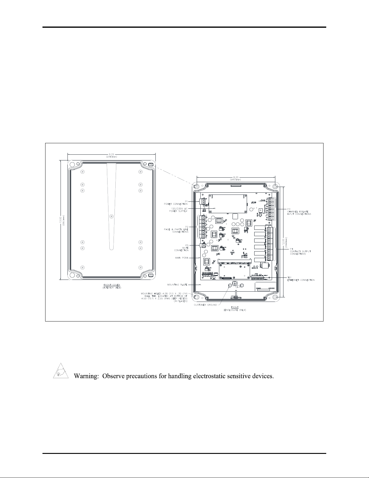
Open the Enclosure
®
Figure 2. Model 370-901 SP2 to Page/Party
Bridge
1. Remove and retain the four screws on the front cover.
2. Open the hinged front cover of the enclosure and turn it to the left.
3. Pull up on the left side of the enclosure front cover until the hinge pins pull loose.
4. Separate the front and rear sections.
5. Set the front cover of the enclosure and the four screws aside.
P:\Standard IOMs - Current Release\42004 Instr. Manuals\4 2004-525A.docx
08/18
Page 5
Pub. 42004-525A
Model 370-901 SP2 to Page/Party
®
Bridge Page 3 of 16
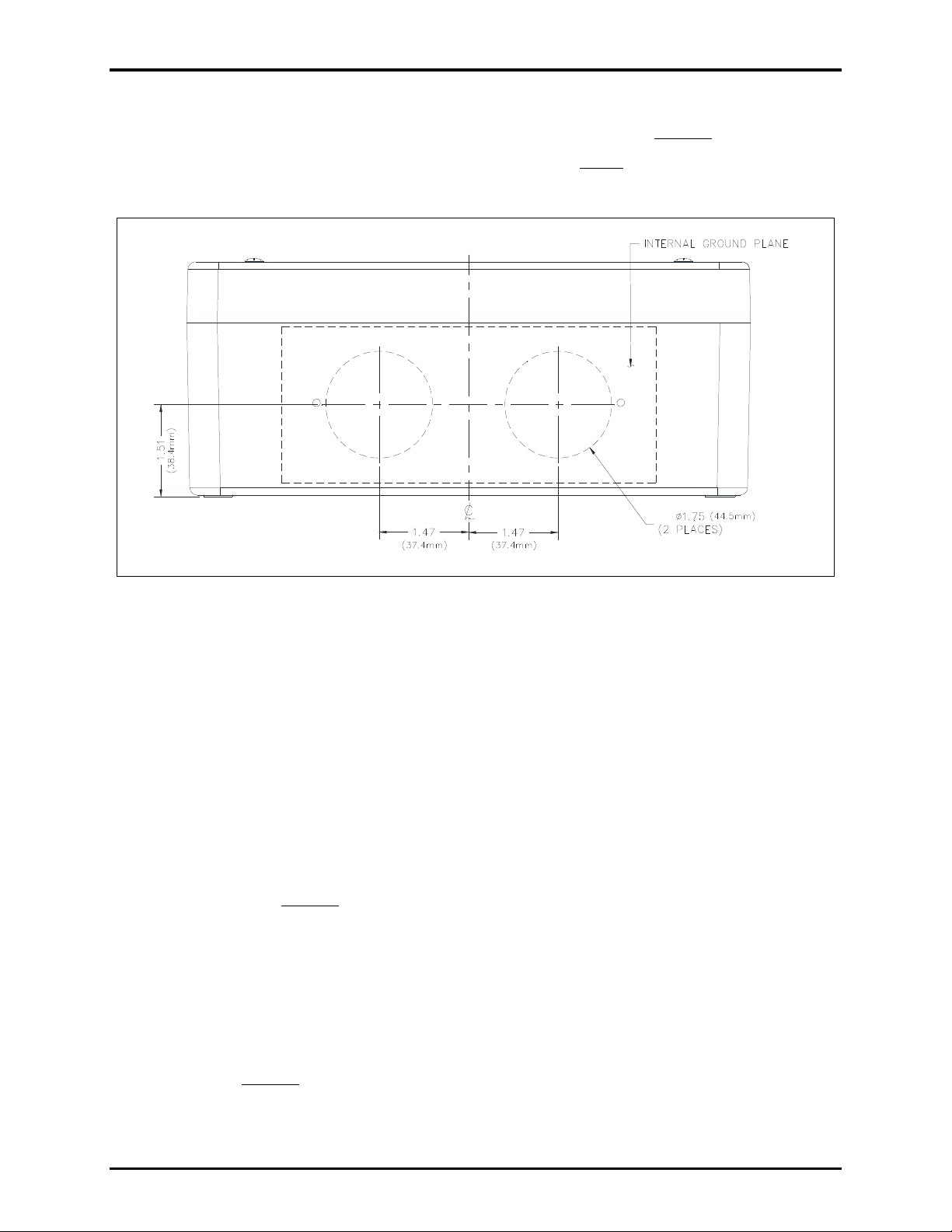
Mount the Enclosure
1. Determine the conduit or cable gland location(s) on the rear enclosure (see Figure 3).
NOTE: The drill spots provided on the outside of the enclosure do not line up with the center of the
holes that must be drilled in the enclosure to accept the conduit.
Figure 3. Ground Plate Hole Locations
2. Cut or punch the appropriate size hole(s) in the enclosure.
The ground plate accepts two conduits up to 1.75 inches in diameter.
3. Secure the rear enclosure to the wall with screws or appropriate fasteners.
The enclosure mounting holes are 0.280-inches in diameter.
™
4. Install conduit using Myers
ST-4 (1.25-inch) Scru-Tite® hubs or equivalent.
Reducers must be used for smaller conduit sizes to ensure proper contact with the supplied grounding
plates. Hub(s) must be connected to the conduit before being connected to the enclosure.
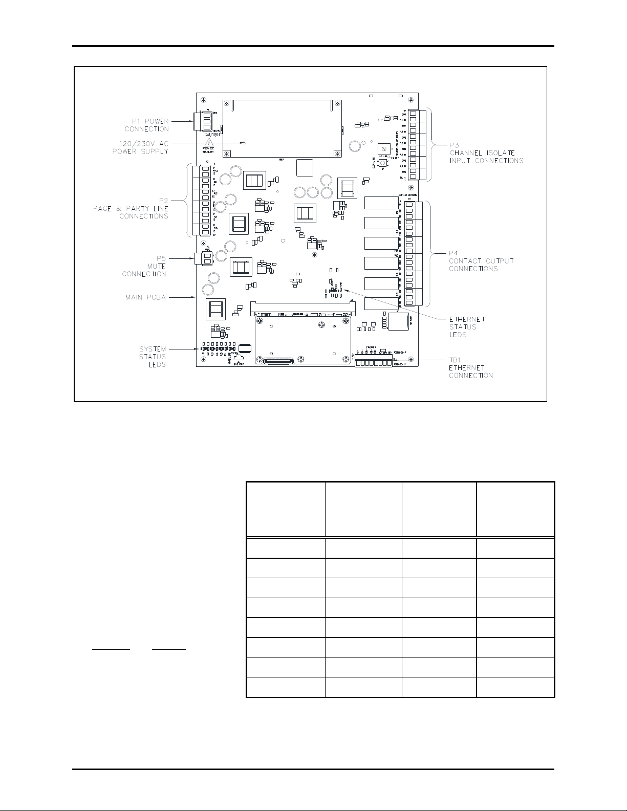
Field T erminations
The SP2 to Page/Party® Bridge provides terminal blocks on the main PCBA located in the rear of the
enclosure for field wiring the power, 33-ohm Page/Party
and contact outputs (see Figure 4)
Earth Ground
The bridge must be connected to earth ground.
1. Pull the power supply cable or a separate green/yellow sheathed ground cable into the enclosure.
®
audio lines, Ethernet, channel isolation inputs,
2. Install a #6 ring lug on the ground conductor.
3. Secure the ground conductor to the C
USTOMER GROUND lug located in the bottom of the rear
enclosure (see Figure 2).
P:\Standard IOMs - Current Release\42004 Instr. Manuals\4 2004-525A.docx
08/18
Page 6
Model 370-901 SP2 to Page/Party
®
Bridge Page 4 of 16
Pub. 42004-525A
Ethernet—TB1
Terminate the Ethernet connection
at terminal block TB1.
1. Pull a Category 5 or better
Ethernet cable through the
conduit and into the enclosure.
2. Install ferrules onto the wire
ends.
3. Connect the Ethernet cable to
the 8-position pluggable
terminal block TB1 (see
Figure 4 and Table 1).
4. Connect the pluggable
terminal block to terminal
block receptacle TB1.
Figure 4. Main PCBA
Table 1. Ethernet Connector Wiring—TB1
1000Base-
T Signal
(Label)
100Base-
TX Signal
(Label)
DA+ TX+
DA− TX−
DB+ RX+
DB− RX−
DC+
DC−
DD+
DD−
Wire
Color
Wire Color
Designator
Orange Stripe o
Solid Orange O
Green Stripe g
Solid Green G
Solid Blue B
Blue Stripe b
Brown Stripe br
Solid Brown BR
P:\Standard IOMs - Current Release\42004 Instr. Manuals\4 2004-525A.docx
08/18
Page 7

Pub. 42004-525A
16-Conductor Cable
(60029 Series)
16-Conductor Cable
(60029 Series)
Color Code
Function
Color Code
Function
Black
120 V ac Line
Tan/Violet
Party Line 2 (L2)
White
120 V ac Neutral
Blue
Party Line 3 (L1)
Green/Yellow
Ground
Tan/Blue
Party Line 3 (L2)
Red/Blue
Page Line (L1)
Brown
Party Line 4 (L1)
Blue/Red
Page Line (L2)
Tan/Brown
Party Line 4 (L2)
Red
Party Line 1 (L1)
Yellow
Party Line 5 (L1)
Tan/Red
Party Line 1 (L2)
Tan/Yellow
Party Line 5 (L2)
Violet
Party Line 2 (L1)
Orange
Spare
Table 2. Page and Party Line
33-Ohm Audio Connections—P2
Terminal
Label
Wire Size/Color
P2-1
PAGE
L1
See the 60029
Series System Cable
section below
P2-2
L2
P2-3
PL1
L1
P2-4
L2
P2-5
PL2
L1
P2-6
L2
P2-7
PL3
L1
P2-8
L2
P2-9
PL4
L1
P2-10
L2
P2-11
PL5
L1
P2-12
L2
PLn := Party Line 1..5
Model 370-901 SP2 to Page/Party® Bridge Page 5 of 16
Page/Party® 33-Ohm Audio Connections—P2
Terminal block P2 provides connections for
six, 33-ohm audio lines (typically one page
and five party lines). Connect the six
Page/Party® audio lines to the six, twoposition pluggable terminal blocks P2 as
follows:
1. Pull the Page/Party® system cable through
the conduit and into the enclosure.
2. Install ferrules onto the wire ends of each
page and party line audio pair.
3. Connect each audio pair to one of the
two-position terminal blocks (see Figure
4 and Table 2).
4. Connect the six P2 terminal blocks to the
terminal block receptacle P2 (see Figure
4).
60029 Series Page/Party® System Cable
Page/Party® stations should be connected using GAI-TRONICS 60029 Series system cable. Refer to
Table 3 for the Page/Party® system cable color codes:
Table 3. Page/Party® 60029 Series System Cable
P:\Standard IOMs - Current Release\42004 Instr. Manuals\42004-525A.docx
08/18
Page 8

Pub. 42004-525A
Table 4. Channel Isolation
Input Connections—P3
Channel
Isolated
Label
Description
Page Line
PG IN
Page In +
GND
Page In −
Party Line 1
PL1 IN
Party Line 1 +
GND
Party Line 1 −
Party Line 2
PL2 IN
Party Line 2 +
GND
Party Line 2 −
Party Line 3
PL3 IN
Party Line 3 +
GND
Party Line 3 −
Party Line 4
PL4 IN
Party Line 4 +
GND
Party Line 4 −
Party Line 5
PL5 IN
Party Line 5 +
GND
Party Line 5 −
Table 5. Contact Outputs—P4
Output
Label
Description
Page
Line
NC
normally closed page contact
COM
page output common
NO
normally open page contact
Party
Line 1
NC
normally closed PL1 contact
COM
PL1 output common
NO
normally open PL1 contact
Party
Line 2
NC
normally closed PL2 contact
COM
PL2 output common
NO
normally open PL2 contact
Party
Line 3
NC
normally closed PL3 contact
COM
PL3 output common
NO
normally open PL3 contact
Party
Line 4
NC
normally closed PL4 contact
COM
PL4 output common
NO
normally open PL4 contact
Party
Line 5
NC
normally closed PL5 contact
COM
PL5 output common
NO
normally open PL5 contact
PLn := Party Line 1..5
Model 370-901 SP2 to Page/Party® Bridge Page 6 of 16
Channel Isolation Inputs—P3
Channel isolation inputs independently isolate SP2
multicast channel audio from each of the six
Page/Party® audio lines. Activation of an input
disconnects the SP2 and Page/Party® audio signals in
the bridge for that audio channel. This prevents audio
from traversing the bridge to the receiving system.
Terminate the six channel isolation inputs to terminal
block P3 (see Figure 4). P3 is a 12-position terminal
block. Six, two-position terminal plugs are used; one
for each channel isolation input. Complete the
termination as follows:
1. Pull the cable(s) for the channel isolation inputs
through the conduit and into the enclosure.
2. Install ferrules onto the wire ends.
3. Connect each channel pair to the two-position
pluggable terminal block for that channel (see
Figure 4 and Table 4).
4. Plug the six two-position pluggable blocks into
terminal block P3.
Contact Outputs—P4
The SP2 to Page/Party® Bridge is equipped
with six contact outputs (see Figure 4).
Outputs become active when a digital audio
signal is detected on the associated SP2
audio channel. These outputs may then be
used to actuate field devices when SP2
page or party-lines go off-hook.
The outputs are terminated at terminal
block P4. P4 is an 18 position terminal
block. Three-position pluggable terminal
blocks are used for each output to simplify
the connection of the outputs:
1. Pull the cable(s) for the contact outputs
through the conduit and into the
enclosure.
2. Install ferrules onto the wire ends.
3. Connect each set of output contact
wires to the appropriate three position
pluggable terminal block (see Figure 4
and Table 5).
4. Connect each three-position pluggable
terminal block to terminal block P4.
P:\Standard IOMs - Current Release\42004 Instr. Manuals\42004-525A.docx
08/18
Page 9

Pub. 42004-525A
Table 6. AC Power—P1
Pin
Label
Description
P1-1
LINE
ac hot
P1-2
no connection
P1-3
NEUTRAL
neutral
Model 370-901 SP2 to Page/Party® Bridge Page 7 of 16
Mute Connection—P5
The muting conductor of the Page/Party® system cable has no function in the SP2 to Page/Party® Bridge.
Terminal block P5 provides a dead ended termination for the muting conductor of the Page/Party® system
cable (see Figure 4):
1. Install a ferrule onto the end of the orange wire.
2. Connect the wire to pin one on pluggable terminal block P5.
3. Connect the pluggable terminal block to terminal block P5.
Power—P1
The SP2/Page/Party® Bridge operates from a 120/230 V
ac, 50/60 Hz power source. AC power is connected at
terminal block P1:
1. Pull the cable from the power source into the
enclosure.
2. Install ferrules onto the wire ends.
3. Connect the line, and neutral, conductors to the
pluggable terminal block (see Figure 4 and Table 6).
4. Connect the pluggable terminal block to terminal
block P1
Close the Enclosure
1. Reconnect the front cover to the rear enclosure by pushing the hinge pins on the front cover into the
holes on the left side of the rear enclosure until a click is heard.
2. Rotate the front cover to close the enclosure.
3. Install and tighten the four screws on the front cover.
Configuration
SP2 to Page/Party® Bridges are configured using the GUDA (GAI-TRONICS Universal Device
Application) software. Install the GUDA software and run it to configure Page/Party® bridges as follows:
1. Launch the GUDA application by double clicking the GAI-TRONICS Universal Device Application
shortcut from the start menu.
2. Choose the network interface to perform the discovery.
P:\Standard IOMs - Current Release\42004 Instr. Manuals\42004-525A.docx
08/18
Page 10

Pub. 42004-525A
Model 370-901 SP2 to Page/Party® Bridge Page 8 of 16
3. Click the FIND DEVICES button to perform a device discovery from the GUDA screen:
4. Double click the SP2 TO PAGE/PARTY® BRIDGE to configure, from the list of devices displayed:
Bridges that are not configured appear as follows:
5. Enter the default user name (shown) and password (pageparty)in the DEVICE LOGIN box, then click
LOGIN:
6. Change the password on first login.
This is required on the initial connection. The password can be changed at a future time from the
admin screen.
P:\Standard IOMs - Current Release\42004 Instr. Manuals\42004-525A.docx
08/18
Page 11

Pub. 42004-525A
Interface Name—name for the SP2 to
Page/Party® Bridge
Address Mode—select Static or DHCP
Control TTL—time to live for control
packets
Control Port—memory address of the
control service
IP Address—client network address,
leave blank for DHCP clients
Netmask—subnet mask, leave blank for
DHCP clients
Default Gateway—IP address of router
to other networks, leave blank for DHCP
clients
Primary DNS—primary DNS server,
leave blank for DHCP clients
Secondary DNS—secondary DNS
server, leave blank for DHCP clients
NTP Server—network time protocol
server IP address, leave blank for DHCP
clients
Allow HW Disable—Yes or No
Interface Mode—Standalone,
Primary, or Backup
Redundancy ID—unique name for
redundant bridges—must be identical on
the primary and secondary bridges
configured for redundancy
Model 370-901 SP2 to Page/Party® Bridge Page 9 of 16
Interface Configuration
The CONFIGURATION screen appears with the INTERFACE properties shown:
Configure the following properties for the bridge’s NIC:
P:\Standard IOMs - Current Release\42004 Instr. Manuals\42004-525A.docx
08/18
Page 12

Pub. 42004-525A
Model 370-901 SP2 to Page/Party® Bridge Page 10 of 16
Channel Configuration
Click on each channel and configure the properties below. Click the UPDATE button in the lower right
corner to confirm and commit the changes.
Channel Name—name for the connected audio channel
Enabled—Yes or No
Multicast Group— multicast IP address for the audio channel
Multicast Port—multicast service port address for the audio channel
Multicast TTL—time to live for multicast network traffic
Analog VOX Threshold (mV)—signal voltage where the VOX circuit picks up (1–100 mV).
Analog Output Level—−12 to 12 dB gain
Digital Output Level—−12 to 12 dB gain
VLC Enabled—Yes or No
Digital VLC Level—volume level for VLC controlled audio
Invert Off-hook Contact—Yes or No
Isolate Input Enable—Yes or No
Invert Isolate Input—Yes or No
Channel Direction—Bi-Directional, Digital to Analog, Analog to Digital, or ISOLATED.
Full Duplex—Yes or No, for single or bi-directional audio. Set to No for page line audio channels.
P:\Standard IOMs - Current Release\42004 Instr. Manuals\42004-525A.docx
08/18
Page 13

Pub. 42004-525A
Model 370-901 SP2 to Page/Party® Bridge Page 11 of 16
GUDA Status
Click on the STATUS tab on the main GUDA screen to obtain status for the bridge or redundant bridge
configuration.
Interface Status
The INTERFACE STATUS screen provides the following information:
Firmware Version—bridge firmware version
IP Address—IP address currently assigned to the bridge
MAC Address—MAC address of the bridge
Network Data Rate—bandwidth of the bridge’s Ethernet link
Network Error Rate—percent of errors in network packets
Redundant IP Address—IP address of the redundant bridge (when configured in redundancy mode)
CPU Load—current load on the CPU in percent
Hardware Disable—Yes or No
Paired—Yes or No
Restart Needed—Yes or No
P:\Standard IOMs - Current Release\42004 Instr. Manuals\42004-525A.docx
08/18
Page 14

Pub. 42004-525A
Model 370-901 SP2 to Page/Party® Bridge Page 12 of 16
Channel and Redundant Channel Status
The CHANNEL STATUS and REDUNDANT CHANNEL STATUS screens provide the following information
for each channel:
Active—YES or NO
Level to IP (mV)—audio signal level to SP2 system in millivolts
Level to Analog (mV)—signal level to Page/Party® system in millivolts
VOX Input Level (mV)—signal level for voice activation in millivolts
Isolated—YES or NO
VLC Active—YES or NO
Stream Count—number of simultaneous audio streams passing through the bridge
Operation
The SP2 to Page/Party® Bridge provides real-time audio communication between SP2 and Page/Party®
systems. No user interaction is required after the bridge is installed and configured. The bridge is
equipped with eight status LEDs to provide indication of the bridge’s operation. A global disable button
is also provided to completely isolate the connected SP2 and Page/Party® systems.
Global Disable
Press and release the GLOBAL DIS press-button switch (S1) to completely isolate the SP2 and Page/Party®
systems from each other. The switch operates as a toggle. Press the button to isolate the two systems.
Press the button again to enable bridging the two systems. The switch state is logically tied to the setting
configured in the GUDA software.
P:\Standard IOMs - Current Release\42004 Instr. Manuals\42004-525A.docx
08/18
Page 15

Pub. 42004-525A
LED
State
Description
PL1
On
activity on party line one
PL2
On
activity on party line two
PL3
On
activity on party line three
PL4
On
activity on party line four
PL5
On
activity on party line five
PG
On
activity on page line
GLOBAL DIS
On
bridge is disabled
STATUS
Blinking
heartbeat LED blinks every five seconds
LED
Color
State
Description
ACTIVITY
yellow
blinking
Ethernet network status—The bridge is sending and/or receiving
packets on the Ethernet network.
1G
green
On
1000 Mb connection link
100M
green
On
100 Mb Ethernet link
Model 370-901 SP2 to Page/Party® Bridge Page 13 of 16
System Reset
Hold the GLOBAL DIS press-button switch (S1) on the main PCBA for 8 seconds to reset the SP2 to
Page/Party® Bridge to factory default settings.
System Status LEDs
Eight status LEDs are located in the lower left corner on the main PCBA (see Figure 4). The status LEDs
provide indication that audio is present on each of the six audio lines, the state of the global disable
feature, and PCBA board status. All eight status LEDs are red. The audio line detection LEDs turn on
immediately when an audio channel on the Page/Party® system is active. The LEDs do not turn off
instantly when the audio channel is closed; a VOX circuit keeps the channel open to ensure that the
channels are not disconnected with a pause in conversation.
Table 7. System Status LEDs
Ethernet Status LEDs
The bridge is equipped with three Ethernet status LEDs (see Figure 4 and Table 8).
Table 8. Ethernet Status LED Indication
Maintenance
The SP2 to Page/Party® Bridge contains no user serviceable parts. There are no adjustments necessary
after the device is configured using the GUDA application. There are several options in the ADMIN box
of the GUDA application for maintenance of the bridge.
P:\Standard IOMs - Current Release\42004 Instr. Manuals\42004-525A.docx
08/18
Page 16

Pub. 42004-525A
Model 370-901 SP2 to Page/Party® Bridge Page 14 of 16
GUDA Device Administrator Options
The following options are available after clicking the ADMIN button located in the lower right corner of
the GUDA configuration screen area:
Change User Name/Password—set a new user name and/or password.
Reboot Device—reboots the SP2 to Page/Party® Bridge.
Firmware Update—opens the following box:
Click the LOCATE FIRMWARE UPDATE FILE… button to open a standard Windows® OPEN dialog
box. Browse to the desired folder and open the desired firmware file, and then click BEGIN UPDATE
in the DEVICE FIRMWARE UPDATE box to update the devices firmware.
Enable/Disable—toggles the isolation of all SP2 and Page/Party® audio channels. This toggle is
logically tied to the enable/disable GLOBAL DIS press-button switch (S1), located on the main PCBA.
Cancel—close the box and return to the main screen of the GUDA.
Save Configuration Locally
Click the SAVE CONFIGURATION LOCALLY button to save a copy of the bridge configuration on
a local disk drive.
NOTE: Only designated values that are not device specific are saved.
A standard Windows® SAVE AS dialog box opens. Save the file in the desired location.
P:\Standard IOMs - Current Release\42004 Instr. Manuals\42004-525A.docx
08/18
Page 17

Pub. 42004-525A
Problem
Solution
Any problem with station
performance
Always review all steps of installation, ensuring that you
correctly followed all steps. Check all terminations on the
board and in the Line Balance Assembly before proceeding to
any other adjustments.
Crosstalk
One or more system cable pairs may be improperly terminated.
Visually inspect the system cable for accidental crossing of
cable pairs or grounds.
Model 370-901 SP2 to Page/Party® Bridge Page 15 of 16
Import Saved Configuration
Click the IMPORT SAVED CONFIGURATION button to load a saved configuration to the bridge.
NOTE: Only designated values that are not device specific are imported.
A standard Windows® OPEN dialog box opens. Browse to the desired folder and open the desired
configuration file. Click the UPDATE button for the imported configuration to take effect.
GUDA Software Updates
Click OK to install updates to the GUDA software when the UPDATE AVAILABLE box appears after
launching the GUDA application. Updates are made available for automatic download and installation
upon launching the GUDA.
Troubleshooting
P:\Standard IOMs - Current Release\42004 Instr. Manuals\42004-525A.docx
08/18
Page 18

Pub. 42004-525A
Model Number
Description
69659-001
PCBA, SP2 to Page/Party® Interface
40404-105
replacement ac power supply
Model 370-901 SP2 to Page/Party® Bridge Page 16 of 16
Service and Spare Parts
If the equipment requires service or spare parts, contact your Regional Service Center for assistance. If
service is required, a return authorization number (RA#) will be issued. Equipment should be shipped
prepaid to GAI-TRONICS with a return authorization number and a purchase order number. If the
equipment is under warranty, repairs or a replacement will be made in accordance with GAI-TRONICS’
warranty policy. Please include a written explanation of all defects to assist our technicians in their
troubleshooting efforts. Call 800-492-1212 inside the USA or 610-777-1374 outside the USA for help
with identifying the Regional Service Center closest to you.
Table 9. Spare Parts
Specifications
Electrical
Supply voltage ........................................................................................................................... 120/230 V ac
Input frequency range ...................................................................................................................... 50/60 Hz
Ethernet ............................................................................................... 100Base-TX/1000Base-T with IGMP
Output relay contact rating ...................................................................................................... 1 A @ 30 V dc
Channel isolation inputs ................................................................................................................ dry contact
Ethernet
Cable ............................................................................................................................... Category 5 or better
Speed ............................................................................................................................ 100 Mbps (minimum)
Maximum stations ................................................................................................................................... 4096
Mechanical
Construction .............................................................................. high-impact glass reinforced polyester, gray
Dimensions ................................................................... 13.0 H ×9.25 W × 4.00 D in (330 × 325 × 102 mm)
Mounting ......................................................................................................... wall mount, four 0.28 in holes
Environmental
Temperature range ..................................................................................+32 °F to +122 °F (0 °C to +50 °C)
Relative humidity ......................................................................................................... 95%, non-condensing
Audio
Frequency response ............................................................................ 250–3,000 Hz, +0/−3 dB ref. to 1 kHz
Distortion ..................................................................................................................... <1.5% THD @ 1 kHz
FCC & ICES Information: This equipment has been tested and found to comply with the limits for a Class A digital device,
pursuant to part 15 of the FCC Rules. These limits are designed to provide reasonable protection against harmful interference
when the equipment is operated in a commercial environment. This equipment generates, uses, and can radiate radio frequency
energy and, if not installed and used in accordance with the instruction manual, may cause harmful interference to radio
communications. Operation of this equipment in a residential area is likely to cause harmful interference in which case the user
will be required to correct the interference at their own expense.
P:\Standard IOMs - Current Release\42004 Instr. Manuals\42004-525A.docx
08/18
Page 19

Warranty
Equipment. GAI-Tronics warrants for a period of one (1) year from the date of shipment, that any
GAI-Tronics equipment supplied hereunder shall be free of defects in material and workmanship, shall
comply with the then-current product specifications and product literature, and if applicable, shall be fit
for the purpose specified in the agreed-upon quotation or proposal document. If (a) Seller’s goods prove
to be defective in workmanship and/or material under normal and proper usage, or unfit for the purpose
specified and agreed upon, and (b) Buyer’s claim is made within the warranty period set forth above,
Buyer may return such goods to GAI-Tronics’ nearest depot repair facility, freight prepaid, at which time
they will be repaired or replaced, at Seller’s option, without charge to Buyer. Repair or replacement shall
be Buyer’s sole and exclusive remedy. The warranty period on any repaired or replacement equipment
shall be the greater of the ninety (90) day repair warranty or one (1) year from the date the original
equipment was shipped. In no event shall GAI-Tronics warranty obligations with respect to equipment
exceed 100% of the total cost of the equipment supplied hereunder. Buyer may also be entitled to the
manufacturer’s warranty on any third-party goods supplied by GAI-Tronics hereunder. The applicability
of any such third-party warranty will be determined by GAI-Tronics.
Services. Any services GAI-Tronics provides hereunder, whether directly or through subcontractors,
shall be performed in accordance with the standard of care with which such services are normally
provided in the industry. If the services fail to meet the applicable industry standard, GAI-Tronics will
re-perform such services at no cost to buyer to correct said deficiency to Company's satisfaction provided
any and all issues are identified prior to the demobilization of the Contractor’s personnel from the work
site. Re-performance of services shall be Buyer’s sole and exclusive remedy, and in no event shall GAITronics warranty obligations with respect to services exceed 100% of the total cost of the services
provided hereunder.
Warranty Periods. Every claim by Buyer alleging a defect in the goods and/or services provided
hereunder shall be deemed waived unless such claim is made in writing within the applicable warranty
periods as set forth above. Provided, however, that if the defect complained of is latent and not
discoverable within the above warranty periods, every claim arising on account of such latent defect shall
be deemed waived unless it is made in writing within a reasonable time after such latent defect is or
should have been discovered by Buyer.
Limitations / Exclusions. The warranties herein shall not apply to, and GAI-Tronics shall not be
responsible for, any damage to the goods or failure of the services supplied hereunder, to the extent
caused by Buyer’s neglect, failure to follow operational and maintenance procedures provided with the
equipment, or the use of technicians not specifically authorized by GAI-Tronics to maintain or service the
equipment. THE WARRANTIES AND REMEDIES CONTAINED HEREIN ARE IN LIEU OF AND
EXCLUDE ALL OTHER WARRANTIES AND REMEDIES, WHETHER EXPRESS OR IMPLIED BY
OPERATION OF LAW OR OTHERWISE, INCLUDING ANY WARRANTIES OF
MERCHANTABILITY OR FITNESS FOR A PARTICULAR PURPOSE.
Return Policy
If the equipment requires service, contact your Regional Service Center for a return authorization number
(RA#). Equipment should be shipped prepaid to GAI-Tronics with a return authorization number and a
purchase order number. If the equipment is under warranty, repairs or a replacement will be made in
accordance with the warranty policy set forth above. Please include a written explanation of all defects to
assist our technicians in their troubleshooting efforts.
Call 800-492-1212 (inside the USA) or 610-777-1374 (outside the USA) for help identifying the
Regional Service Center closest to you.
(Rev. 10/06)
 Loading...