

Page 1

Pub. 42004-486B
GAI-TRONICS® CORPORATION
A HUBBELL COMPANY
Model 352-7xx and 352-8xx Division 1
VoIP Page Phones - Wired & WiFi
Confidential ity Notice
This manual is provided solely as an operational, installation, and maintenance guide and contains
sensitive business and technical information that is confidential and proprietary to GAI-Tronics. GAITronics retains all intellectual property and other rights in or to the information contained herein, and
such information may only be used in connection with the operation of your GAI-Tronics product or
system. This manual may not be disclosed in any form, in whole or in part, directly or indirectly, to any
third party.
General Information
GAI-Tronics’ Class I, Division 1 VoIP Page Phones are constructed of cast aluminum and are
weatherproof and corrosion resistant. The built-in high-efficiency Class D paging amplifier provides up
to 30 watts of speaker output, allowing Multicast broadcast page announcements over speakers.
The GAI-Tronics VoIP Page Phones consist of both wired and wireless versions with three model types:
handset, headset, and amplifier-only. Each of these model groups
has input power options. Refer to the Model Chart in Table 1.
The Div. 1 VoIP Page Phones are designed for connection to a
10/100 BaseT Ethernet. An external ac or dc power source is
required for full power operation. Power-over-Ethernet (PoE)
models do not require additional power, but have limited speaker
output.
The WiFi models are designed for connection to a wireless local
area network (WLAN) that meets the IEEE 802.11 b/g/n standard.
An external ac or dc power source is required for operation.
In addition to providing SIP telephone operation and speaker
amplifier paging, the Div. 1 VoIP Page Phones provide real-time
alarm reporting. This enables system supervisors to monitor the
telephones’ activity and to address caller needs or maintenance
issues immediately. There are also configurable inputs and
outputs available in all models.
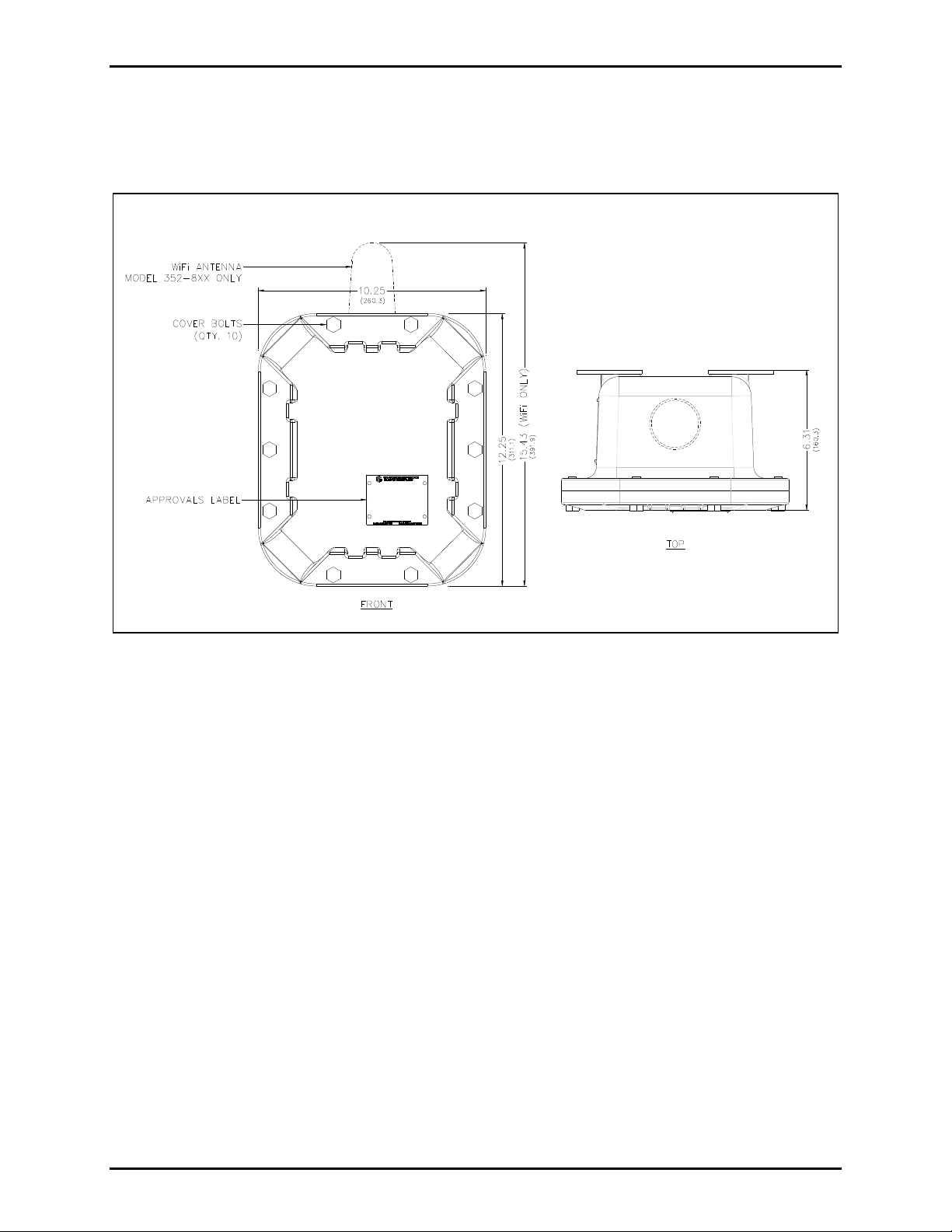
Figure 1. Mode 352-8xx Div. 1
VoIP WiFi Page Phone
GAI-Tronics Corporation 400 E. Wyomissing Ave. Mohnton, PA 19540 USA
610-777-1374 800-492-1212 Fax: 610-796-5954
V
ISIT WWW.GAI-TRONICS.COM FOR PRODUCT LITERATURE AND MANUALS
Page 2

Pub. 42004-486B
Model 352-7xx and 352-8xx Division 1 VoIP Page Phones – Wired & WiFi Page 2 of 29
Table 1. Model Chart
Model Description
Handset Models
352-712
352-722
352-732
352-812
352-822
352-713
352-723
352-733
352-813
352-823
352-711
352-721
Div. 1 VoIP AC Page Phone
Div. 1 VoIP DC Page Phone
Div. 1 VoIP PoE Page Phone
Div. 1 VoIP WiFi AC Page Phone
Div. 1 VoIP WiFi DC Page Phone
Headset Models
Div. 1 VoIP AC Page Phone
Div. 1 VoIP DC Page Phone
Div. 1 VoIP PoE Page Phone
Div. 1 VoIP WiFi AC Page Phone
Div. 1 VoIP WiFi DC Page Phone
Amplifier-Only Models
Div. 1 VoIP AC Page Phone
Div. 1 VoIP DC Page Phone
352-811
352-821
Div. 1 VoIP WiFi AC Page Phone
Div. 1 VoIP WiFi DC Page Phone
System Requirements and Limitations
VoIP
Two VoIP telephones can be connected in a peer-to-peer configuration without the need for a LAN,
however, a 10/100 BaseT Ethernet with SIP server is required for systems containing three or more VoIP
Telephones. Conferences are limited by the customer’s LAN media capabilities and the services
available at each end point.
VoIP WiFi
Two telephones can communicate wirelessly in a peer-to-peer configuration without the need for a LAN
connection. However, a wireless pick-up point connected to a 10/100 BaseT Ethernet with SIP server is
required for systems containing three or more WiFi telephones (or a combination of WiFi and hardwiredconnected VoIP telephones). Conferences are limited by the customer’s LAN media capabilities and the
services available at each end point.
f:\standard ioms - current release\42004 instr. man uals\42004-486b.doc
12/14
Page 3

Pub. 42004-486B
Model 352-7xx and 352-8xx Division 1 VoIP Page Phones – Wired & WiFi Page 3 of 29
Multicast Paging
In addition to direct point-to-point dialing (peer-to-peer), directly or via a SIP server, each telephone is
capable of receiving a Multicast broadcast. Multicast allows a single audio stream to be sent to multiple
end points simultaneously, to achieve multi-point paging or Public Address functionality over IP.
Multicast requires the use of a SIP server or IP device that specifically supports Multicast functionality
and each telephone must be configured (enabled) to receive Multicast packets.
Tips for VoIP Subscribers
If you have or are thinking of subscribing to an interconnected VoIP service, you should:
Provide your accurate physical address to your interconnected VoIP service provider to ensure that
emergency services can quickly be dispatched to your location.
Be familiar with your VoIP service provider’s procedures for updating your address, and promptly
update address information in the event of a change.
If your power is out or your internet connection is down, be aware that your VoIP service may not
work. Consider installing a backup power supply, maintaining a traditional telephone line, or having
a wireless telephone as a backup.
If you have questions about VoIP in general, see http://www.fcc.gov/cgb/consumerfacts/voip.html.
Features and Functions
GAI-Tronics VoIP telephones include the following features:
SIP compatible (RFC3261)
Real-time alarm reporting via email or syslog
Power-over-Ethernet compatible (Power Mode A, Class 0)
Configurable via web page, serial link or download
Four configurable auxiliary inputs and two configurable voltage-free contact outputs
f:\standard ioms - current release\42004 instr. man uals\42004-486b.doc
12/14
Page 4

Pub. 42004-486B
Model 352-7xx and 352-8xx Division 1 VoIP Page Phones – Wired & WiFi Page 4 of 29
Installation
Installation Guidelines
These enclosures must be installed by trained, qualified and competent personnel. Installation must
comply with state and national regulations, as well as safety practices for this type of equipment.
CAUTION
indicated on the approval listing in the “Specifications” section of this manual. Such installation
may cause a safety hazard and consequent injury or property damage.
The mounting location must be flat and provide proper clearance, rigidity and strength to support the
enclosure and all contained devices.
WARNING
steel mounting bolts and washers, or washer head bolts.
WARNING
Insure proper grounding to protective earthing.
WARNING
are removed, the cover must be adequately supported.
ATTENTION
accordance with the National Electric al Code or applicable local codes.
Inspect and clean the machined flange flame joint surfaces of both the cover and box. Surfaces must be
smooth, free of nicks, scratches, dirt or any foreign particle build-up that would prevent a proper seal.
Surfaces must seat fully against each other to provide a proper explosion-proof joint. Clean surfaces by
wiping with a clean lint-free cloth.
Do not install this equipment in hazardous areas other than those
Securely fasten the enclosure to the mounting location, using 3/8-inch diameter
Do not disconnect equipment while energized.
The front cover is not hinged to the rear enclosure. When the cover bolts
Installation should be performed by qualified personnel and only in
Apply a light coat of Killark “LUBG” lubricant to flange surfaces and close the cover. Install and tighten
all cover bolts to 30 ft-lbs. Make certain no cover bolts are omitted. Use only those bolts supplied with
the enclosure.
When installing any GAI-Tronics telephone equipment, please adhere to the following guidelines to
ensure the safety of all personnel:
Electrostatic Discharge (ESD) Protection: Your telephone has an earth ground terminal provision.
Ensure that it is connected to ground in accordance with all local safety regulations and the National
Electrical Code (NEC). Grounding must be ensured for safe and stable communications. Do not use
long and coiled ground wires. Trim ground wires to the required length. Please note proper
grounding does not eliminate the need for lightning protection for the telephone or the telephone
system.
NEVER install the telephone during a lightning storm.
Install a Cat5 data line lightning su rge prot ec tor on any phone installed where the phone or phone
cable is at risk of being exposed to lightning strikes. The lightning arrestor must be installed as close
to the phone as possible in a non-hazardous environment. The lightning arrestor must not be installed
within the telephone enclosure.
USE CAUTION when installing or modifying Cat5 data lines.
f:\standard ioms - current release\42004 instr. man uals\42004-486b.doc
12/14
Page 5

Pub. 42004-486B
Model 352-7xx and 352-8xx Division 1 VoIP Page Phones – Wired & WiFi Page 5 of 29
Mounting
NOTE: The mounting surface must be able to support the weight of the telephone, which is 31 lbs.
The enclosure must be securely fastened with 3/8-inch diameter steel mounting bolts located on all four
mounting feet. Stainless steel hardware is recommended in outdoor applications. Refer to Figure 2. The
suggested mounting height is 48 inches to the bottom of the enclosure.
OTE: Refer to the Killark Installation, Operation, and Maintenance Data Sheet for the Killark Part. No.
N
EXB-684 N34 Base Enclosure (enclosed with the unit) for additional information.
Figure 2. Model 352 Series Division 1 VoIP Page Phone Enclosure Mounting Details
Cable Entries
Refer to Figure 3 for the NPT conduit entries. Ensure any unused openings are sealed with proper fittings
per local standards. Use field wiring suitable for the ambient temperature. Any conduit NPT plugs
(blanking elements) must be explosion-proof with a Type 4X rating.
Figure 3. Model 352-7xx and 352-8xx Series VoIP/WiFi Conduit Entries
f:\standard ioms - current release\42004 instr. man uals\42004-486b.doc
12/14
Page 6

Pub. 42004-486B
Model 352-7xx and 352-8xx Division 1 VoIP Page Phones – Wired & WiFi Page 6 of 29
Hardware Description
External
Model 352-7x2 and 352-8x2 contain a handset with an approved cable gland, standard keypad, volume
control button, and applicable approval labeling. The handset rests on a cradle, which has a magnetic
reed switch to signal an off-hook condition. The enclosure is sealed with ten cover mounting bolts
located around the perimeter of the enclosure’s flange. The VoIP WiFi version includes a weatherproof
WiFi antenna mounted to the top of the enclosure. See Figure 4.
Figure 4. Model 352-7x2 and 352-8x2 Division 1 VoIP Page Phone
f:\standard ioms - current release\42004 instr. man uals\42004-486b.doc
12/14
with Handset
Page 7

Pub. 42004-486B
Model 352-7xx and 352-8xx Division 1 VoIP Page Phones – Wired & WiFi Page 7 of 29
Models 352-7x3 and 352-8x3 are fitted with a removable headset and hook bracket. The headset is
activated by flipping its mounting hook forward. The enclosure is sealed with ten cover mounting bolts
located around the perimeter of the enclosure’s flange. The VoIP WiFi version includes a weatherproof
WiFi antenna mounted to the top of the enclosure. See Figure 5.
Figure 5. Model 352-7x3 and 352-8x3 Division 1 VoIP Page Phone
with Headset
f:\standard ioms - current release\42004 instr. man uals\42004-486b.doc
12/14
Page 8
Pub. 42004-486B
Model 352-7xx and 352-8xx Division 1 VoIP Page Phones – Wired & WiFi Page 8 of 29
Models 352-7x1 and 352-8x1 do not have any external components for two-way communication. These
versions are designed for use as amplifiers only. The enclosure is sealed with ten cover mounting bolts
located around the perimeter of the enclosure’s flange. The VoIP WiFi version includes a weatherproof
WiFi antenna mounted on the top of the enclosure. See Figure 6.
Figure 6. Model 352-7x1 and 352-8x1 WiFi Page Phone
f:\standard ioms - current release\42004 instr. man uals\42004-486b.doc
12/14
Page 9

Pub. 42004-486B
Model 352-7xx and 352-8xx Division 1 VoIP Page Phones – Wired & WiFi Page 9 of 29
Internal
The Model 352-7xx VoIP Page Phone include a power supply, input power terminal block and shield in
the rear enclosure. The front cover has the main VoIP Carrier PCBA and VoIP Circuit PCBA, Amplifier
PCBA, Keypad PCBA, and handset barrier. Amplifier-only versions do not include a Keypad PCBA and
barrier. See Figure 7 for parts layout.
Figure 7. Model 352-7xx Div. 1 VoIP Page Phone - Internal View
f:\standard ioms - current release\42004 instr. man uals\42004-486b.doc
12/14
Page 10

Pub. 42004-486B
Model 352-7xx and 352-8xx Division 1 VoIP Page Phones – Wired & WiFi Page 10 of 29
The Model 352-8xx VoIP WiFi Page Phones include a power supply, input power terminal block, shield,
and Div. 1 external antenna. The front cover has the main VoIP/WiFi Carrier PCBA and VoIP Circuit
PCBA, WiFi module, Amplifier PCBA, Keypad PCBA and handset barrier. Amplifier-only versions do
not include a keypad and barrier. See Figure 8 for parts layout.
Figure 8. Model 352-8xx Div. 1 WiFi Page Phone
f:\standard ioms - current release\42004 instr. man uals\42004-486b.doc
12/14
Page 11

Pub. 42004-486B
Model 352-7xx and 352-8xx Division 1 VoIP Page Phones – Wired & WiFi Page 11 of 29
Wir in g
WARNING
The front cover is not hinged to the rear enclosure. When the cover bolts
are removed, the cover must be adequately supported.
1. While supporting the front cover, remove the ten cover bolts on the enclosure flange. Pull the front
cover far enough away to expose the internal connections. Flip the front cover 180º to the left, and
attach the front cover to the rear enclosure using the top left bolt hole. Rotate the cover
approximately 10º from vertical and place a second bolt in the bottom left rear enclosure hole. Allow
the cover to rotate against the bottom bolt. Hand-tighten both bolts to secure. Do not over tighten.
CAUTION
Do not scratch or nick the flanges of the front cover or rear enclosure.
2. For wired versions, plug the incoming Cat5 data line to the network Cat5 cable receptacle on the
underside of the VoIP PCBA. See Figure 10. Remove the power supply cover in the rear enclosure
for access to the terminal block.
3. Remove the power supply cover in the rear enclosure for access to the input power terminal block.
Connect incoming power to the 3-point terminal in the rear enclosure.
4. Route the speaker connection wire on the left side of the power supply to the P4 speaker plug on the
front cover. Terminate the wires per the PCBA silk screen text.
5. Reattach the power supply cover using the two screws previously removed from the cover.
Install any additional connections as indicated below. Refer to Figure 10 for wiring details. Refer to
Table 4 on page 14 for the recommended conductor sizes.
Figure 9. Installation and Maintenance Configuration
f:\standard ioms - current release\42004 instr. man uals\42004-486b.doc
12/14
Page 12

Pub. 42004-486B
Model 352-7xx and 352-8xx Division 1 VoIP Page Phones – Wired & WiFi Page 12 of 29
Figure 10. Internal PCBA Connections
Network Cable
Connect a Cat5 or Cat5e UTP cable with an RJ45 connector between the Local Area Network (LAN) and
the VoIP PCBA. See Figure 10.
Power-Over-Etherne t (POE)
Connect power to the system as indicated in your POE equipment manual. (Power Mode A, Class 0)
f:\standard ioms - current release\42004 instr. man uals\42004-486b.doc
12/14
Page 13

Pub. 42004-486B
Model 352-7xx and 352-8xx Division 1 VoIP Page Phones – Wired & WiFi Page 13 of 29
I/O
Inputs
Four auxiliary inputs have been provided for customer use. Terminations for these inputs are provided on
terminal block P12. Connect each input between the desired input (INPUT 1–4) and common (GND) on
terminal block P12. Refer to the “Inputs” section of Pub. 42004-396 for programming instructions for
these inputs.
Table 2. Auxiliary Inputs – P12
Pin Label Function
1 IN4 Input 4
2 COM Common
3 IN3 Input 3
4 COM Common
5 IN2 Input 2
6 COM Common
7 IN1 Input 1
8 COM Common
Inputs have an internal pull-up resistor and need to be 3.3 V dc tolerant.
Outputs
Two outputs have been provided for customer use. Terminations for these outputs are provided on
connector P10.
The function of each output is configurable. Outputs can be configured for one of the following modes:
On, Off, Pulse, Mute, Ring, Call, Connect, Hook, In Use, Ring Cadence, Ring Out, Page, Registered, or
Emergency. In some modes, the duration of the activation or on/off times can also be set. Refer to the
“Logic Settings” section of GAI-Tronics Pub. 42004-396, “VoIP Telephone Configuration Guide” for
more details.
Table 3. Output Contacts – P10
Pin Label Description
1 C1 Common Output 1
2 NO1 Normally Open Output 1
3 C2 Common Output 2
4 NO2 Normally Open Output 2
Relay capacity is 5 amps, 30 V ac/V dc.
f:\standard ioms - current release\42004 instr. man uals\42004-486b.doc
12/14
Page 14

Pub. 42004-486B
Model 352-7xx and 352-8xx Division 1 VoIP Page Phones – Wired & WiFi Page 14 of 29
Table 4. Recommended Cabling
Cable Use Size
LAN Cat5 or Cat5e UTP cable with an RJ45 connector
Power Two-conductor, No. 18 AWG is typical
Inputs Two-conductor, No. 22 AWG is typical
Output contacts Two-conductor, No. 18 AWG is typical
Speaker Two or three-conductor, No. 18 AWG is typical
Status Indication
Power
The Power LED located on the VoIP PCBA illuminates when power is applied to the telephone. Refer to
Figure 11 for location.
Heartbeat
The Heartbeat LED located on the VoIP PCBA will flash when the telephone is operational over the
WLAN. Refer to Figure 11 for location.
EACT
The EACT LED located on the VoIP PCBA will turn ON when VoIP PCBA is connected to an Ethernet
device and flash when data is being transmitted. Refer to Figure 11 for location.
WiFi Activity ( WiFi Units Only)
The WiFi Activity LED located on the WiFi module will turn ON when the VoIP Telephone is powered
and flash when data is being transmitted. Refer to Figure 11 for location.
WiFi Ready (WiFi Units Only)
The WiFi Ready LED a green LED on the RJ-45 connecter J2 located on the VoIP carrier PCBA
illuminates when the WiFi Interface is ready to connect to a wireless Network. Refer to Figure 11 for
location.
WiFi Connected (WiFi Units Only)
The WiFi Connected LED a yellow LED on the RJ-45 connecter J2 located on the VoIP carrier PCBA
illuminates when the WiFi Interface is connected to a wireless network or device. Refer to Figure 11 for
location.
f:\standard ioms - current release\42004 instr. man uals\42004-486b.doc
12/14
Page 15

Pub. 42004-486B
Model 352-7xx and 352-8xx Division 1 VoIP Page Phones – Wired & WiFi Page 15 of 29
Figure 11. VoIP Carrier PCBA Component Locations
Attach the Front Cover
After all adjustments have been completed, inspect and clean the machined flange joint surfaces of both
the cover and box. Surfaces must be smooth, free of nicks, scratches dirt or any foreign particle build-up
that would prevent a proper seal. Surfaces must seat fully against each other to provide a proper
explosion-proof joint. Clean surfaces by wiping with a clean lint-free cloth.
Apply a light coat of Killark “LUBG” lubricant to flange surfaces and close the cover. Install and tighten
all cover bolts to 30 ft-lbs. Make certain no cover bolts are omitted. Use only those bolts supplied with
the enclosure.
NOTE: Refer to the Killark Installation, Operation, and Maintenance Data Sheet for the Killark Part. No.
EXB-684 N34 Base Enclosure (enclosed with the unit) for additional information.
f:\standard ioms - current release\42004 instr. man uals\42004-486b.doc
12/14
Page 16

Pub. 42004-486B
Model 352-7xx and 352-8xx Division 1 VoIP Page Phones – Wired & WiFi Page 16 of 29
External Controls
Handset Receiver Volume Control
A push-button switch is provided on the face plate for adjustment of the handset receiver volume. When
pressed, it incrementally decreases the volume from 20 dB to 12 dB, to 0 dB, and back up to 20 dB of the
original signal. After the end of each call the signal level is automatically set to 20 dB.
Maximum (Handset Receiver) Level Remote Control
The receiver volume level can be controlled remotely by changing the setting in the configuration file.
Refer to the “Handset Volume Setting in the Audio Setting” section in Pub. 42004-396 for programming
instructions.
Programming
The installer should ensure that the network is configured to allow VoIP communications (using the SIP
protocol) between the desired locations before attempting to configure the GAI-Tronics VoIP Telephones.
First Time WiFi Interface Setup
Configuration of the WiFi interface is required to set up security of the WLAN unit’s connection.
Power the telephone by connecting 24–48 V dc to P5.
While the VoIP telephone’s WiFi interface is still using the factory default configuration it will be an
Access Point to a network called
the HF-A11_AP network. When the PC shows that it is connected to the HF-A11_AP network the
yellow LED on the WiFi interface should be ON.
When you are connected to the HF-A11_AP network open a web browser on the PC and type
HF-A11_AP. Using a PC/laptop with wireless capability, connect to
10.10.100.254 into the address field and press Enter. The HF-A11_AP WiFi Log In Window will open.
admin for both the user and for the password, then Log In. The Working Mode Configuration Web
Enter
page will open. Select
If you are having a problem connecting to the
adapter is set to DCHP (Obtain an IP address automatically).
STA Mode then click the Apply button.
HF-A11_AP network verify that the PC’s wireless network
Figure 12. WiFi Interface Working Mode Configuration Web page
f:\standard ioms - current release\42004 instr. man uals\42004-486b.doc
12/14
Page 17

Pub. 42004-486B
Model 352-7xx and 352-8xx Division 1 VoIP Page Phones – Wired & WiFi Page 17 of 29
After the configuration has updated the Web page will show Set Successfully, Restart to use new setting.
Then click on the STA Interface Setting selection. The STA Interface Setting Web Page will open.
Figure 13. WiFi Interface STA Interface Setting Web page
Click the Search button in the AP’S SSID section to find the WiFi network that the VoIP Telephone will
operate in. The Site Survey Web page will open showing all available networks. Select the desired
network and click the Apply button.
Figure 14. WiFi Interface Site Survey Web page
A reminder window for entering the WEP Key will pop up. Click the OK button.
When the STA Interface Setting Web page opens again, the AP’s SSID, Security Mode and Encryption
Type fields will automatically be filled in. Now enter the
WEP Key or Pass Phrase for the selected
network and click the Apply button.
If the VoIP telephone is not within the range of the wireless network that it is being configured to operate
in, the AP’s SSID, Security Mode, Encryption Type and WEP Key or Pass Phrase fields will need to be
manually filled in before you click the Apply button.
f:\standard ioms - current release\42004 instr. man uals\42004-486b.doc
12/14
Page 18

Pub. 42004-486B
Model 352-7xx and 352-8xx Division 1 VoIP Page Phones – Wired & WiFi Page 18 of 29
After the configuration has updated the Web page will show Set Successful ly, Restart to use ne w
setting
open. In the Restart Module section click the
. Then click on the Device Management selection. The Device Management Web Page will
Restart button.
Figure 15. WiFi Interface Device Management Web page
When the WiFi module is restarting the web page will show Rebooting…. Both LEDs on the RJ-45 jack
J2 will turn OFF for several seconds while the WiFi interface is restarting. The green LED will turn ON
first when the WiFi interface is done restarting. The yellow LED will turn ON if the WiFi interface can
connect to the newly configured network.
If the VoIP Telephone does not connect to the wireless network due to an incorrect WEP Key or Pass
Phrase, follow the instructions in the next section, “Change WiFi Interface Configuration.”
NOTE: The WiFi module is no longer an Access point to its own network (HF-A11_AP). The WiFi
module should now be connected to or trying to connect to the newly configured wireless network. The
browser Web page will not change from showing Rebooting because the PC is no longer connected to the
HF-A11_AP network.
f:\standard ioms - current release\42004 instr. man uals\42004-486b.doc
12/14
Page 19

Pub. 42004-486B
Model 352-7xx and 352-8xx Division 1 VoIP Page Phones – Wired & WiFi Page 19 of 29
Change WiFi Interface Configuration
To change the configuration of the WiFi interface first press the RLOAD button (PB1) for 10 seconds to
return the WiFi interface to its default settings. The RLOAD button is located on the VoIP telephone
PCBA near the WiFi module and J2. Both LEDs on the RJ-45 jack (J2) will turn OFF for several seconds
while the WiFi interface is resetting. Wait for the green LED to turn ON before trying to connect to the
HF-A11_AP network.
With the default settings loaded and the green LED on the RJ-45 jack (J2) ON follow the instructions in
the “First Time WiFi Interface Setup” section on page 16 to connect the HF-A11_AP network and change
the configuration settings.
WARNING
After changing the WiFi Interface configuration if the VoIP telephone has been
configured for DHCP, the telephone’s power must be cycled before the telephone will connect to the
wireless network. After power is reapplied, and the green and yellow LEDs on the RJ-45 Jack (J2) are
ON, and the HEART BEAT LED on the VoIP Telephone PCBA is flashing, you can go to the next
section, “VoIP PCBA Setup” and start setting up the VoIP telephone configuration.
f:\standard ioms - current release\42004 instr. man uals\42004-486b.doc
12/14
Page 20

Pub. 42004-486B
Model 352-7xx and 352-8xx Division 1 VoIP Page Phones – Wired & WiFi Page 20 of 29
VoIP PCBA Setup
Verify the PC is connected to the same network as the VoIP telephone.
The easiest way to get started is to make a network connection to the unit and log on via a web browser.
The unit is initially set with a static IP address:
IP address 192.168.1.2
A user name and password will be requested. The initial factory settings are:
User Name user
Password password
Changing the user name and password is recommended. This security measure helps to prevent
unauthorized changes to the VoIP Telephone Interface’s configuration.
VoIP PCBA Initial Network Configuration
Each VoIP PCBA must be set up for the network prior to installation. Assign a local ID, domain, proxy,
and registrar.
Assign a host name The host name provides identification of the different VoIP PCBAs on the
network.
Test Verify that calls can be made successfully.
Maintain Monitor alarms. Set up auto-updates.
Refer to Pub. 42004-396 for detailed programming instructions for this VoIP device.
Alternative Configuration Methods
There are three methods for configuring GAI-Tronics Handset VoIP telephones:
Web pages
Configuration file
Command Line interface (CLI)
Web pages (held within the telephone) can be accessed over the network using a browser such as Internet
Explorer™, to view and change settings within a single unit.
Configuration files are ASCII text files containing configuration options that can be read and edited by
VCONF (a dedicated software configuration tool), or directly by a knowledgeable user. The telephone
can automatically download a configuration file from the network, providing a controlled method of
configuring multiple telephones.
The telephone can also be configured using a command line interface, either via the local serial port or
remotely via a TELNET session over the network.
f:\standard ioms - current release\42004 instr. man uals\42004-486b.doc
12/14
Page 21

Pub. 42004-486B
Model 352-7xx and 352-8xx Division 1 VoIP Page Phones – Wired & WiFi Page 21 of 29
Operation
Model 352-7x2 and 352-8x2 Handset Operation
1. Lift the handset to place a call.
2. The handset receiver volume control, located on the front cover keypad, can be adjusted to the desired
level by pressing the volume control push button.
3. Dial the desired number.
4. After completion of the call, place the handset on hook.
Figure 16. WiFi Page Phone – Handset Version
f:\standard ioms - current release\42004 instr. man uals\42004-486b.doc
12/14
Page 22

Pub. 42004-486B
Model 352-7xx and 352-8xx Division 1 VoIP Page Phones – Wired & WiFi Page 22 of 29
Model 352-7x3 and 352-8x3 Headset Operation
1. To connect the headset, plug it into the flexible plug on the front of the telephone by removing the
sealing cap from the receptacle, aligning the connector pins, and screwing the two ends together. See
Figure 17.
NOTE: The headset can be connected while the unit is powered.
Figure 17. On-hook Configuration – Div. 1 WiFi Page Phone – Headset Version
2. To place a call, remove the headset from the headset activation bracket and flip the headset bracket
forward from its pre-set position.
3. The handset receiver volume control, which is located on the front cover keypad, can be adjusted to
the desired level by pressing the volume control push button.
4. Dial the desired number.
f:\standard ioms - current release\42004 instr. man uals\42004-486b.doc
12/14
Page 23

Pub. 42004-486B
Model 352-7xx and 352-8xx Division 1 VoIP Page Phones – Wired & WiFi Page 23 of 29
5. Flip the headset activation bracket to its vertical pre-set position to hang up. If applicable, place the
headset on the bracket after the completion of the call. Otherwise, disconnect the flexible receptacle
and plug by unscrewing the two ends, and pulling them apart. When disconnected, reattach the
sealing cap to the end of the receptacle.
Figure 18. Off-hook Configuration – Div. 1 WiFi Page Phone – Headset Version
f:\standard ioms - current release\42004 instr. man uals\42004-486b.doc
12/14
Page 24

Pub. 42004-486B
Model 352-7xx and 352-8xx Division 1 VoIP Page Phones – Wired & WiFi Page 24 of 29
Amplifier Paging (Mul ticast Broadcast)
When making a Multicast call, the SIP server or IP device will send a paging request to a specific IP
address and expect multiple telephones to accept and play the subsequent audio. GAI-Tronics VoIP
telephones can be programmed for up to eight Multicast addresses to permit the receipt of Multicast
broadcasts from different sources or to enable zoning of broadcasts. Each Multicast address can be
assigned a priority (via programming) to define which can override which. A telephone with Multicast
enabled can still make and receive normal calls. Normal calls can be assigned a priority level, defining
whether calls can override Multicasts or vice versa.
Monitoring and Reporting
Each telephone can recognize and generate several hardware and configuration fault condition alarms.
These alarms can be signaled to a remote site using three methods:
Syslog output over TCP
SMTP mail message
Telephone Management Application (TMA) software (purchased separately)
Available alarms are:
Handset integrity loop (if applicable)
Configuration error
Cold reset (power cycle)
Warm reset (internal command)
Keypad error, such as a stuck button (if applicable)
Key hook (off-hook status, if applicable)
Register fail
Audio Path Test (speaker/microphone test)
f:\standard ioms - current release\42004 instr. man uals\42004-486b.doc
12/14
Page 25

Pub. 42004-486B
Model 352-7xx and 352-8xx Division 1 VoIP Page Phones – Wired & WiFi Page 25 of 29
Maintenance
Service
If your telephone requires depot service, contact your Regional Service Center for a return authorization
number (RA#). Equipment should be shipped prepaid to GAI-Tronics with a return authorization number
and a purchase order number. If the equipment is under warranty, repairs will be made without charge.
Please include a written explanation of all defects to assist our technicians in their troubleshooting efforts.
Call 800-492-1212 inside the USA or 610-777-1374 outside the USA for help identifying the Regional
Service Center closest to you.
Troubleshooting
Table 5. Troubleshooting Chart
Problem Possible Solution
Low volume in handset
or headset
High volume in handset
or headset
Front panel push buttons
are not operational
Inputs not operational
Outputs not operational
Cannot make or receive
calls
Increase the volume setting using the Volume Adjust button on the front
panel.
Decrease the volume setting using the Volume Adjust button on the front
panel.
Verify the push buttons are properly configured.
Check the input connections.
Verify the inputs are properly configured.
Check the output connections.
Verify the outputs are properly configured.
Check the connection of the LAN cable.
Verify that power is applied to the unit.
Verify the LAN parameters have been configured properly.
Verify the telephone has been set up on the network.
Check the power connections.
No power indication
f:\standard ioms - current release\42004 instr. man uals\42004-486b.doc
12/14
Check fuses. Replace fuses with identical type/ratings.
If using POE, check the operation of the POE equipment.
Page 26

Pub. 42004-486B
Model 352-7xx and 352-8xx Division 1 VoIP Page Phones – Wired & WiFi Page 26 of 29
Specification s
Power Requirements
AC/DC Input
AC Power Supply
Input voltage ...................................................................... 120 V ac or 230 V ac, 50/60 Hz, +/−10%
DC Power Supply
Input voltage ...................................................................................................................... 24–48 V dc
Power-over-Ethernet ......................................................................................................................... 12.95 W
802.11af compliant (via RJ45) Power Mode A, Class 0
Station Speaker Load
(8-ohm load)
24 V DC
48 V DC
120 V AC
230 V AC
Idle 325 mA/8W 180 mA/8.5 W 120 mA/15 VA 100 mA/23VA
4-watt output
(default setting)
620 mA/15W 350 mA/17 W 275 mA/33 VA 130 mA/30 VA
30-watt output 2200mA/53W 1100 mA/53 W 800 mA/96 VA 400 mA/92 VA
VoIP Network
Network ...................................................................................... 10/100 BaseT Ethernet RJ45, Cat5/6 UTP
Static IP or DHCP STUN client (NAT traversal) address provisioning
Call control signaling ................................. SIP (RFC3261 compliant) Loose routing call control signaling
WiFi Network
Standards ........................................................................................................................... IEEE 802.11b/g/n
Frequency ........................................................................................................................... 2.412–2.484 GHz
Configuration .......................................................................................................... Embedded web server
Configuration file download
Direct serial connection
Password protection
Handset Audio
Analog microphone gain ........................................................................................................................30 dB
Analog earpiece gain ............................................................................................................ Default: +20 dB
Setting 2: +12 dB
Setting 3: 0 dB
Frequency response .................................................................................................................... 250–6500 Hz
Frequency response flatness ................................................................................................... 3 dB minimum
THD @ 1 kHz ........................................................................................................................... 1% minimum
f:\standard ioms - current release\42004 instr. man uals\42004-486b.doc
12/14
Page 27

Pub. 42004-486B
Model 352-7xx and 352-8xx Division 1 VoIP Page Phones – Wired & WiFi Page 27 of 29
Speaker Audio
Output level to 8-ohm speaker (ac/dc version) ..................................................................... 30 W maximum
Gain below limiter (ac/dc version).........................................................................................................27 dB
Output level to 8-ohm speaker (PoE version) ......................................................................... 3 W maximum
Gain below limiter (PoE version) ..........................................................................................................10 dB
VOX activation time .......................................................................................................................... 20 msec
VOX hold time ........................................................................................................................................ 2 sec
Frequency response .................................................................................................................... 250–6500 Hz
Frequency response flatness ................................................................................................... 3 dB minimum
THD @ 1 kHz, 24 W ................................................................................................................ 1% minimum
THD @ 1 kHz, 30 W ................................................................................................................ 3% minimum
f:\standard ioms - current release\42004 instr. man uals\42004-486b.doc
12/14
Page 28

Pub. 42004-486B
Model 352-7xx and 352-8xx Division 1 VoIP Page Phones – Wired & WiFi Page 28 of 29
Inputs
Keypad* ...................................................................................................................................... 3 4 matrix
Configurable inputs (quantity = 4) ............................................................ Internal pull-up 3.3 V dc tolerant
*Not available on all models.
Outputs
Output 1 ............................................................................. 5 amps @ 30 V ac/dc maximum (resistive load)
Output 2 ............................................................................. 5 amps @ 30 V ac/dc maximum (resistive load)
Indicators
Internal on VoIP Circuit Board ................................................................ Power, Heartbeat, & EACT LEDs
Internal on VoIP Carrier Board (WiFi Unit only) .... WiFi Activity, WiFi Ready, & WiFi Connected LEDs
Monitoring and reporting ........................... Real-time over TCP/IP proprietary Syslog application or email
Embedded SMTP client
Automatic fault reporting
Environmental
Operating temperature .......................................................................... −4º F to +140º F (−20º C to +60º C)
Weather resistance ...................................................................................................... IP66, NEMA Type 4X
Humidity ...................................................................................................................... 95% non-condensing
Mechanical
Enclosure .............................................................................. Cast aluminum with aluminized lacquer paint
Handset Cord ....................................................... “G” style handset/PVC 6-foot extended length (standard)
Connection ............................................................................................................................ RJ45 receptacle
Dimensions, outside (VoIP) .................... 10.25 W 12.25 H 9.50 D inches (260.3 311.1 241.3 mm)
Dimensions, outside (WiFi) .................... 10.25 W 15.43 H 9.50 D inches (260.3 391.9 241.3 mm)
Mounting .................................................. Wall or column, four 3/8-inch (10 mm) mounting feet with slots
Shipping weight ................................................................................................................ 33.0 lbs. (15.0 kg)
Net weight ......................................................................................................................... 31.0 lbs. (14.1 kg)
Approvals
With antenna
NRTL listed ............................................................ Hazardous locations Class I, Division 1, Groups C & D
(USA and Canada) Class II, Groups F & G
Class III
Part 15 compliant
Temperature code T6 – gas
T4a – dust
Without antenna
NRTL listed ....................................................... Hazardous locations Class I, Division 1, Groups B, C & D
(USA and Canada) Class II, Groups F & G
Class III
Part 15 compliant
Temperature code T6 – gas
T4a – dust
f:\standard ioms - current release\42004 instr. man uals\42004-486b.doc
12/14
Page 29

Pub. 42004-486B
Model 352-7xx and 352-8xx Division 1 VoIP Page Phones – Wired & WiFi Page 29 of 29
User Instructions (USA)
This equipment has been tested and found to comply with the limits for a Class A digital device, pursuant to part 15 of the FCC
Rules. These limits are designed to provide reasonable protection against harmful interference when the equipment is operated in
a commercial environment. This equipment generates, uses, and can radiate radio frequency energy and, if not installed and used
in accordance with the instruction manual, may cause harmful interference to radio communications. Operation of this
equipment in a residential area is likely to cause harmful interference in which case the user will be required to correct the
interference at his own expense.
f:\standard ioms - current release\42004 instr. man uals\42004-486b.doc
12/14
Page 30

Warranty
Equipment. GAI-Tronics warrants for a period of one (1) year from the date of shipment, that any
GAI-Tronics equipment supplied hereunder shall be free of defects in material and workmanship, shall
comply with the then-current product specifications and product literature, and if applicable, shall be fit
for the purpose specified in the agreed-upon quotation or proposal document. If (a) Seller’s goods prove
to be defective in workmanship and/or material under normal and proper usage, or unfit for the purpose
specified and agreed upon, and (b) Buyer’s claim is made within the warranty period set forth above,
Buyer may return such goods to GAI-Tronics’ nearest depot repair facility, freight prepaid, at which time
they will be repaired or replaced, at Seller’s option, without charge to Buyer. Repair or replacement shall
be Buyer’s sole and exclusive remedy. The warranty period on any repaired or replacement equipment
shall be the greater of the ninety (90) day repair warranty or one (1) year from the date the original
equipment was shipped. In no event shall GAI-Tronics warranty obligations with respect to equipment
exceed 100% of the total cost of the equipment supplied hereunder. Buyer may also be entitled to the
manufacturer’s warranty on any third-party goods supplied by GAI-Tronics hereunder. The applicability
of any such third-party warranty will be determined by GAI-Tronics.
Services. Any services GAI-Tronics provides hereunder, whether directly or through subcontractors,
shall be performed in accordance with the standard of care with which such services are normally
provided in the industry. If the services fail to meet the applicable industry standard, GAI-Tronics will
re-perform such services at no cost to buyer to correct said deficiency to Company's satisfaction provided
any and all issues are identified prior to the demobilization of the Contractor’s personnel from the work
site. Re-performance of services shall be Buyer’s sole and exclusive remedy, and in no event shall GAITronics warranty obligations with respect to services exceed 100% of the total cost of the services
provided hereunder.
Warranty Periods. Every claim by Buyer alleging a defect in the goods and/or services provided
hereunder shall be deemed waived unless such claim is made in writing within the applicable warranty
periods as set forth above. Provided, however, that if the defect complained of is latent and not
discoverable within the above warranty periods, every claim arising on account of such latent defect shall
be deemed waived unless it is made in writing within a reasonable time after such latent defect is or
should have been discovered by Buyer.
Limitations / Exclusions. The warranties herein shall not apply to, and GAI-Tronics shall not be
responsible for, any damage to the goods or failure of the services supplied hereunder, to the extent
caused by Buyer’s neglect, failure to follow operational and maintenance procedures provided with the
equipment, or the use of technicians not specifically authorized by GAI-Tronics to maintain or service the
equipment. THE WARRANTIES AND REMEDIES CONTAINED HEREIN ARE IN LIEU OF AND
EXCLUDE ALL OTHER WARRANTIES AND REMEDIES, WHETHER EXPRESS OR IMPLIED BY
OPERATION OF LAW OR OTHERWISE, INCLUDING ANY WARRANTIES OF
MERCHANTABILITY OR FITNESS FOR A PARTICULAR PURPOSE.
Return Policy
If the equipment requires service, contact your Regional Service Center for a return authorization number
(RA#). Equipment should be shipped prepaid to GAI-Tronics with a return authorization number and a
purchase order number. If the equipment is under warranty, repairs or a replacement will be made in
accordance with the warranty policy set forth above. Please include a written explanation of all defects to
assist our technicians in their troubleshooting efforts.
Call 800-492-1212 (inside the USA) or 610-777-1374 (outside the USA) for help identifying the
Regional Service Center closest to you.
(Rev. 10/06)
 Loading...