

Page 1

Pub. 42004-454A
GAI-TRONICS® CORPORATION
A HUBBELL COMPANY
Model 352-001, 352-002, 352-003, and 352-004
Division 1
Confidential ity Notice
This manual is provided solely as an operational, installation, and maintenance guide and contains
sensitive business and technical information that is confidential and proprietary to GAI-Tronics. GAITronics retains all intellectual property and other rights in or to the information contained herein, and
such information may only be used in connection with the operation of your GAI-Tronics product or
system. This manual may not be disclosed in any form, in whole or in part, directly or indirectly, to any
third party.
General Information
GAI-Tronics’ Class I, Division 1 Telephones are constructed of cast aluminum and are weatherproof and
corrosion resistant. The telephones operate as a standard analog telephone—simply lift the handset and
dial the desired telephone number. The telephones are fully line powered and do not require external
power for standard operation.
Telephones
This manual applies to the following models:
• Model 352-001 Division 1 Telephone
• Model 352-002 Division 1 Telephone with Ring Relay
• Model 352-003 Division 1 Telephone with Headset
• Model 352-004 Division 1 Telephone with Ring Relay and Headset
Installation
Installation Guidelines
These enclosures must be installed by trained, qualified
and competent personnel. Installation must comply with
state and national regulations, as well as safety practices
for this type of equipment.
CAUTION
hazardous areas other than those indicated on the
approval listing in the “Specifications” section of this
manual. Such installation may cause a safety hazard
and consequent injury or property damage.
Do not install this equipment in
Figure 1. Model 352-001
Division 1 Telephone
GAI-Tronics Corporation 400 E. Wyomissing Ave. Mohnton, PA 19540 USA
610-777-1374 800-492-1212 Fax: 610-796-5954
V
ISIT WWW.GAI-TRONICS.COM FOR PRODUCT LITERATURE AND MANUALS
Page 2

Pub. 42004-454A
Model 352-001, 352-002, 352-003, and 352-004 Division 1 Telephones Page: 2 of 13
The mounting location must be flat and provide proper clearance, rigidity and strength to support the
enclosure and all contained devices.
WARNING
Securely fasten the enclosure to the mounting location, using 3/8-inch diameter
steel mounting bolts and washers, or washer head bolts.
WARNING
Do not disconnect equipment while energized.
Insure proper grounding to protective earthing.
WARNING
The front cover is not hinged to the rear enclosure. When the cover bolts are
removed, the cover must be adequately supported.
ATTENTION
Installation should be performed by qualified personnel and only in
accordance with the National Electric al Code or applicable local codes.
Inspect and clean the machined flange flame joint surfaces of both the cover and box. Surfaces must be
smooth, free of nicks, scratches, dirt or any foreign particle build-up that would prevent a proper seal.
Surfaces must seat fully against each other to provide a proper explosion-proof joint. Clean surfaces by
wiping with a clean lint-free cloth.
Apply a light coat of Killark “LUBG” lubricant to flange surfaces and close the cover. Install and tighten
all cover bolts to 30 ft-lbs. Make certain no cover bolts are omitted. Use only those bolts supplied with
the enclosure.
When installing any GAI-Tronics telephone equipment, please adhere to the following guidelines to
ensure the safety of all personnel:
• Electrostatic Discharge (ESD) Protection: Your telephone has an earth ground terminal provision.
Ensure that it is connected to ground in accordance with all local safety regulations and the National
Electrical Code (NEC). Grounding must be ensured for safe and stable communications. Do not use
long and coiled ground wires. Please note proper grounding does not eliminate the need for lightning
protection for the telephone or the telephone system.
• NEVER install telephone during a lightning storm.
• Install a UL Listed lightning arrestor on any phone installed where the phone or phone cable is at
risk of being exposed to lightning strikes. The lightning arrestor must be installed as close to the
telephone as possible in a non-hazardous environment to maximize the protection. The lightning
arrestor must not be installed within the telephone enclosure.
• NEVER touch uninsulated telephone wires or terminals unless the telephone line has been
disconnected at the network interface.
• USE CAUTION when installing or modifying telephone lines.
f:\standard ioms - current release\42004 instr. manuals\42004-454a.doc
12/11
Page 3

Pub. 42004-454A
Model 352-001, 352-002, 352-003, and 352-004 Division 1 Telephones Page: 3 of 13
Mounting
NOTE: The mounting surface must be able to support the 28-lbs. weight of the telephone.
The enclosure must be securely fastened with 3/8-inch diameter steel mounting bolts located on all four
mounting feet. Stainless steel hardware is recommended in outdoor applications. Refer to Figure 2. The
suggested mounting height is 48 inches to the bottom of the enclosure.
OTE: Refer to the Killark Installation, Operation, and Maintenance Data Sheet enclosed with the unit
N
for additional enclosure information.
Figure 2. Model 352 Series Division 1 Telephone Enclosure Mounting Details
Cable Entries
Refer to Figure 3 for the NPT conduit entries. Ensure any unused openings are sealed with proper fittings
per local standards. Use field wiring suitable for the ambient temperature. Any conduit NPT plugs
(blanking elements) must be explosion-proof with a Type 4X rating.
Figure 3. Model 352 Series Conduit Entries
f:\standard ioms - current release\42004 instr. manuals\42004-454a.doc
12/11
Page 4
Pub. 42004-454A
Model 352-001, 352-002, 352-003, and 352-004 Division 1 Telephones Page: 4 of 13
Hardware Description
External
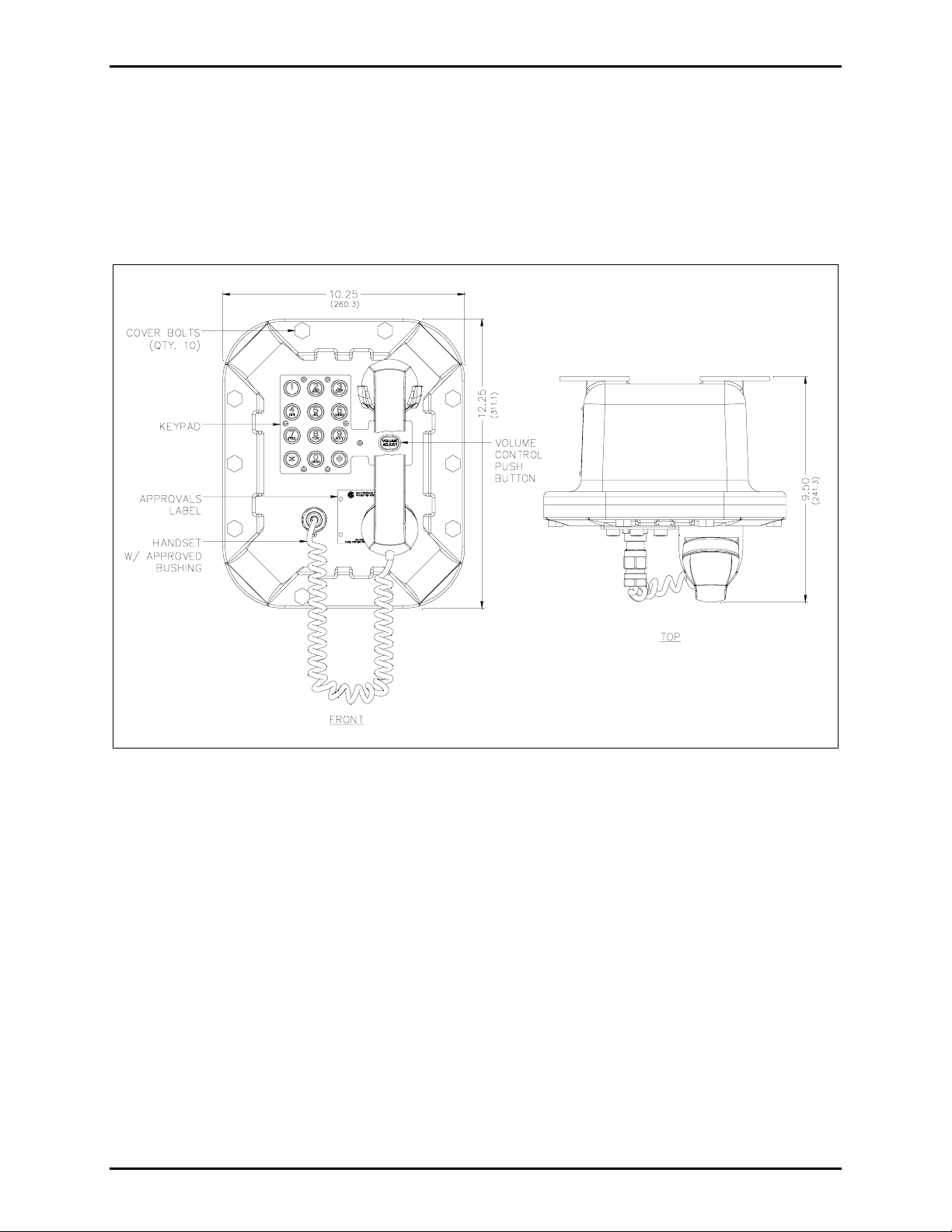
Models 352-001 and 352-002 each contain a handset with approved cable gland, standard keypad, volume
control button, and applicable approval labeling. The handset rests on a cradle, which has a magnetic
reed switch to signal an off-hook condition. The enclosure is sealed with ten cover mounting bolts
located around the perimeter of the enclosure’s flange. See Figure 4.
Figure 4. Model 352 Series Division 1 Hazardous Area Telephone Outline
f:\standard ioms - current release\42004 instr. manuals\42004-454a.doc
12/11
Page 5

Pub. 42004-454A
Model 352-001, 352-002, 352-003, and 352-004 Division 1 Telephones Page: 5 of 13
For Models 352-003 and 352-004 with the headset option, the cradle and handset are replaced with a
removable headset and headset activation bracket.
Figure 5. Model 352 Series Headset Models
f:\standard ioms - current release\42004 instr. manuals\42004-454a.doc
12/11
Page 6

Pub. 42004-454A
Model 352-001, 352-002, 352-003, and 352-004 Division 1 Telephones Page: 6 of 13
Internal
With the exception of the ring relay (when fitted), all standard components are mounted to the rear of the
front cover. See Figure 6 for the parts layout.
Figure 6. Model 352 Series Division 1 Hazardous Area Telephone - Internal View
Ring Relay PCBA
The Ring Relay PCBA allows the telephone to activate an external beacon or sounder when the telephone
receives a call. When installed, the Ring Relay PCBA is connected to the main PCBA via a USOC
RJ11C modular connector cord. This allows the telephone input wiring to be connected directly to the
Ring Relay PCBA. The Ring Relay PCBA is located in the rear enclosure. See Figure 6 for mounting,
and steps 3 through 5 in the “Wiring” section.
f:\standard ioms - current release\42004 instr. manuals\42004-454a.doc
12/11
Page 7

Pub. 42004-454A
Model 352-001, 352-002, 352-003, and 352-004 Division 1 Telephones Page: 7 of 13
Wiring
WARNING
The front cover is not hinged to the rear enclosure. When the cover bolts are
removed, the cover must be adequately supported.
1. While supporting the front cover, remove the ten cover bolts on the enclosure flange. Pull the front
cover far enough away to expose the internal connections and disconnect any wiring between the
front cover and rear enclosure. Place the front cover aside.
2. Connect the incoming subscriber line or the telephone line suppressor (if applicable) to TB1 on the
main PCBA. If there is not a Ring Relay PCBA present, see Figure 7.
f:\standard ioms - current release\42004 instr. manuals\42004-454a.doc
12/11
Figure 7.
Page 8

Pub. 42004-454A
Model 352-001, 352-002, 352-003, and 352-004 Division 1 Telephones Page: 8 of 13
3. When a Ring Relay PCBA is present, connect the incoming subscriber line to the TB1 terminal block.
See Figure 8 and Figure 9.
Figure 8.
Figure 9.
4. Connect the external sounder or beacon to TB2, for activation with an incoming telephone call.
5. Reconnect the USOC RJ11C modular connector cord to the Ring Relay PCBA, from the main PCBA
on the front panel, before reattaching the front cover.
WARNING
Any external equipment connected to the Ring Relay PCBA must be rated for the
hazardous area where it will be located. Improper installation or equipment may cause a safety hazard
and consequent injury or property damage.
Volume Control Jumper Setting
The handset receiver volume control is factory set to default to its original setting (0 dB) when the
telephone is hung up. To save the volume control setting, jumper J4, which is factory set at positions 2
and 3, must be moved to positions 1 and 2. Refer to Figure 7 for the location of J4.
f:\standard ioms - current release\42004 instr. manuals\42004-454a.doc
12/11
Page 9

Pub. 42004-454A
Model 352-001, 352-002, 352-003, and 352-004 Division 1 Telephones Page: 9 of 13
Auxiliary Output
Each telephone includes one isolated solid state switch capable of switching a maximum of 48 V dc, 125
mA or 28 V
auxiliary output. Refer to Figure 10 for the location of TB2. This output remains energized for the
duration of a call.
ac, 80 mA
RMS
. TB2 (AUX OUT) on the main PCBA provides the connections for the
RMS
Figure 10.
Attach the Front Cover
After all adjustments have been completed, inspect and clean the machined flange joint surfaces of both
the cover and box. Surfaces must be smooth, free of nicks, scratches, dirt or any foreign particle build-up
that would prevent a proper seal. Surfaces must seat fully against each other to provide a proper
explosion-proof joint. Clean surfaces by wiping with a clean lint-free cloth.
Apply a light coat of Killark “LUBG” lubricant to flange surfaces and close the cover. Install and tighten
all cover bolts to 30 ft-lbs. Make certain no cover bolts are omitted. Use only those bolts supplied with
the enclosure.
OTE: Refer to the Killark Installation, Operation, and Maintenance Data Sheet enclosed with the unit
N
for additional enclosure information.
f:\standard ioms - current release\42004 instr. manuals\42004-454a.doc
12/11
Page 10

Pub. 42004-454A
Model 352-001, 352-002, 352-003, and 352-004 Division 1 Telephones Page: 10 of 13
Operation
Models 352-001 and 352-002 Handset Operation
1. Lift the handset to place a call.
2. The handset receiver volume located on the front cover keypad, can be adjusted to the desired level
by pressing the volume control push button.
OTE: Pressing the volume control push button increases the volume in 3-dB increments. The
N
volume starts at 0 dB and increases to a maximum volume of 18 dB. Pressing the volume control
push button a seventh time will return the volume to 0 dB.
3. Dial the desired number.
4. After completion of the call, place the handset on-hook.
f:\standard ioms - current release\42004 instr. manuals\42004-454a.doc
12/11
Figure 11.
Page 11

Pub. 42004-454A
Model 352-001, 352-002, 352-003, and 352-004 Division 1 Telephones Page: 11 of 13
Models 352-003 and 352-004 Headset Operation
1. To connect the headset, plug it into the flexible plug on the front of the telephone by removing the
sealing cap from the receptacle, aligning the connector pins, and screwing the two ends together.
Figure 12.
2. To place a call, remove the headset from the headset activation bracket and flip the headset bracket
forward to its preset position. See Figure 12.
3. The handset receiver volume control, which is located on the front cover keypad, can be adjusted to
the desired level by pressing the volume control push button.
N
OTE: Pressing the volume control push button increases the volume in 3-dB increments. The
volume starts at 0 dB and increases to a maximum volume of 18 dB. Pressing the volume control
push button a seventh time will return the volume to 0 dB.
4. Dial the desired number.
f:\standard ioms - current release\42004 instr. manuals\42004-454a.doc
12/11
Page 12

Pub. 42004-454A
Model 352-001, 352-002, 352-003, and 352-004 Division 1 Telephones Page: 12 of 13
5. Flip the headset activation bracket to its vertical preset position to hang up. If applicable, place the
headset on the bracket after the completion of the call. Otherwise, disconnect the flexible receptacle
and plug by unscrewing the two ends, and pulling them apart. When disconnected, reattach the
sealing cap to the end of the receptacle. See Figure 13.
Figure 13.
Maintenance
Service
If your telephone requires depot service, contact your Regional Service Center for a return authorization
number (RA#). Equipment should be shipped prepaid to GAI-Tronics with a return authorization number
and a purchase order number. If the equipment is under warranty, repairs will be made without charge.
Please include a written explanation of all defects to assist our technicians in their troubleshooting efforts.
Call 800-492-1212 inside the USA or 610-777-1374 outside the USA for help identifying the Regional
Service Center closest to you.
f:\standard ioms - current release\42004 instr. manuals\42004-454a.doc
12/11
Page 13

Pub. 42004-454A
Model 352-001, 352-002, 352-003, and 352-004 Division 1 Telephones Page: 13 of 13
Specification s
Electrical (Typical)
Frequency response.................................................................................................................. 300–3,000 Hz
Inter-digit pause.................................................................................................................................. 100 ms
Minimum loop current........................................................................................................................ 20 mA
Signaling tone (DTMF).............................................................................................. 100 ms Tone Duration
Supervisory dc current ................................................................ Minimum 20 mA dc; maximum 60 mA dc
Supervisory dc voltage........................................................................... 24–60 V dc (not polarity sensitive)
Network interface.......................................................................................................................... Loop Start
Auxiliary output (isolated solid state switch) ................................................................. 48 V dc @ 125 mA
28 V
Ring Relay PCBA output mechanical relay contact ............................................................. 250 V ac @ 5A
30 V dc @ 5A
Network signaling............................................................................................................................... DTMF
Ringer Equivalence Number (REN) with
REN without
Ringer Relay PCBA .......................................................................................... 1.0A/1.3B
Ringer Relay PCBA............................................................. 3.1A
ac @ 80 mA
RMS
RMS
Environmental
Operating temperature ........................................................................ −40º F to +140º F (−40º C to +60º C)
Humidity ...................................................................................................................... 90% non-condensing
Mechanical
Enclosure .............................................................................. Cast aluminum with aluminized lacquer paint
Handset Cord .......................................................“G” style handset/PVC 6-foot extended length (standard)
Connections................................................................................ Internal screw-type barrier terminal blocks
Dimensions, Outside............................... 10.25 W × 12.25 H × 9.50 D inches (260.3 × 311.1 × 241.3 mm)
Mounting.................................................. Wall or column, four 3/8-inch (10 mm) mounting feet with slots
Shipping weight ................................................................................................................ 30.0 lbs. (13.6 kg)
Net weight......................................................................................................................... 28.0 lbs. (12.7 kg)
Approvals
NRTL listed ......................................................Hazardous locations Class I, Division 1, Groups B, C, & D
(USA and Canada) Class II, Division 1, Groups F & G
Class III, Division 1
T6 – Gas
T4A – Dust
User Instructions (USA)
This equipment has been tested and found to comply with the limits for a Class A digital device, pursuant to part 15 of the FCC
Rules. These limits are designed to provide reasonable protection against harmful interference when the equipment is operated in
a commercial environment. This equipment generates, uses, and can radiate radio frequency energy and, if not installed and used
in accordance with the instruction manual, may cause harmful interference to radio communications. Operation of this
equipment in a residential area is likely to cause harmful interference in which case the user will be required to correct the
interference at his own expense.
f:\standard ioms - current release\42004 instr. manuals\42004-454a.doc
12/11
Page 14

Warranty
Equipment. GAI-Tronics warrants for a period of one (1) year from the date of shipment, that any
GAI-Tronics equipment supplied hereunder shall be free of defects in material and workmanship, shall
comply with the then-current product specifications and product literature, and if applicable, shall be fit
for the purpose specified in the agreed-upon quotation or proposal document. If (a) Seller’s goods prove
to be defective in workmanship and/or material under normal and proper usage, or unfit for the purpose
specified and agreed upon, and (b) Buyer’s claim is made within the warranty period set forth above,
Buyer may return such goods to GAI-Tronics’ nearest depot repair facility, freight prepaid, at which time
they will be repaired or replaced, at Seller’s option, without charge to Buyer. Repair or replacement shall
be Buyer’s sole and exclusive remedy. The warranty period on any repaired or replacement equipment
shall be the greater of the ninety (90) day repair warranty or one (1) year from the date the original
equipment was shipped. In no event shall GAI-Tronics warranty obligations with respect to equipment
exceed 100% of the total cost of the equipment supplied hereunder. Buyer may also be entitled to the
manufacturer’s warranty on any third-party goods supplied by GAI-Tronics hereunder. The applicability
of any such third-party warranty will be determined by GAI-Tronics.
Services. Any services GAI-Tronics provides hereunder, whether directly or through subcontractors,
shall be performed in accordance with the standard of care with which such services are normally
provided in the industry. If the services fail to meet the applicable industry standard, GAI-Tronics will
re-perform such services at no cost to buyer to correct said deficiency to Company's satisfaction provided
any and all issues are identified prior to the demobilization of the Contractor’s personnel from the work
site. Re-performance of services shall be Buyer’s sole and exclusive remedy, and in no event shall GAITronics warranty obligations with respect to services exceed 100% of the total cost of the services
provided hereunder.
Warranty Periods. Every claim by Buyer alleging a defect in the goods and/or services provided
hereunder shall be deemed waived unless such claim is made in writing within the applicable warranty
periods as set forth above. Provided, however, that if the defect complained of is latent and not
discoverable within the above warranty periods, every claim arising on account of such latent defect shall
be deemed waived unless it is made in writing within a reasonable time after such latent defect is or
should have been discovered by Buyer.
Limitations / Exclusions. The warranties herein shall not apply to, and GAI-Tronics shall not be
responsible for, any damage to the goods or failure of the services supplied hereunder, to the extent
caused by Buyer’s neglect, failure to follow operational and maintenance procedures provided with the
equipment, or the use of technicians not specifically authorized by GAI-Tronics to maintain or service the
equipment. THE WARRANTIES AND REMEDIES CONTAINED HEREIN ARE IN LIEU OF AND
EXCLUDE ALL OTHER WARRANTIES AND REMEDIES, WHETHER EXPRESS OR IMPLIED BY
OPERATION OF LAW OR OTHERWISE, INCLUDING ANY WARRANTIES OF
MERCHANTABILITY OR FITNESS FOR A PARTICULAR PURPOSE.
Return Policy
If the equipment requires service, contact your Regional Service Center for a return authorization number
(RA#). Equipment should be shipped prepaid to GAI-Tronics with a return authorization number and a
purchase order number. If the equipment is under warranty, repairs or a replacement will be made in
accordance with the warranty policy set forth above. Please include a written explanation of all defects to
assist our technicians in their troubleshooting efforts.
Call 800-492-1212 (inside the USA) or 610-777-1374 (outside the USA) for help identifying the
Regional Service Center closest to you.
(Rev. 10/06)
 Loading...