

Page 1

Pub. 42004-323C
GAI-TRONICS® CORPORATION
A HUBBELL COMPANY
Model 305-002
600-Ohm Line Balance Assembly
Confidential ity Notice
This manual is provided solely as an operational, installation, and maintenance guide and contains
sensitive business and technical information that is confidential and proprietary to GAI-Tronics.
GAI-Tronics retains all intellectual property and other rights in or to the information contained herein,
and such information may only be used in connection with the operation of your GAI-Tronics product or
system. This manual may not be disclosed in any form, in whole or in part, directly or indirectly, to any
third party.
General Information
The GAI-Tronics Model 305-002 Line Balance Assembly is designed to properly load both the page and
party line circuits of a GAI-Tronics 600-ohm Page/Party
assembly must be installed in each system. The line balance assembly may be used in single or multi (up
to five) party line systems.
®
communication system. One line balance
Installation
There are three primary considerations in determining the location of the line balance assembly:
1. It should be near the electrical center of the system.
2. It should be adjacent to an indoor station in a relatively quiet area.
3. It should be no more than 26,400 feet (5 miles or 8 km) from the most distant station, when used with
GAI-Tronics’ standard cable. For larger systems or when non-standard cable is to be used, please
contact a GAI-Tronics representative for further information.
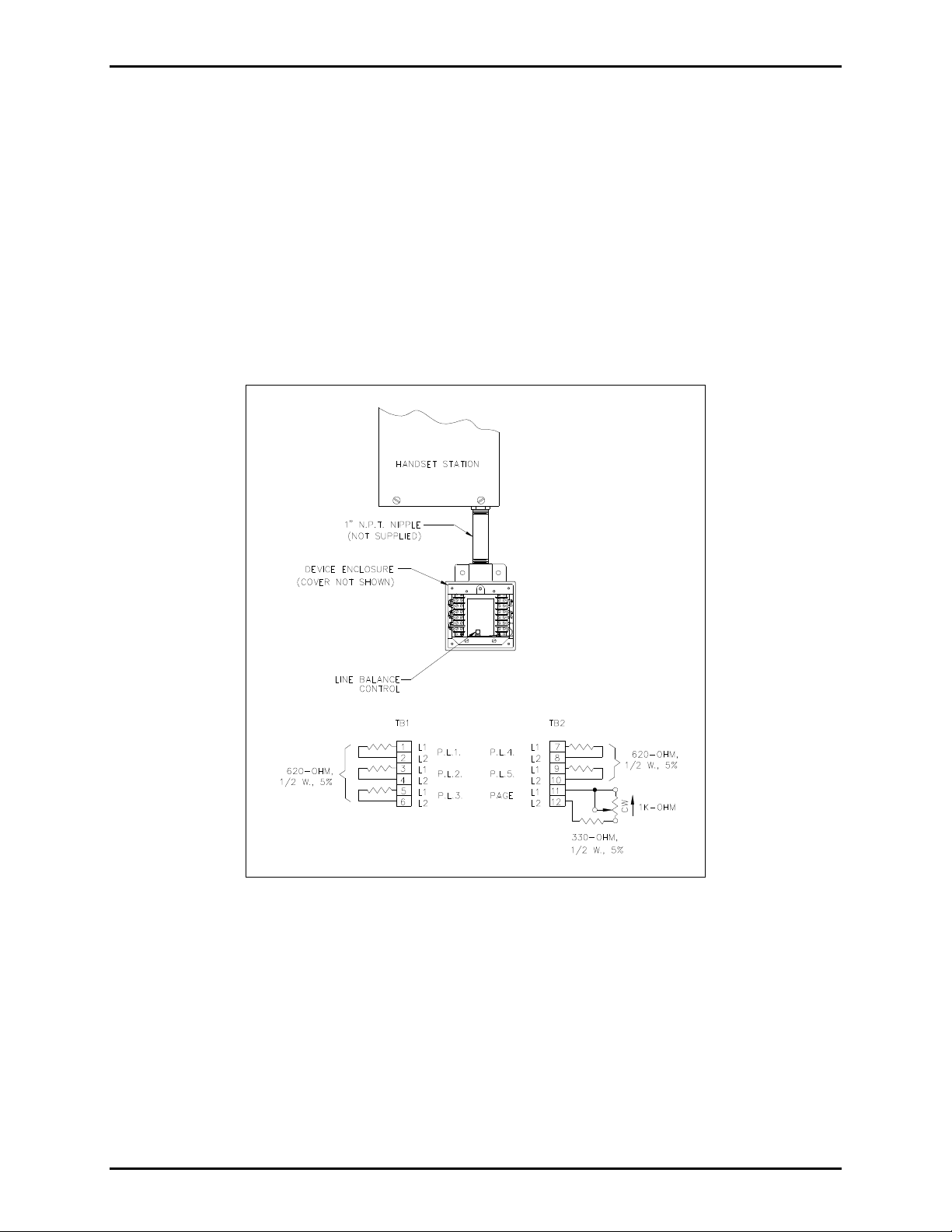
Mounting can be accomplished by either suspending the assembly by a 1-inch conduit nipple (not
supplied) from the bottom of an indoor wall station or by using the mounting ears located on the box.
Connect one twisted pair for the page circuit and a similar pair for each party line between the terminal
blocks of the line balance assembly and the associated indoor wall station.
Adjustment
To set the control for proper page circuit loading and to minimize the receiver sidetone, complete the
steps listed below. Sidetone is the amount of signal returned from the microphone to the receiver element
of the handset, i.e., how loudly the user hears his or her own voice. This adjustment needs to be made
during the initial installation of the system. However, if more than ten handset stations or speaker
amplifiers are added or deleted in the system at any time, readjust the page circuit loading.
GAI-Tronics Corporation 400 E. Wyomissing Ave. Mohnton, PA 19540 USA
610-777-1374 800-492-1212 Fax: 610-796-5954
V
ISIT WWW.GAI-TRONICS.COM FOR PRODUCT LITERATURE AND MANUALS
Page 2
Pub. 42004-323C
Model 305-002 600-Ohm Line Balance Assembly Page 2 of 2
1. Remove the line balance assembly cover to expose the line balance control.
2. Lift the handset from the adjacent station and press the P
AGE button.
3. Blow steadily into the handset microphone and adjust the control to minimize receiver sidetone.
4. After final adjustment, replace the cover and secure it with four mounting screws.
Each amplifier has a paging speaker volume control, accessible from the front panel with a screwdriver.
It is concealed behind the metal nameplate. To access the control, loosen (do not remove) the two
nameplate screws and pivot the nameplate around the left screw. This control is preset at the factory for a
moderate 4-watt output to the connected speaker.
For more detailed system installation information, please refer to GAI-Tronics Pub. 42004-324.
Figure 1. 305-002 Terminal Connections
Specification s
Terminations ............................ Barrier-type terminal blocks for field wiring to page and party line circuits
Mounting ....................................Mounting lugs or support by 1-inch NPT pipe nipple from handset station
Enclosure ................................... Cast aluminum two-gang outlet box with cast, dust-tight aluminum cover
Control ................................................................ Rheostat adjustment control provided for page line circuit
Finish .............................................................................................................................. Aluminum or epoxy
Dimensions .................................................... 5.30 H 4.60 W 2.25 D inches (134.6 116.8 57.2 mm)
Shipping weight ........................................................................................................................ 2 lbs. (0.9 kg)
f:\standard ioms - current release\42004 instr. man uals\42004-323c.doc
04/13
Page 3

Warranty
Equipment. GAI-Tronics warrants for a period of one (1) year from the date of shipment, that any
GAI-Tronics equipment supplied hereunder shall be free of defects in material and workmanship, shall
comply with the then-current product specifications and product literature, and if applicable, shall be fit
for the purpose specified in the agreed upon quotation or proposal document. If (a) Seller’s goods prove
to be defective in workmanship and/or material under normal and proper usage, or unfit for the purpose
specified and agreed upon, and (b) Buyer’s claim is made within the warranty period set forth above,
Buyer may return such goods to GAI-Tronics nearest depot repair facility, freight prepaid, at which time
they will be repaired or replaced, at Seller’s option, without charge to Buyer. Repair or replacement shall
be Buyer’s sole and exclusive remedy. The warranty period on any repaired or replacement equipment
shall be the greater of the ninety (90) day repair warranty or one (1) year from the date the original
equipment was shipped. In no event shall GAI-Tronics warranty obligations with respect to equipment
exceed 100% of the total cost of the equipment supplied hereunder. Buyer may also be entitled to the
manufacturer’s warranty on any third-party goods supplied by GAI-Tronics hereunder. The applicability
of any such third-party warranty will be determined by GAI-Tronics.
Services. Any services GAI-Tronics provides hereunder, whether directly or through subcontractors,
shall be performed in accordance with the standard of care with which such services are normally
provided in the industry. If the services fail to meet the applicable industry standard, GAI-Tronics will reperform such services at no cost to buyer to correct said deficiency to Company's satisfaction provided
any and all issues are identified prior to the demobilization of the Contractor's personnel from the work
site. Re-performance of services shall be Buyer's sole and exclusive remedy, and in no event shall GAITronics warranty obligations with respect to services exceed 100% of the total cost of the services
provided hereunder.
Warranty Periods. Every claim by Buyer alleging a defect in the goods and/or services provided
hereunder shall be deemed waived unless such claim is made in writing within the applicable warranty
periods as set forth above. Provided, however, that if the defect complained of is latent and not
discoverable within the above warranty periods, every claim arising on account of such latent defect shall
be deemed waived unless it is made in writing within a reasonable time after such latent defect is or
should have been discovered by Buyer.
Limitations / Exclusions. The warranties herein shall not apply to, and GAI-Tronics shall not be
responsible for, any damage to the goods or failure of the services supplied hereunder, to the extent
caused by Buyer’s neglect, failure to follow operational and maintenance procedures provided with the
equipment, or the use of technicians not specifically authorized by GAI-Tronics to maintain or service the
equipment. THE WARRANTIES AND REMEDIES CONTAINED HEREIN ARE IN LIEU OF AND
EXCLUDE ALL OTHER WARRANTIES AND REMEDIES, WHETHER EXPRESS OR IMPLIED BY
OPERATION OF LAW OR OTHERWISE, INCLUDING ANY WARRANTIES OF
MERCHANTABILITY OR FITNESS FOR A PARTICULAR PURPOSE.
Return Policy
If the equipment requires service, contact your Regional Service Center for a return authorization number
(RA#). Equipment should be shipped prepaid to GAI-Tronics with a return authorization number and a
purchase order number. If the equipment is under warranty, repairs or a replacement will be made in
accordance with the warranty policy set forth above. Please include a written explanation of all defects to
assist our technicians in their troubleshooting efforts.
Call 800-492-1212 (inside the USA) or 610-777-1374 (outside the USA) for help identifying the
Regional Service Center closest to you.
(Rev. 10/06)
 Loading...