

Page 1

Pub. 42004-470E
GAI-TRONICS® CORPORATION
A HUBBELL COMPANY
VoIP Clean Phone® Telephones
T ABLE OF C ONTENTS
Confidentiality Notice .....................................................................................................................3
Product Overview ............................................................................................................................3
Models ...................................................................................................................................................... 4
System Requirements and Limitations ................................................................................................. 4
Tips for VoIP Subscribers ...................................................................................................................... 4
Features and Functions .......................................................................................................................... 5
Operation .........................................................................................................................................5
®
Placing an Autodial Call from a VoIP Clean Phone
Placing a General Telephone Call ......................................................................................................... 5
Receiving a Call ....................................................................................................................................... 5
Multicast Broadcast ................................................................................................................................ 6
.......................................................................... 5
Monitoring and Reporting ..................................................................................................................... 6
Installation ......................................................................................................................................7
General Information ............................................................................................................................... 7
Safety Guidelines ..................................................................................................................................... 7
Station Placement .................................................................................................................................... 7
Model 295-702F ....................................................................................................................................... 8
Model 295-702W ................................................................................................................................... 12
Setup ..............................................................................................................................................14
Field Wire Installation .......................................................................................................................... 14
Power .................................................................................................................................................................. 14
Network .............................................................................................................................................................. 15
I/O ....................................................................................................................................................................... 16
Recommended Cabling ....................................................................................................................................... 17
VoIP Telephone Input Contacts .......................................................................................................... 17
VoIP Telephone Output Contacts ....................................................................................................... 17
Status Indication ................................................................................................................................... 17
Power .................................................................................................................................................................. 17
Heartbeat ............................................................................................................................................................. 17
EACT .................................................................................................................................................................. 17
Programming ................................................................................................................................18
VoIP PCBA Setup ................................................................................................................................. 18
GAI-Tronics Corporation 400 E. Wyomissing Ave. Mohnton, PA 19540 USA
610-777-1374 800-492-1212 Fax: 610-796-5954
V
ISIT WWW.GAI-TRONICS.COM FOR PRODUCT LITERATURE AND MANUALS
Page 2

PUB. 42004-470E
V
OIP CLEAN PHONE® TELEPHONES PAGE ii of 22
VoIP PCBA Initial Network Configuration ........................................................................................................ 18
Maintenance ..................................................................................................................................19
General Information ............................................................................................................................. 19
Service .................................................................................................................................................... 19
Troubleshooting .................................................................................................................................... 20
Specifications ................................................................................................................................21
Replacement Parts and Accessories .................................................................................................... 22
GAI-Tronics Corporation 400 E. Wyomissing Ave. Mohnton, PA 19540 USA
610-777-1374 800-492-1212 Fax: 610-796-5954
V
ISIT WWW.GAI-TRONICS.COM FOR PRODUCT LITERATURE AND MANUALS
Page 3
Pub. 42004-470E
GAI-TRONICS® CORPORATION
A HUBBELL COMPANY
VoIP Clean Phone® Telephones
Confidential ity Notice
This manual is provided solely as an installation, operation, and maintenance guide and contains sensitive
business and technical information that is confidential and proprietary to GAI-Tronics. GAI-Tronics
retains all intellectual property and other rights in or to the information contained herein, and such
information may only be used in connection with the operation of your GAI-Tronics product or system.
This manual may not be disclosed in any form, in whole or in part, directly or indirectly, to any third party.
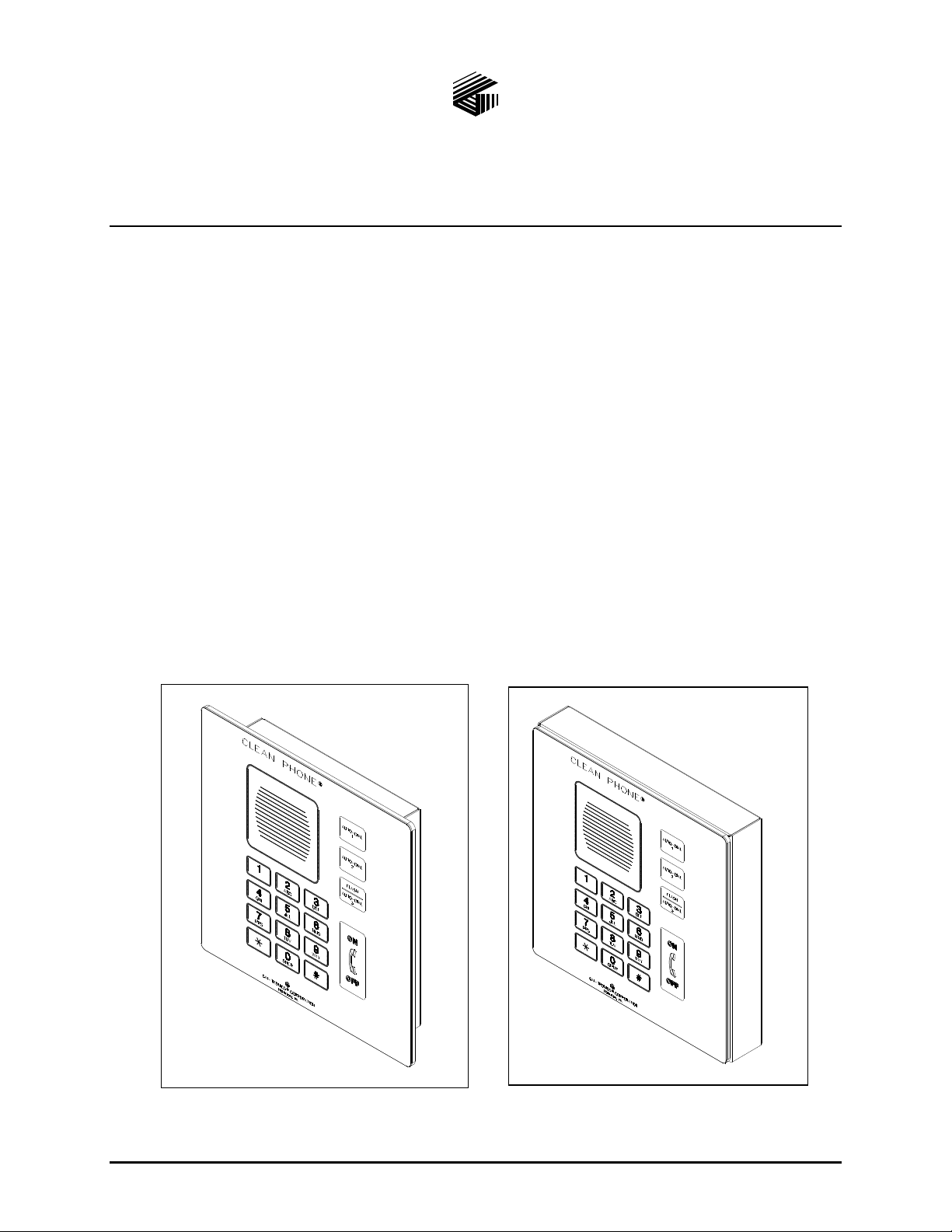
Product Overview
The GAI-Tronics Model 295-702F Flush-Mount and Model 295-702W Wall-Mount VoIP Clean Phone®
Telephones are designed for the exacting requirements of clean rooms. They are constructed of stainless
steel and have a completely smooth polyester front panel that will not trap particulate matter. Calls are
made by pressing one of the three auto-dial buttons or by using the fully functional keypad. The
oversized, clearly labeled buttons allow for easy operation with gloved hands.
The VoIP Clean Phone
These telephones will operate from Power-over-Ethernet or an external power source. The VoIP
telephones provide direct point-to-point communications between personnel throughout the facility over
the existing LAN.
®
Telephones are designed for connection to a 10/100 BaseT Ethernet network.
Figure 1. Model 295-702F
e:\standard ioms - current release\42004 instr. manuals\42004-470e.doc
07/14
Figure 2. Model 295-702W
Page 4

PUB. 42004-470E
V
OIP CLEAN PHONE® TELEPHONES PAGE 4 of 22
Models
The following VoIP Clean Phone® Telephones are detailed in this manual:
Table 1. Model Chart
Model Description
295-702W
Surface-Mount VoIP Telephone including a stainless steel front panel with polyester
overlay, three autodial buttons, hookswitch push button, off-hook indicator, keypad, and
stainless steel surface-mount enclosure.
295-702F
Flush-Mount VoIP Telephone including stainless steel front panel with polyester overlay;
three autodial buttons, hookswitch push button, off-hook indicator, keypad, and stainless
steel mounting bracket.
System Requirements and Limitations
The VoIP Telephones require Power-over-Ethernet or a local 24–48 V dc power source for operation.
Two VoIP telephones can be connected in a peer-to-peer configuration without the need for a LAN.
However, a 10/100 BaseT Ethernet with SIP Server is required for systems containing three or more VoIP
Telephones. Conferences are limited by the customer’s LAN media capabilities and the services
available at each end point.
In addition to direct point-to-point dialing (peer-to-peer), directly or via a SIP server, each telephone is
capable of receiving a Multicast broadcast. Multicast allows a single audio stream to be sent to multiple
end points simultaneously, to achieve multi-point paging or Public Address functionality over IP.
Multicast requires the use of a SIP server that specifically supports Multicast functionality and each
telephone must be configured (enabled) to receive Multicast packets.
Tips for VoIP Subscribers
If you have or are thinking of subscribing to an interconnected VoIP service, you should:
Provide your accurate physical address to your interconnected VoIP service provider to ensure that
emergency services can quickly be dispatched to your location.
Be familiar with your VoIP service provider’s procedures for updating your address, and promptly
update address information in the event of a change.
Have a clear understanding of any limitations of your 911 service.
If your power is out or your internet connection is down, be aware that your VoIP service may not
work. Consider installing a backup power supply, maintaining a traditional telephone line, or having
a wireless telephone as a backup.
If you have questions about interconnected VoIP and 911 or about VoIP in general, see
http://www.fcc.gov/cgb/consumerfacts/voip.html.
e:\standard ioms - current release\42004 instr. manuals\42004-470e.doc
02/15
Page 5

PUB. 42004-470E
V
OIP CLEAN PHONE® TELEPHONES PAGE 5 of 22
Features and Functions
The Clean Phone® Telephone’s voice-over-internet protocol (VoIP) include the following features:
SIP compatible (RFC3261)
Automatic call divert (memory list)
Real-time alarm reporting via email, syslog, or TMA software
Configurable via web page, serial link or download
Four auxiliary inputs; two volt-free contact outputs
Multicast capability, up to eight addresses
Operation
Placing an Autodial Call from a VoIP Cle an Phone®
To place an autodial call:
1. Press the desired autodial
2. When the call is connected, the hookswitch indicator will light.
3. The call is terminated by the following: pressing the ON/OFF push button, or the receiving caller
hanging up, or the defined timeout of the call duration, or via the SIP Server.
push button to place an immediate call to a preprogrammed number.
Placing a General Telephone Call
To place a general telephone call:
1. Press the ON/OFF push button.
2. Wait for the dial tone.
3. Use the keypad to dial the desired number.
4. When the call is connected, the “off-hook” indicator will light.
5. The call is terminated by one of the following methods: pressing the ON/OFF push button, the
receiving caller hanging up, call duration timeout, or via the SIP Server.
Receiving a Call
When a VoIP Clean Phone® is called, the unit automatically goes off-hook (auto-answer) and a
conversation can take place.
e:\standard ioms - current release\42004 instr. manuals\42004-470e.doc
02/15
Page 6

PUB. 42004-470E
V
OIP CLEAN PHONE® TELEPHONES PAGE 6 of 22
Multicast Broadcast
When making a Multicast call, the SIP server will send a paging request to a specific IP address and
expect multiple telephones to accept and play the subsequent audio. GAI-Tronics VoIP telephones can be
programmed for up to eight Multicast addresses to permit the receipt of Multicast broadcasts from
different sources or to enable zoning of broadcasts. Each Multicast address can be assigned a priority (via
programming) to define which can override which. A telephone with Multicast enabled can still make
and receive normal calls (peer-to-peer or SIP server). Normal calls can be assigned a priority level,
defining whether calls can override Multicasts or vice versa.
Monitoring and Reporting
Each telephone can recognize and generate several hardware and configuration fault condition alarms.
These alarms can be signaled to a remote site using three methods:
Syslog output over TCP
SMTP mail message
Telephone Management Application (TMA) software (purchased separately)
Available alarms are:
Handset integrity loop (if applicable)
Configuration error
Cold reset (power cycle)
Warm reset (internal command)
Keypad error (if applicable)
Key hook (off hook status, if applicable)
Register fail
Audio Path Test (speaker/microphone test)
e:\standard ioms - current release\42004 instr. manuals\42004-470e.doc
02/15
Page 7

PUB. 42004-470E
V
OIP CLEAN PHONE® TELEPHONES PAGE 7 of 22
Installation
General Information
WARNING
This product can contain hazardous voltages. Always remove power to this
station and any associated equipment before beginning any installation.
CAUTION
Do not install this equipment in areas other than those indicated on the
approval standards listing in the “Specifications” section of this manual. Such installation may
cause a safety hazard and consequent injury or property damage.
Install equipment without modification and according to all applicable local and national electrical codes.
Consult the National Electrical Code (NFPA 70), Canadian Standards Association (CSA 22.1), and local
codes for specific requirements regarding your installation. Class 2 circuit wiring must be performed in
accordance with NEC 725.55.
NOTE: This equipment has been tested and found to comply with the limits for a Class A digital device, pursuant to
part 15 of the FCC Rules. These limits are designed to provide reasonable protection against harmful interference
when the equipment is operated in a commercial environment. This equipment generates, uses, and can radiate
radio frequency energy and, if not installed and used in accordance with the instruction manual, may cause harmful
interference to radio communications. Depending upon the wiring and features used on this device, additional
precautions may be necessary not to cause harmful interference. Operation of this equipment in a residential area is
likely to cause harmful interference in which case the user will be required to correct the interference at his own
expense.
Safety Guidelines
When installing any GAI-Tronics equipment, please adhere to the following guidelines to ensure the
safety of all personnel:
Do not install wiring during a lightning storm.
Electrostatic Discharge (ESD) Protection: Your VoIP telephone may have an earth ground terminal
provision. If so, ensure that it is connected to ground in accordance with all local safety regulations
and the National Electrical Code (NEC). Grounding has to be ensured for safe and stable
communications. Do not use long and coiled ground wires. Trim ground wires to the required
length. Use a star configuration whenever possible. Please note proper grounding does not eliminate
the need for lightning protection for the telephone or the telephone system. A Cat5 data line lightning
surge protector is recommended for telephones subject to any electrostatic discharge (e.g. lightning).
Do not install jacks in wet locations unless the jack is specifically designed for wet locations.
Station Placement
To prevent feedback problems in the system, volume settings and station placement must be taken into
consideration. Unpleasant feedback problems can be reduced by:
Pointing the telephone away from other telephones located nearby
Reducing volume levels
Feedback problems can be avoided by installing each VoIP Clean Phone
®
in a separate room and wall.
e:\standard ioms - current release\42004 instr. manuals\42004-470e.doc
02/15
Page 8

PUB. 42004-470E
V
OIP CLEAN PHONE® TELEPHONES PAGE 8 of 22
Model 295-702F
The mounting and wiring instructions are as follows:
1. Remove the front panel from the back bracket.
2. Refer to Figure 5 on page 10 for cut-out details. Use the cut-out dimensions as a guide to mark the
wall, and make the required cuts.
3. If using Power-over-Ethernet, without any optional inputs or
outputs, place the bushing around the Ethernet cable so that it is
located approximately 5 inches from the end of the cable. Snap
the bushing closed and insert into the double “D” hole in the
bottom of the back bracket. See Figure 3 and Figure 6.
4. If using local power or optional inputs or outputs, route the cables
through the “D” hole in the bottom of the back bracket. See
Figure 6.
5. Place the back bracket in the wall. Locate the mounting holes.
Figure 3. Bushing
Refer to Figure 6.
6. Drill holes in the lower right and upper left corners and secure the bracket with screws. Drill the rest
of the holes you intend to use, and secure the bracket with the remaining screws.
7. Plug in the Ethernet cable and connect other optional cables as shown in the “Field Wire Installation”
section on page 14.
8. Perform the initial programming of the telephone. Refer to the “Programming” section beginning on
page 18.
9. Take the front panel of the VoIP Clean Phone
®
and align it with four slots in the back bracket.
10. Press the panel in firmly and then push downward to seat the panel in the slots.
OTE: The Model 295-702F is designed for general wipe down cleaning and to prevent collection
N
(internally and externally) of particulate matter. Additional protection against moisture can be attained by
sealing between the outer edge of the telephone panel and the mounting surface with silicone or RTV.
Any sealing substance used must be verified to be compatible with cleaning solutions used.
e:\standard ioms - current release\42004 instr. manuals\42004-470e.doc
02/15
Page 9

PUB. 42004-470E
V
OIP CLEAN PHONE® TELEPHONES PAGE 9 of 22
Figure 4. Inside Front Panel
e:\standard ioms - current release\42004 instr. manuals\42004-470e.doc
02/15
Page 10

PUB. 42004-470E
V
OIP CLEAN PHONE® TELEPHONES PAGE 10 of 22
Figure 5. Wall Cut-out Dimensions for Model 295-702F
e:\standard ioms - current release\42004 instr. manuals\42004-470e.doc
02/15
Page 11

PUB. 42004-470E
V
OIP CLEAN PHONE® TELEPHONES PAGE 11 of 22
Figure 6. Back Box for Model 295-702F
Figure 7. Front Panel
e:\standard ioms - current release\42004 instr. manuals\42004-470e.doc
02/15
Page 12

PUB. 42004-470E
V
OIP CLEAN PHONE® TELEPHONES PAGE 12 of 22
Model 295-702W
The mounting and wiring instructions are as follows:
1. Remove the front panel from the back box.
2. If using Power-over-Ethernet, without any optional inputs or outputs, place the bushing around the
Ethernet cable so that it is located approximately 5 inches from the end of the cable. Snap the
bushing closed and insert into the double “D” hole in the back box. See Figure 3 and Figure 8.
3. If using local power or optional inputs or outputs, route the cables through the “D” hole in the bottom
of the back box. See Figure 3 and Figure 8.
4. Position the back box on the wall, making sure the box is level.
5. Using the back box as a template, drill holes in the lower right and upper left corners, and secure the
back box with the screws. Drill the rest of the holes you intend to use, and secure the box with the
remaining screws.
6. Plug in the Ethernet cable and connect other optional cables, as shown in the “Field Wire Installation”
section on page 14.
7. Perform the initial programming of the telephone. Refer to the “Programming” section beginning on
page 18.
®
8. Take the front panel of the Clean Phone
and align it with the four slots in the back box.
9. Press the panel in firmly, and then push downward to seat the panel in the slots.
OTE: The Model 295-702W is designed for general wipe down cleaning and to prevent collection
N
(internally and externally) of particulate matter.
e:\standard ioms - current release\42004 instr. manuals\42004-470e.doc
02/15
Page 13

PUB. 42004-470E
V
OIP CLEAN PHONE® TELEPHONES PAGE 13 of 22
Figure 8. Mounting the Model 295-702W
e:\standard ioms - current release\42004 instr. manuals\42004-470e.doc
02/15
Page 14

PUB. 42004-470E
V
OIP CLEAN PHONE® TELEPHONES PAGE 14 of 22
Setup
Field Wire Installation
After all the field wires are pulled through the rear enclosure, install all connections as indicated below.
Refer to Figure 9 for wiring details. Refer to Table 5 on page 17 for the recommended conductor sizes.
N
OTE: Consult the National Electrical Code (NFPA 70), Canadian Standards Association (CSA 22.1),
and local codes for the specific requirements regarding your installation. Install all equipment without
modification and according to the local and national codes. Class 2 circuit wiring must be performed in
accordance with NEC 725.55.
Power
Power-Over-Ethernet
Connect power to the system as indicated in your PoE equipment manual.
Local Power
When PoE is not available, a separate, isolated 24–48 V dc power supply is required. A removable
terminal block P5 has been provided for connection of local power to the telephone. Connect the positive
conductor to the (+) terminal and the negative conductor to the (−) terminal of P5. See Figure 9 for
wiring and for the location of P5.
Table 2. Power – P5
Pin Label Description
1 (+) Positive
2 (−) Negative
Ground
The enclosure must be connected to earth ground. Install a #6 ring lug on the ground conductor and
secure it with the ground terminal located on the rear of the front panel.
e:\standard ioms - current release\42004 instr. manuals\42004-470e.doc
02/15
Page 15

PUB. 42004-470E
V
OIP CLEAN PHONE® TELEPHONES PAGE 15 of 22
Network
Connect a Cat5 or Cat5e cable with an RJ45 connector between the Local Area Network (LAN) and the
VoIP PCBA.
Figure 9. VoIP Telephone PCB Assembly
e:\standard ioms - current release\42004 instr. manuals\42004-470e.doc
02/15
Page 16

PUB. 42004-470E
V
OIP CLEAN PHONE® TELEPHONES PAGE 16 of 22
I/O
Inputs
Four auxiliary inputs have been provided for customer use. Terminations for these inputs are provided on
terminal block P12.
Table 3. Auxiliary Inputs – P12
Pin Label Function
1 IN4 Input 4
2 COM Common
3 IN3 Input 3
4 COM Common
5 IN2 Input 2
6 COM Common
7 IN1 Input 1
8 COM Common
Outputs
Two outputs have been provided for customer use. Terminations for these outputs are provided on
connector P10.
Table 4. Output Contacts – P10
Pin Label Description
1 C1 Common Output 1
2 NO1 Normally Open Output 1
3 C2 Common Output 2
4 NO2 Normally Open Output 2
e:\standard ioms - current release\42004 instr. manuals\42004-470e.doc
02/15
Page 17

PUB. 42004-470E
V
OIP CLEAN PHONE® TELEPHONES PAGE 17 of 22
Recommended Cabling
Table 5. Recommended Cabling
Cable Use Size and Type
LAN Cat5 or Cat5e cable with an RJ45 connector
Power Two-conductor, No. 22 AWG is typical
Inputs Two-conductor, No. 22 AWG is typical
Output contacts Two-conductor, No. 18 AWG is typical
VoIP Telephone Input Contacts
Each VoIP Clean Phone® Telephone accepts four volt-free inputs. Refer to the “Specifications” section
of this manual for the input ratings.
The function of each input is configurable. Inputs can be configured for one of the following modes: On,
Off, or On/Off. The signals can also be inverted between active high (INVERT) or active low
(NORMAL). Activation of these inputs can be configured to update a SYSLOG or generate an email.
Please refer to Figure 9 on page 15 of this manual and the “Logic Settings” section of GTC Pub. 42004396, “VoIP Telephone Configuration Guide” for programming instructions for these inputs.
VoIP Telephone Output Contacts
Each VoIP Clean Phone® Telephone contains two voltage-free output contacts. Refer to the
“Specifications” section of this manual for the output ratings. Both outputs are single-pole, single-throw
contacts.
The function of each output is configurable. Outputs can be configured for one of the following modes:
On, Off, Pulse, Mute, Ring, Call, Connect, Hook, In Use, Ring Cadence, Ring Out, Page, Registered, or
Emergency. In some modes, the duration of the activation or on/off times can also be set. Please refer to
Figure 9 on page 15 of this manual and the “Logic Settings” section of GTC Pub. 42004-396, “VoIP
Telephone Configuration Guide” for programming instructions for these outputs.
Status Indication
Power
The Power LED located on the VoIP PCBA illuminates when power is applied to the telephone. Please
refer to Figure 9 on page 15 for location.
Heartbeat
The Heartbeat LED located on the VoIP PCBA will flash when the telephone is operational over the
LAN. Please refer to Figure 9 on page 15 for location.
EACT
The EACT LED located on the VoIP PCBA will turn ON when VoIP PCBA is connected to an Ethernet
device and flash when data is being transmitted. Please refer to Figure 9 on page 15 for location.
e:\standard ioms - current release\42004 instr. manuals\42004-470e.doc
02/15
Page 18

PUB. 42004-470E
V
OIP CLEAN PHONE® TELEPHONES PAGE 18 of 22
Programming
The installer should ensure that the network is configured to allow VoIP communications (using the SIP
protocol) between the desired locations before attempting to configure the GAI-Tronics VoIP Telephones.
The general sequence for set up of the VoIP Clean Phone
®
Telephone is as follows:
VoIP PCBA Setup
Verify the PC is connected to the same network as the VoIP telephone.
The easiest way to get started is to make a network connection to the unit and log on via a web browser.
The unit is initially set with a static IP address:
IP address 192.168.1.2
A user name and password will be requested. The initial factory settings are:
User Name user
Password password
Changing the user name and password is recommended. This security measure helps to prevent
unauthorized changes to the VoIP Telephone Interface’s configuration.
VoIP PCBA Initial Network Configuration
Each VoIP PCBA must be set up for the network prior to installation. Assign a local ID, domain, proxy,
and registrar.
Assign a host name The host name provides identification of the different VoIP PCBAs on the
network.
Test Verify that calls can be made successfully.
Maintain Monitor alarms. Set up auto-updates.
Refer to Pub. 42004-481 for programming instructions of these VoIP devices.
e:\standard ioms - current release\42004 instr. manuals\42004-470e.doc
02/15
Page 19

PUB. 42004-470E
V
OIP CLEAN PHONE® TELEPHONES PAGE 19 of 22
Maintenance
WARNING
This product can contain hazardous voltages. Always remove power to this
station prior to servicing.
General Information
1. Inspect and replace frayed or cracked wiring.
2. Secure/replace loose wires and terminal lugs.
3. Remove corrosion from terminals.
4. Inspect fuse F1 on the VoIP Carrier PCBA.
Service
If your VoIP Clean Phone® Telephone requires depot service, contact your Regional Service Center for a
return authorization number (RA#). Equipment should be shipped prepaid to GAI-Tronics with a return
authorization number and a purchase order number. If the equipment is under warranty, repairs will be
made without charge. Please include a written explanation of all defects to assist our technicians in their
troubleshooting efforts.
Call 800-492-1212 inside the USA or 610-777-1374 outside the USA for help identifying the Regional
Service Center closest to you.
e:\standard ioms - current release\42004 instr. manuals\42004-470e.doc
02/15
Page 20

PUB. 42004-470E
V
OIP CLEAN PHONE® TELEPHONES PAGE 20 of 22
Troubleshooting
Table 6. Troubleshooting Chart
Problem Possible Solution
Low volume If the volume is low, increase the volume level in the telephone’s
programming configuration.
High volume If the volume is high, decrease the volume level in the telephone’s
programming configuration.
Front panel push buttons
are not operational
Verify the push buttons are properly configured.
Verify power is applied to the unit.
Inputs not operational Check the input connections.
Verify the inputs are properly configured.
Outputs not operational Check the output connections.
Verify the outputs are properly configured.
Cannot make or receive
calls
Check the connection of the LAN cable.
Verify that power is applied to the unit.
Verify the LAN parameters have been configured properly.
Verify the telephone has been set up on the network.
No power indication Check the power connections.
If using PoE, check the operation of the PoE equipment.
e:\standard ioms - current release\42004 instr. manuals\42004-470e.doc
02/15
Page 21

PUB. 42004-470E
V
OIP CLEAN PHONE® TELEPHONES PAGE 21 of 22
Specification s
Power
Network power............................................................. Power-over-Ethernet, 802.3af compliant (via RJ45)
Local power requirements .............................................................................................. 24–48 V dc, 6 watts
Network ........................................................................... 10/100 BaseT Ethernet RJ45, Cat5 or Cat5e UTP
Static IP Provisioning or DHCP STUN client (NAT traversal)
Call control signaling ..................................................................... SIP (RFC3261 compliant) loose routing
Configuration .............................................................................................................. Embedded web server
Configuration file download
Direct serial connection
Password protection
Inputs
Keypad ........................................................................................................................................ 3 4 matrix
Push buttons ....................................................................... Three autodial and an off-hook indicator/switch
Configurable inputs (quantity = 4) ............................................................ Internal pull-up 3.3 V dc tolerant
Outputs
Output 1 .............................................................................................. 8 amps @ 30 V ac/dc (resistive load)
Output 2 .............................................................................................. 8 amps @ 30 V ac/dc (resistive load)
Indicators
External .................................................................................................................... Off-hook indicator light
Internal on VoIP PCBA ........................................................................... Power, Heartbeat, & EACT LEDs
Audio output ........................................................................ 85 dB SPL or greater @ 1.0 meters (@ 1 kHz)
Mechanical
Temperature range
Operating ........................................................................................ −4º F to +131º F (−20º C to +55º C)
Storage ............................................................................................. −40º F to 158º F (−40º C to +70º C)
Relative humidity .............................................................................................. Up to 95%, non-condensing
PCBA (printed circuit board assembly) ............................................................................. Conformal coated
Chemical Resis t ance
Clean Phone® graphic overlay is designed to withstand exposure to many chemicals. Please contact the
factory for questions pertaining to chemicals not listed below:
Ajax/Vim in solution Downey/Lenor1 Petroleum spirit1
Alkalicarbonate solution
Ammonia (<40%) Glycerin Potassium ferricyanide
Acetic Acid (50%) Glycol Potassium hydroxide (<30%)
Ariel powder in solution
1
Bleach
Hydrochloric acid (<36.7%) SBP 60/951
Castor oil Hydrogen Peroxide (25% solution) Sulfuric acid (<10%)
Caustic soda (<40%) Linseed Oil Tomato Ketchup
Cutting oil Methanol Trichloroacetic acid (<50%)
Cylohexanol Nitric Acid (<10%) White spirit
Diacetone alcohol Paraffin oil Windex
Diesel Persil powder in solution
1
Extremely faint glossing of the texture was noted.
1
Ethanol Phosphoric acid (<30%)
1
Gumption1 Pure turpentine
1
1
Wisk
e:\standard ioms - current release\42004 instr. manuals\42004-470e.doc
02/15
Page 22

PUB. 42004-470E
V
OIP CLEAN PHONE® TELEPHONES PAGE 22 of 22
The Clean Phone
Concentrated mineral acids High pressure steam at over 100º C Methylene chloride
Concentrated caustic solution Benzyl alcohol UV exposure
Dimethylformamide Tetrahydrofuran
®
graphic overlay is NOT resistant to the following:
Model 295-702F Clean Phone®
Construction ........................................................ Front panel: 8 mil polyester over 16-gauge stainless steel
Mounting bracket: 16-gauge stainless steel
Dimensions .................................................... Front panel: 12.00 W 12.00 H inches; (304.8 304.8 mm)
Mounting bracket: 10.75 W 10.88 H 1.75 D inches; (273.1 276.2 44.3 mm)
Model 295-702W Clean Phone®
Construction ........................................................ Front panel: 8 mil polyester over 16-gauge stainless steel
Back enclosure: 16-gauge stainless steel
Dimensions ..................................................... Front panel: 12.00 W 12.00 H inches (304.8 304.8 mm)
Back enclosure: 12.00 W 12.00 H 2.06 D inches (304.8 304.8 52.3 mm)
Shipping weight & dimensions ...................................................... 12.15 lbs., 17.00 17.00 11.00 inches
Approval Stan dards
Safety of Information Technology Equipment ..................................................................... UL/CSA 60950
Compliance to Standard ................................................................................................ FCC CRF 47 Part 15
Replacement Parts and Accessories
Part No. Description
12565-702 Carrier/VoIP PCBA Replacement Kit
12585-001 Speaker Assembly Replacement Kit
21245-003 Terminal Block Connector, 2-Position (External power)
21245-002 Terminal Block Connector, 4-Position (Outputs)
62317-208 Connector, 8-Point (Inputs)
40419-011 Optional Plug-in Power Supply, 120/240 V ac input,
24 V dc output
e:\standard ioms - current release\42004 instr. manuals\42004-470e.doc
02/15
Page 23

Warranty
Equipment. GAI-Tronics warrants for a period of one (1) year from the date of shipment, that any
GAI-Tronics equipment supplied hereunder shall be free of defects in material and workmanship, shall
comply with the then-current product specifications and product literature, and if applicable, shall be fit
for the purpose specified in the agreed-upon quotation or proposal document. If (a) Seller’s goods prove
to be defective in workmanship and/or material under normal and proper usage, or unfit for the purpose
specified and agreed upon, and (b) Buyer’s claim is made within the warranty period set forth above,
Buyer may return such goods to GAI-Tronics’ nearest depot repair facility, freight prepaid, at which time
they will be repaired or replaced, at Seller’s option, without charge to Buyer. Repair or replacement shall
be Buyer’s sole and exclusive remedy. The warranty period on any repaired or replacement equipment
shall be the greater of the ninety (90) day repair warranty or one (1) year from the date the original
equipment was shipped. In no event shall GAI-Tronics warranty obligations with respect to equipment
exceed 100% of the total cost of the equipment supplied hereunder. Buyer may also be entitled to the
manufacturer’s warranty on any third-party goods supplied by GAI-Tronics hereunder. The applicability
of any such third-party warranty will be determined by GAI-Tronics.
Services. Any services GAI-Tronics provides hereunder, whether directly or through subcontractors,
shall be performed in accordance with the standard of care with which such services are normally
provided in the industry. If the services fail to meet the applicable industry standard, GAI-Tronics will
re-perform such services at no cost to buyer to correct said deficiency to Company's satisfaction provided
any and all issues are identified prior to the demobilization of the Contractor’s personnel from the work
site. Re-performance of services shall be Buyer’s sole and exclusive remedy, and in no event shall GAITronics warranty obligations with respect to services exceed 100% of the total cost of the services
provided hereunder.
Warranty Periods. Every claim by Buyer alleging a defect in the goods and/or services provided
hereunder shall be deemed waived unless such claim is made in writing within the applicable warranty
periods as set forth above. Provided, however, that if the defect complained of is latent and not
discoverable within the above warranty periods, every claim arising on account of such latent defect shall
be deemed waived unless it is made in writing within a reasonable time after such latent defect is or
should have been discovered by Buyer.
Limitations / Exclusions. The warranties herein shall not apply to, and GAI-Tronics shall not be
responsible for, any damage to the goods or failure of the services supplied hereunder, to the extent
caused by Buyer’s neglect, failure to follow operational and maintenance procedures provided with the
equipment, or the use of technicians not specifically authorized by GAI-Tronics to maintain or service the
equipment. THE WARRANTIES AND REMEDIES CONTAINED HEREIN ARE IN LIEU OF AND
EXCLUDE ALL OTHER WARRANTIES AND REMEDIES, WHETHER EXPRESS OR IMPLIED BY
OPERATION OF LAW OR OTHERWISE, INCLUDING ANY WARRANTIES OF
MERCHANTABILITY OR FITNESS FOR A PARTICULAR PURPOSE.
Return Policy
If the equipment requires service, contact your Regional Service Center for a return authorization number
(RA#). Equipment should be shipped prepaid to GAI-Tronics with a return authorization number and a
purchase order number. If the equipment is under warranty, repairs or a replacement will be made in
accordance with the warranty policy set forth above. Please include a written explanation of all defects to
assist our technicians in their troubleshooting efforts.
Call 800-492-1212 (inside the USA) or 610-777-1374 (outside the USA) for help identifying the
Regional Service Center closest to you.
(Rev. 10/06)
 Loading...