

Page 1
Pub. 42004-416A
GAI-TRONICS® CORPORATION
A HUBBELL COMPANY
Model 234SBM
Stanchion Broa dcast Module
Confidentiality Notice
This manua l is provide d sole ly as an operatio nal, installation, and ma inte nance guide and conta ins
sensitive business and t e chnical informatio n tha t is confidentia l and pr opri et ary to GAI- Tronics.
GAI-Tronics retains all intellectual property and other rights in or to the information contained herein,
and such information may only be used in connection with the operation of your GAI-Tronics product or
system. This manu al may not be dis clos e d in any form, in whole or in pa rt, direct ly or i ndir ectly, to a ny
third pa r ty.
General Information
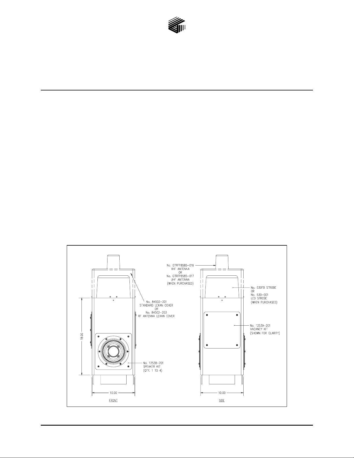
The Model 234SBM Stanchion Broadcast Module is designed to upgrade an existing Model 234
Stanchion for performing high-quality public address. The stanchion broadcast module broadcasts audio
that is received via the VHF or UHF module, or a 600-ohm line. Speaker configuration permits a 360º
broadcast coverage pattern.
The Model 84507-201 Stanchion Module measures 10 W × 10 D × 18 H inches, and is co nstr uct ed from
3/16-inch hot-rolled steel with a powder-coat finish.
Figure 1.
GAI-Tronics Corporation 400 E. Wyomissing Av e. Mohnton, PA 19540 USA
610-777-1374 800-492-1212 Fax: 610-796-5954
ISIT WWW.GAI-TRONICS.COM FOR PRODUCT LITERATURE AND MANUALS
V
Page 2

Pub. 42004-416A
Model 234SBM Stanc hion B r oadc ast M odule Page: 2 of 5
The following kits are available for use with the Model 234SBM:
• Model 10458-101 Paging Module consisting of 600-ohm line, power supply and terminal
connections.
• Model 10458-102 Paging Module consisting of a VHF radio module, power supply and terminal
connections.
• Model 10458-103 Paging Module consisting of a UHF radio module, power supply and terminal
connections.
• Model 12538-201 Speaker Kit, consisting of a speaker and wiring harness to connect to the Paging
Module.
• Model 12539-201 Vacancy Kit, consisting of a plate to cover any speaker openings not used.
• Model 12510-002 Small Access Panel Kit
• Model 12510-003 Large Access Panel Kit
• Model 12234-100 Dual-Band Antenna Kit consisting of a dual-band antenna, grounding plane, Lexan
cover with mounting hole, NMO antenna mount with 17-feet of cable and BNC connector
• Model 40201-010 Battery, 2.8 Ah
Installation
The following sections provide specific information for SBM. This manual also provides the
overall interconnection instruct ions for the stanchion and its ancillary equipment .
Safety Guidelines
When installing any GAI-Tronics equipment, please adhere to the following guidelines to ensure the
safety of all personnel:
• NEVER install telephone wiring during a lightning storm.
• NEVER install telephone jacks in wet locations unless the jack is specifically designed for wet
locations.
• USE CAUTION when installing or modifying telephone lines.
• DO NOT install antenna near electric power lines.
• ALWAYS remove power from the stanchion before removing the strobe.
f:\standard ioms - current releas e\ 42004 ins t r. manuals\42004-416a.doc
10/08
Page 3

Pub. 42004-416A
Model 234SBM Stanc hion B r oadc ast M odule Page: 3 of 5
Stanchion B roadcast Module Install ation
NOTE: For ease of installation, it is suggested that the Stanchion Broadcast Module be mounted to the
top of the existing 234 Series Stanchion before installing the speaker kits. This will reduce the weight of
the module and allow more areas to handle it.
1. Before installing the stanchion broadcast module, the existing strobe lens cover and strobe must be
first removed from the 234 Series Stanchion. To disassemble the lens cover, remove the four #10-32
screws from each side of the stanchion and lift off the lens cover.
2. Before disassembling the strobe, be sure to disconnect all the power and control wires from their
termination points. Remove the strobe by unscrewing it from the threaded nipple at the top of the
stanchion. Remove all wires from the nipple and place the assembly aside.
3. Before placing the stanchion broadcast module on the top of the 234 Series Stanchion, the existing
four #10-32 tapped holes must be drilled out to 0.313 inches. These holes will later be used to secure
the stanchion broadcas t module.
4. Place the stanchion broadcast module on top of the 234 Series Stanchion, sliding the module flanges
into the recessed top.
5. With the stanchion broadcast module now resting on the top of the 234 Series Stanchion, mark the
center of each of the four drilled 0.313 holes on the module flanges. Drill a 0.232 hole in each of
these four hole locations.
6. Use the supplied #1/4-20 stainless steel, self-threading screws to secure each flange. Be sure to
adequately drive and tighten these screws against the 234 Series Stanchion. Use all four screws to
properly secure the stanchion module. The four ¼-20 stainless steel, self-threading screws are
supplied with Model 12510-002 Small Access Panel Kit or Model 12510-003 Large Access Panel
Kit.
7. Follow the instructions for strobe installation contained on page 4 to secure the strobe before
installing the speaker assemblies. Follow the instructions in Pub. 42003-220 to install the antenna kit
before installing the speaker assemblies.
f:\standard ioms - current releas e\ 42004 ins t r. manuals\42004-416a.doc
10/08
Page 4

Pub. 42004-416A
Model 234SBM Stanc hion B r oadc ast M odule Page: 4 of 5
Strobe Installation
Before installing the antenna kit, mount the strobe according to the instructions below.
1. Insert the new strobe’s seven 15-foot wires through the stanchion module’s threaded nipple (center
hole), and through the threaded nipple on the existing stanchion. Allow the wires to extend to the
base of th e s tanchion. Se e Figure 2.
OTE: Wire lengths may need to be exten d ed prior to feeding t h em thr ough the thread ed nipp les.
N
Figure 2.
2. Screw the strobe onto the threaded nipple.
3. Separate the orange and violet wires necessary for the telephone connection, and extend those wires
through the stanchion cutout for the telephone; or extend the wires down to the opening for the access
panel in the rear of the stanchion body for connection to the paging module.
f:\standard ioms - current releas e\ 42004 ins t r. manuals\42004-416a.doc
10/08
Page 5

Pub. 42004-416A
Model 234SBM Stanc hion B r oadc ast M odule Page: 5 of 5
Model 12234-100 Dual -Band Antenna K it
Refer to Pub. 42003-220 for installation of the antenna kit (when applicable.)
Model 12538-201 Sp eaker Ki t & 12539-201 Va cancy Kit Instal lation
Refer to Pub. 42003-221 for installation of speaker and vacancy kits.
Model 40201-010 Ba ttery Installatio n
1. Batteries are shipped separately and are to be installed on site. Pay strict attention to battery polarity,
as reverse power will cause damage to internal components.
2. Make the wiring connection to the electronics module labeled 12V
battery cable. It is recommended that this be left disconnected from the module until you are ready to
power up the unit.
3. Attach the fast-on connectors to the batteries observing polarity (red+, black-) per drawing 73520.
4. Secure the batteries into L-bracket inside stanchion under phone opening.
N
OTE: If the stanchion body does not have any L-brackets, the battery must be set in the bottom of
the stanchion to the side, away from the conduit entries.
Refer to Pub. 42004-415, Model 10458-10x Electronics Paging Module Manual for interconnections and
installation.
BATTERY (red+, black-) with
Maintenance
Repairing Su rface Damage to P owder-Coa ted Stanchi ons
1. Carefully sand the damaged area to c lean a nd score the b ase met al, taking c are t o minimize a n y
additional damage to the surrounding powder coating.
2. Wipe the sanded area with a cleaning solvent, such as DuPont “PrepSol.” Allow the area to dry. This
type of product is available at auto parts stores. Denatured alcohol may also be used.
3. Prepare the bare metal surface for painting by treating it with phosphoric acid solution intended for
this purpose. Allow the area to dry.
4. Using a cotton swap or small brush, paint the prepared surface with an automotive enamel or oil base
polyu rethan e e name l such as Red Devil or R ustoleum. D O NOT USE Krylon-typ e pai nts. Ca refully
blend the repair enamel into the powd er coa t at the edges.
OTE: EXACT color matches may not be attainable.
N
Specification s
Dimensions ................................................................. 10 W × 10 D × 18 H inches (0.25 × 0.25 × 0.46 m)
Wall thickness.....................................................................................................3/16-inch hot rolled steel
Finish..............................................................................................................................Powdered coated
f:\standard ioms - current releas e\ 42004 ins t r. manuals\42004-416a.doc
10/08
Page 6

Warranty
Equipment. GAI-Tronics warrants for a period of one (1) year from the date of shipment, that any
GAI-Tronics equipment supplied hereunder shall be free of defects in material and workmanship, shall
comply with the then-current product specifications and product literature, and if applicable, shall be fit
for the purpose specified in the agreed-upon quotation or proposal document. If (a) Seller’s goods prove
to be defective in workmanship and/or material under normal and proper usage, or unfit for the purpose
specified and agreed upon, and (b) Buyer’s claim is made within the warranty period set forth above,
Buyer may return such goods to GAI-Tronics’ nearest depot repair facility, freight prepaid, at which time
they will be repaired or replaced, at Seller’s option, without charge to Buyer. Repair or replacement shall
be Buyer’s sole and exclusive remedy. The warranty period on any repaired or replacement equipment
shall be the greater of the ninety (90) day repair warranty or one (1) year from the date the original
equipment was shipped. In no event shall GAI-Tronics warranty obligations with respect to equipment
exceed 100% of the total cost of the equipment supplied hereunder. Buyer may also be entitled to the
manufacturer’s warranty on any third-party goods supplied by GAI-Tronics hereunder. The applicability
of any such third-party warranty will be determined by GAI-Tronics.
Services. Any services GAI-Tronics provides hereunder, whether directly or through subcontractors,
shall be performed in accordance with the standard of care with which such services are normally
provided in the industry. If the services fail to meet the applicable industry standard, GAI-Tronics will
re-perform such services at no cost to buyer to correct said deficiency to Company's satisfaction provided
any and all issues are identified prior to the demobilization of the Contractor’s personnel from the work
site. Re-performance of services shall be Buyer’s sole and exclusive remedy, and in no event shall GAITronics warranty obligations with respect to services exceed 100% of the total cost of the services
provided hereunder.
Warranty Periods. Every claim by Buyer alleging a defect in the goods and/or services provided
hereunder shall be deemed waived unless such claim is made in writing within the applicable warranty
periods as set forth above. Provided, however, that if the defect complained of is latent and not
discoverable within the above warranty periods, every claim arising on account of such latent defect shall
be deemed waived unless it is made in writing within a reasonable time after such latent defect is or
should have been discovered by Buyer.
Limitations / Exclusions. The warranties herein shall not apply to, and GAI-Tronics shall not be
responsible for, any damage to the goods or failure of the services supplied hereunder, to the extent
caused by Buyer’s neglect, failure to follow operational and maintenance procedures provided with the
equipment, or the use of technicians not specifically authorized by GAI-Tronics to maintain or service the
equipment. THE WARRANTIES AND REMEDIES CONTAINED HEREIN ARE IN LIEU OF AND
EXCLUDE ALL OTHER WARRANTIES AND REMEDIES, WHETHER EXPRESS OR IMPLIED BY
OPERATION OF LAW OR OTHERWISE, INCLUDING ANY WARRANTIES OF
MERCHANTABILITY OR FITNESS FOR A PARTICULAR PURPOSE.
Return Policy
If the equipment requires service, contact your Regional Service Center for a return authorization number
(RA#). Equipment should be shipped prepaid to GAI-Tronics with a return authorization number and a
purchase order number. If the equipment is under warranty, repairs or a replacement will be made in
accordance with the warranty policy set forth above. Please include a written explanation of all defects to
assist our technicians in their troubleshooting efforts.
Call 800-492-1212 (inside the USA) or 610-777-1374 (outside the USA) for help identifying the
Regional Service Center closest to you.
(Rev. 10/06)
 Loading...