

Page 1

Pub.: 42004-393B
GAI-TRONICS® CORPORATION
A HUBBELL COMPANY
Model 234L(x)-xxx
LITE Series Stanchion
TABLE OF C ONTENTS
Confidentiality Notice.................................................................................................................1
General Information..................................................................................................................1
Installation................................................................................................................................. 3
Unpacking.......................................................................................................................................... 3
Mounting Panel Pre-Wiring..............................................................................................................4
24 V DC Modifications.................................................................................................................................. 4
Installation of Model 203-003 Interior Lighting Kit......................................................................... 5
Stanchion Mounting..........................................................................................................................7
Installation Wiring ............................................................................................................................ 9
Telephone Installation.....................................................................................................................13
Final Assembly.................................................................................................................................15
Maintenance.............................................................................................................................16
Cleaning...................................................................................................................................................... 16
Decal Repair................................................................................................................................................ 16
Replacement Parts........................................................................................................................... 17
Specifications................................................................................................................. ..........18
GAI-Tronics Corporation P.O. Box 1060, Readi ng, PA 19607-1060 USA
610-777-1374 800-492-1212 Fax: 610-796-5954
ISIT WWW.GAI-TRONICS.COM FOR PRODUCT LITERATURE AND MANUALS
V
Page 2

Pub.: 42004-393B
GAI-TRONICS® CORPORATION
A HUBBELL COMPANY
Model 234L(x)-xxx
LITE Series Stanchion
Confidentiality Notice
This manual is provi ded so lely as a n opera tiona l, ins tallat i o n, and maintenance guide and conta ins
sensiti v e b usiness and te chni c al infor mation tha t is con f idential and proprieta ry to G AI-T ronics. G AITronics retains all intellectual property and other rights in or to the information contained herein, and
such informatio n may on ly be u sed in con nection with t he op erat ion of y our G AI - Tr onics p roduct or
system. This manual may not be di sclosed in any for m, in whol e or in part, directly or in directly, to any
third pa r ty.
General Information
GAI-Tronics Model 234L(x)-xxx LITE ( Lightweight Illuminated Telecommu nications Enclosure) Seri es
Stanchions are designed for use in commercial environments to house GAI-Tronics telephones. The
LITE Series Stanchions are designed for wall mounting, and are comprised of a front stanchion body and
rear mounting plate.
The LITE Series Stanchions are available in both ac and 12 V dc versions. The standard LITE Series
Stanchion body is made of a durable 3/16-inch nominal thickness acrylic sheet in safety yellow with black
ASSISTANCE graphics applied on each side. The 1/16-inch thick aluminum rear mounting plate is
powder coated gray for maximum durability. An additional eight stanchion colors and four graphics are
also available.
Two LED lights are mounted on the front of the stanchion. The LED locator light contains super bright
LEDs that are visible even in sunlight. The courtesy LED panel light provides nighttime illumination of
the telephone.
The blue beacon mounted on top of the stanchion provides a visual indication that the stanchion telephone
is in use. When used with the GAI-Tronics Series 297 and 298 Series Push-Button Phones, the blue
beacon energizes when the red push button is activated and will remain activated until the call is
terminated. When used with the GAI-Tronics Series 276 and 277 Handset Phones, the blue beacon
energizes when the handset is lifted from the cradle, and remains activated until the handset is hung up.
Refer to the Telephone Installation section on page 13.
GAI-Tronics Corporation P.O. Box 1060, Readi ng, PA 19607-1060 USA
610-777-1374 800-492-1212 Fax: 610-796-5954
ISIT WWW.GAI-TRONICS.COM FOR PRODUCT LITERATURE AND MANUALS
V
Page 3
Pub. 42004-393B
Model 234L(x)-xxx LITE Series Stanchion Page: 2 of 18
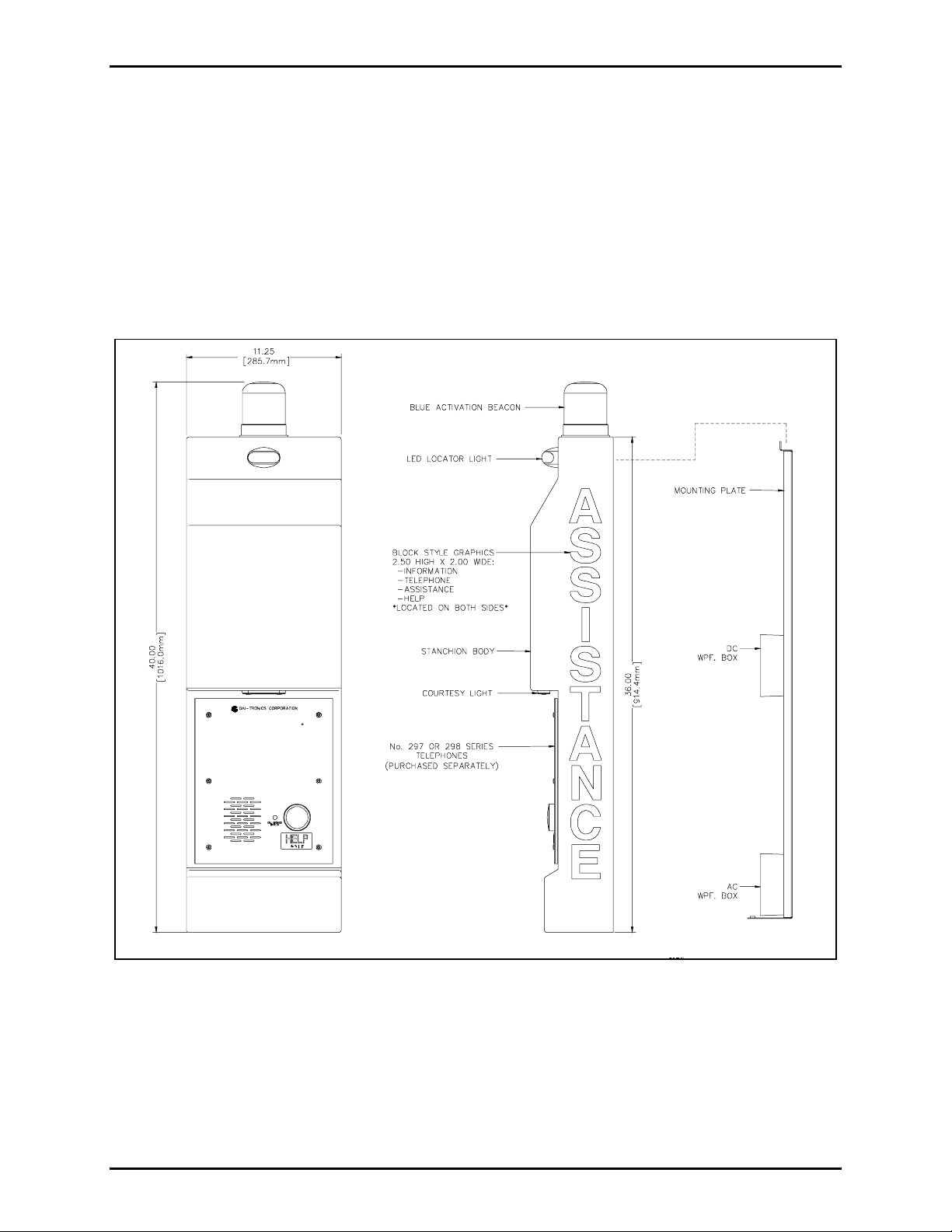
The stanchion rear mounting plate contains a weatherproof box that houses the activation relay PCBA and
a terminal block. The ac version is equipped with a second weatherproof box containing a switching
power supply for converting ac line voltage to 12 V dc power. Refer to Figure 1. All components
mounted to the exterior of the main stanchion body are powered by 12 V dc. Each LITE Series Stanchion
includes weatherproof entry bushings, weather-resistant cable, wire nuts, and connection hardware needed
for installation.
As an optional feature, most LITE Series Stanchions can be illuminated from inside the stanchion body
for maximum visibility. The Model 203-003 LED String Lighting Kit contains a 19-module LED string
designe d to be mounted within the LITE Seri es Stanchi on. Al l neces sary mounti ng hardware is in clud e d
with each stanchion. Refer to the Interior Lighting Kit section on page 5 for more information.
Figure 1. LITE Series Stanchion Outline
\\s_eng\gtc proddoc s \st andard iom s - current release\42004 instr. manuals \42004-393b.doc
03/07
Page 4

Pub. 42004-393B
Model 234L(x)-xxx LITE Series Stanchion Page: 3 of 18
Installation
Unpacking
The LITE Series Stanchion is shipped packaged in a single carton. GAI-Tronics 290 and 270 Series
Telephones, and the Model 203-003 Interior Lighting Kit are purchased separately and packed in separate
cartons . The LITE Series Stanchi on carton c onta ins t he following:
• Stanchion main body with mounted lights
• Rear mounting plate with weatherproof boxes and components
• Pa dde d mai l er cont a i ni ng :
— #6-32 Keps nuts 5 5
— #6-32 Flat head thread cutting screws 8 8
— #10-32 Tamper-resistant pan head screws 2 2
— #6 flat washers 5 5
— Wire nuts 12 12
— Cable ties 6 6
— Anchor mounts, cable tie 2 2
— Packaged weatherproof covers with gaskets 2 1
— Cable bushings 5 4
— Weather resistant cable 1 1
Quantities: AC 12 V DC
\\s_eng\gtc proddoc s \st andard iom s - current release\42004 instr. manuals \42004-393b.doc
03/07
Page 5
Pub. 42004-393B
Model 234L(x)-xxx LITE Series Stanchion Page: 4 of 18
Mounting Panel Pre-Wiring
For ease of installation, th e L I TE Series Sta nc hion can be p artially p re- wired on a horiz ontal sur f ace prior
to mounting. This minimizes the connections that must be made when the stanchion is attached to the
wall. It is also recommended that the appropriate telephone back box be mounted to the stanchion body
at this time. See Telephone Installation on page 11.
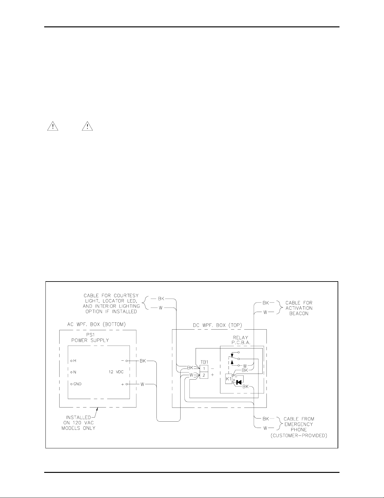
Make the rear mounting plate wiring connections between and within the weatherproof boxes. Connect
the wire leads for stanchion lights. Refer to the connection diagram in Figure 2 for components that can
be pre-wired.
NOTE
All connections must b e made in accordance w ith the National Electrical Code
(NEC) in the United S ta tes o r the Canadian El ectrical Codes (CEC) in Canada.
Additionally, if the Model 203-003 Interior Lighting Kit is to be installed, it should be done at the same
time. Refer to the Interior Lighting Kit section on page 5 for installation instructions.
Wire routing is exceptionally important if interior lighting is installed. Wires must be adequately bundled
and anchored so as not to cast shadows on the main stanchion body. Refer to Figure 3 for proper wire
routing a nd anchor ing.
24 V DC Modification s
GAI-Tronics 12 V dc LITE Series Stanchions are preset for 12 V dc power operation. For 24 V dc input
operation, modifications must be made to the stanchion. Modify the stanchion by removing the jumper
(labeled JMPR) located on the upper right side of the relay PCBA within the dc weatherproof box.
Additionally, the locator light must be replaced with a 24 V dc compatible version. Contact GAI-Tronics
Corporation to obtain a 24 V dc version of the locator light. Supply the stanchion with 24 V dc input
power.
Figure 2. LIT E S tanchion P re-w ired I nter nal Co nnectio ns
\\s_eng\gtc proddoc s \st andard iom s - current release\42004 instr. manuals \42004-393b.doc
03/07
Page 6

Pub. 42004-393B
Model 234L(x)-xxx LITE Series Stanchion Page: 5 of 18
Installa tion of Model 203-003 Int erior Lighting K it
Most LITE Seri es Stanchio n models can be illuminate d from the interior p roviding a glowing appear ance
for maximum visibility. This is especially effective at night or in low light areas such as parking garages.
The optional Model 203-003 Interior Lighting Kit for the LITE Series Stanchion contains a 19-module
LED string, with each module containing four super bright white LEDs. The string of LEDs is mounted
to the stanchion’s rear mounting plate. All LITE Series Stanchions include the necessary hardware for
attaching the LED string to the mounting plate.
OTE: The foll owing sta nchi on colors c annot be lit from the interior because the stanchion body
N
material is opaque:
234LN-xxx - Night Black (PLEXIGLAS 2025)
234LE-xxx - Earth Brown (PLEXIGLAS 2418)
234LU-xxx - Utility Gray (PLEXIGLAS 3001)
Begin installation of the Model 203-003 Interior Lighting Kit by placing the rear mounting plate on a
horizontal surface. Arrange the string of LEDs, without permanently attaching them, as shown in
Figure 3. Hook the mounting feet on the five mounting studs to insure proper layout and spacing of the
string. Untwist any modules as necessary. Permanently attach the LED modules to the panel as follows:
1. Place the five provided metallic spacer washers (provided with stanchion) on each mounting stud.
Beginning in the bottom left of the rear mounting plate, peel the transfer film off of the first LED
modu le and locate it u sing the protruding stud. R efer to F igur e 3 .
2. Move to the mounting stud on the top left corner and peel the transfer film off of the LED module
closest to it. Locate it us ing the protruding stud. Repe at this step for the top cent er, t op right, and
bottom right protruding studs. Do not peel the transfer film and attach the LED modules between the
studs.
3. Assemble the 6-32 nuts (provided with stanchion) to the studs with the LED modules on them.
Tighten the nuts snug against the modules. Do not over-tighten the nuts, as this will stress the selfadhesive tape on the modules.
4. Beginning in the bottom left of the panel, peel the transfer film from the remaining LED modules and
attach them. Align each module with the one below it and maintain consistent spacing between each
module. Repeat this step with all modules, working around the panel in a clockwise direction. If care
is taken, the modules will be consistently spaced when complete.
5. Finally, wire the module string into 12 V dc power. Refer to Figure 3 for the suggested wire layout
and connection points. If a separate 12 V dc power source is used, be sure to attach the white wire to
positive and black to negative.
\\s_eng\gtc proddoc s \st andard iom s - current release\42004 instr. manuals \42004-393b.doc
03/07
Page 7

Pub. 42004-393B
Model 234L(x)-xxx LITE Series Stanchion Page: 6 of 18
Figure 3. Basic Wir e Routing
\\s_eng\gtc proddoc s \st andard iom s - current release\42004 instr. manuals \42004-393b.doc
03/07
Page 8

Pub. 42004-393B
Model 234L(x)-xxx LITE Series Stanchion Page: 7 of 18
Stanchion Moun ting
The LI TE Seri es Stanchio n mountin g plate has four 5/16-inch diameter mounting holes for attaching th e
stanchion to the wall.
1. Fasten the mounting plate to a wall or flat surface that can support at least 25 pounds, using 1/4-inch
bolts and fender washers (customer supplied) for attachment. Refer to Figure 4 for mounting hole
dimensi ons a nd sugg e st e d mounting heig ht.
NOTE
It is the i nstaller’s re s ponsibility to mount the sta nchion at a height in
accordance w ith the American Disabilit ies Act (ADA) and any other applicable codes.
2. Determi ne the met hod o f ro uting the external power cable in to the stanchi on. The extern al pow er
cable can be routed to enter the stanchion through the bottom or the back of the mounting plate.
Refer to Figure 4.
3. The bottom of the mounting plate contains three locating holes for cable entry. Remove the bottom
weatherproof box before drilling. Drill out the ce nter hole with enough clea rance to a llow 1/2 NPT
conduit entry into the weatherproof box for power cable entry.
4. If entering through the back of the mounting plate, drill a hole with enough clearance to allow 1/2
NPT conduit entry into the weatherproof box. Remove the 1/2-inch conduit hole plug from the rear
of the weatherproof box to locate the drilled hole location.
5. The left or right hole at the bottom of the mounting plate can be drilled to allow wire entry for the
telephone PBX line.
\\s_eng\gtc proddoc s \st andard iom s - current release\42004 instr. manuals \42004-393b.doc
03/07
Page 9

Pub. 42004-393B
Model 234L(x)-xxx LITE Series Stanchion Page: 8 of 18
Figure 4. Mounting Detail
\\s_eng\gtc proddoc s \st andard iom s - current release\42004 instr. manuals \42004-393b.doc
03/07
Page 10

Pub. 42004-393B
Model 234L(x)-xxx LITE Series Stanchion Page: 9 of 18
Installa tion Wiring
NOTE
All connections must be made in accordance with the National Electrical Code (NEC)
in the United States or the Canadian Electrical Codes (CEC) in Canada. External power should not be
applied to the stanchion until all wiring has been completed. The NEC will require a minimum No. 18
AWG wire for the field wiring of the ac mains and an appropriate disconnect device shall be provided as
part of the building installation.
Figure 5. Connection Diagram
\\s_eng\gtc proddoc s \st andard iom s - current release\42004 instr. manuals \42004-393b.doc
03/07
Page 11

Pub. 42004-393B
Model 234L(x)-xxx LITE Series Stanchion Page: 10 of 18
1. After attaching the pre-wired mounting plate to the wall, make connections for the light components
on the main stanchion body. For ease of connection, and to maintain shorter wire lengths, position
the main stanchion body on a cart or temporary stand as close to the mounting plate as possible.
2. Connect the LED locator light and courtesy light wires to the proper 12 V dc power cable leads from
the weatherproof box. Connect the activation beacon wires to the relay cable leads from the
weat herp roof box. Refer to Figure 5 a nd Figure 6.
OTE 1: Final installation wiring is exceptionally important when the interior lighting kit is installed.
N
Wires must adequately bundled and anchored so as not to cast shadows on the main stanchion body. For
proper wire routing and cable tie anchoring refer to Figure 6.
OTE 2: Ensure that all wiring connections are securely twisted, capped with the supplied wire nuts, and
N
properly taped with electrical tape.
With the exception of connecting to a GAI-Tronics telephone output and customer-supplied incoming
power, all internal wiring connections should now be complete.
Figure 6. Installat ion Wirin g D iagram
\\s_eng\gtc proddoc s \st andard iom s - current release\42004 instr. manuals \42004-393b.doc
03/07
Page 12

Pub. 42004-393B
Model 234L(x)-xxx LITE Series Stanchion Page: 11 of 18
3. Connect the proper power source to the stanchion. For ac powered stanchions, power should be
routed to the ac weatherproof box located at the bottom of the stanchion. For 12 V dc powered
stanchions, the corresponding 12 V dc can be routed directly into the weatherproof box containing the
relay and terminal block. Attach the power input directly to the terminal block (positive = red or
white, negative = black). All cable entering or exiting the weatherproof boxes must be properly
sealed with the supplied Heyco bushings or properly sized conduit fittings. For 12 V dc stanchion
models, skip to step 6.
4. To attach the incoming ac power to the power switcher, remove the two screws holding the internal
mounting bracket. The switching power supply is attached to this bracket. Connect incoming ac
power to the corresponding connection point on the power switcher (H = black, N = white, ground
symbol = green). Refer to Figure 7.
Figure 7. Power Supply - Exploded View
\\s_eng\gtc proddoc s \st andard iom s - current release\42004 instr. manuals \42004-393b.doc
03/07
Page 13

Pub. 42004-393B
Model 234L(x)-xxx LITE Series Stanchion Page: 12 of 18
5. Reattach the internal mounting bracket. Route the incoming power wires through the access slot on
the bracket. Use the two screws that were removed previously to reattach the bracket.
6. Slide the stanchion body over the upper lip of mounting plate at an angle that allows the support bar
of the main body to slide into the top lip of the mounting plate. Rotate the main body parallel to the
support surface, allowing the bottom lip of the mounting plate to insert into the stanchion body. Refer
to Figure 8. Do not attach the bottom attachment screws until after telephone installation and final
test.
Figure 8. Assemble Stanchion
\\s_eng\gtc proddoc s \st andard iom s - current release\42004 instr. manuals \42004-393b.doc
03/07
Page 14

Pub. 42004-393B
Model 234L(x)-xxx LITE Series Stanchion Page: 13 of 18
T elephone Install ation
The following GAI-Tronics telephone models are compatible with the LITE Series Stanchions.
Pub. No. Telephone Model
Pub. 42004-352 Model 297-001 Flush-Mount Hands-free Phone
Pub. 42004-351 Model 297-003 S.M.A.R.T. Flush-Mount Hands-free Phone
Pub. 42004-352 Model 298-001 Flush-Mount Hands-free Phone with Keypad
Pub. 42004-351 Model 298-003 S.M.A.R.T. Flush-Mount Hands-free Phone with Keypad
Pub. 42004-350 Model 277-003 S.M.A.R.T. Flush-Mount Handset Autodial Phone
Pub. 42004-349 Model 276-003 S.M.A.R.T. Flush-Mount Handset Phone with Keypad
Pub. 42004-337 Model 276-001 Industrial Phone with Keypad
Pub. 42004-338 Model 277-001 Autodial Telephone
The telephones listed above must be weatherproofed before installation within a LITE Series Stanchion in
an unprotected outdoor environment. All stanchion components are housed in weatherproof boxes
(3R rating) or are completely sealed (IP 66 rating). Standard GAI-Tronics telephones do not have sealed
rear enclosures, and the stanchion body does not provide adequate protection. Weatherproofing can be
accomplished in two ways: by purchasing a sealed back box (Part No. 236-002) or by sealing the standard
GAI-Tronics back box.
OTE: Steps 1 through 4 should be performed prior to wiring the stanchion body components to the rear
N
mounting plate.
1. Separate the back box from the telephone front panel.
2. If installing in an unprotected outdoor area, a sealed telephone back box must be used. Part No.
236-002 sealed back box can be purchased, or the supplied standard back box enclosure can be
sealed.
3. To seal the standard back box, run a sufficient bead of silicon caulk on both the inside and outside of
the enclosure’s four corners and seams. Ensure that all gaps are sealed.
4. The standard back box has a top and a bottom opening. Seal the supplied top hole plug to the back
box with silicone sealant. Attach a weatherproof cable bushing to the bottom enclosure hole for wire
entry. Additional entries can be placed on the bottom of the back box. Use the proper weatherproof
cable bushing for all wire entry. Indoor applications do not require sealing.
\\s_eng\gtc proddoc s \st andard iom s - current release\42004 instr. manuals \42004-393b.doc
03/07
Page 15

Pub. 42004-393B
Model 234L(x)-xxx LITE Series Stanchion Page: 14 of 18
5. Place the back box into the phone opening from the front of the stanchion. Mount the box using the
eight 6-32 self-tapping flat head screws supplied in the stanchion’s parts envelope. Refer to Figure 9.
6. The telephone front panel is shipped from the factory with a cable and modular plug attached to TB1.
If the telephone line is to be hard-wired to the phone, this cable can be removed and discarded. Skip
to step 7. If desired, an optional modular telephone jack can be mounted to the inside of the back box
allowing the use of the cable and modular plug that is attached to TB1.
7. Bring the cable lead from the relay PCBA through the access hole of at the bottom of the back box for
connection to the telephone PCBA.
8. Attach the telephone’s cable lead to TB2 (out) on the telephone PCBA as shown in Figure 5.
9. Install the phone’s front panel using the six tamper-resistant screws and six washers provided with the
phone. Figure 9. Do not over-tighten. Excessive tightening will cause the panel to warp.
Figure 9. Telephone Installation
\\s_eng\gtc proddoc s \st andard iom s - current release\42004 instr. manuals \42004-393b.doc
03/07
Page 16

Pub. 42004-393B
Model 234L(x)-xxx LITE Series Stanchion Page: 15 of 18
Final Ass embly
Test the stanchion as follows:
1. Energize the circuit for testing purposes before closing the stanchion.
2. When energized, the courtesy light and locator LED light will illuminate. If the Model 203-003
Interior Lighting Kit has be e n install e d, it w ill also illuminat e.
CAUTION
The lighti ng kit L E D s are very bright, and c are should be taken to prot ect the eyes as necessary
if the sta nchion body is removed.
3. Ensure that the mounted telephone is on an active line and all programming to the telephone is
complete in accordance with its instruction manual. Depress the red button to test that the telephone
dials to the proper phone number and the beacon activates. After the open line is disconnected, the
beacon will stop flashing. Refer to the connection diagram in Figure 5 and phone’s user manual to
troubleshoot any problems. For handset version phones, lifting the handset from the cradle should
activate the beacon.
4. After all testing has been successfully completed, attach the supplied gasket and cover to the
weatherproof boxes. Wrap the supplied closure plug threads with Teflon
®
tape, and use them to seal
any open access holes.
5. If the stanchion has the interior lighting kit installed, check the location of all wires before screwing
the enclosure shut. If wire shadows are cast in an unacceptable manner on the main stanchion, make
adjustments by lifting the bottom of the main stanchion body away from the wall approximately 8–10
inches. Adjust any wires as necessary, and replace the stanchion body parallel to the wall.
6. The screw attachment locations on the rear mounting panel will be in line with the countersunk holes
in the main stanchion body when the mounting plate, mounting surface, and stanchion main body are
parallel. Attach the two supplied 10-32 tamper-resistant screws into the screw hole locations located
on the bottom of the stanchion to secure the body.
\\s_eng\gtc proddoc s \st andard iom s - current release\42004 instr. manuals \42004-393b.doc
03/07
Page 17

Pub. 42004-393B
Model 234L(x)-xxx LITE Series Stanchion Page: 16 of 18
Maintenance
Cleaning
The ex ter ior of the G AI - Tr onics LITE Ser ies S tanchion s can be cleaned with a sof t, clean cloth or
nonabrasive soap or detergent and water. Dislodge any caked on dirt or mud by hand before wiping down
with a wet sponge or chamois. A build up of dirt or grit on the sponge, cloth, or chamois can cause
scrat ching to occur wh en c l ean i n g. Be sur e to use a clean cloth.
Grease and oil can be removed with kerosene or aliphatic naphtha (no aromatic content). Paint,
permanent marker, and pen can be removed with soap and water or isopropyl alcohol.
OTE: Acrylic resin based paints cannot be removed.
N
NOTE
Do not use solvents such as acetone, benzene, carbon tetrachloride, fire extinguisher
fluid, dry-cleaning fluid, window cleaners, scouring compounds, and lacquer thinners on the LITE Series
Stanchion. These fluids will attack the stanchion main body.
Decal Repair
1. Using a very sharp instrument such as an X-Acto-type knife, loosen then lift a corner edge of the
damaged decal.
2. Carefully p eel back and remove the l o osened decal.
3. Wipe the area cl ean with iso pr opyl a l cohol. Allow the area t o d ry.
4. Peel the backing from the replacement decal, leaving the decal attached to the front cover material,
and carefully align it with the target area.
5. With the cover material still attached, press the replac ement d ecal in place, t hen squeegee any air
bubbles from under the new decal starting at the center and working toward the edges.
6. Peel off the cover material, being careful not to tear or lift the decal. If the decal lifts as the cover
material is being removed, push down on the uncovered decal, and squeegee as necessary to remove
any bubbles.
\\s_eng\gtc proddoc s \st andard iom s - current release\42004 instr. manuals \42004-393b.doc
03/07
Page 18

Pub. 42004-393B
Model 234L(x)-xxx LITE Series Stanchion Page: 17 of 18
Replaceme nt Parts
Most LITE Series Stanchion components can be easily replaced. The courtesy light, LED locator light,
and interior light LED string kit have a life span of 4–6 years when continuously lit. These components
all c ontai n long life LEDs t hat have an operational li fe dep e ndent upon the i nsta llati on en vironm e n t.
Operatio nal life can be extended wi th the installation of a timer or day/ni ght se nsor. Refer to a qu alified
electrician.
Part No. Part Descri pti o n
201-002 Blue Activation Strobe, 12–48 V dc, mini Xenon
202-001 LED Red Locator Lamp, 12 V dc
202-002 LED Blue Locator Lamp, 10–33 V dc
236-002 Weatherproof Telephone Back Box
233-001 Tamper-resistant Screwdriver
28229-004
Tamper-resistant Screws, 10-32 × 1-1/4-inches
203-002 Panel Courtesy Light, White LED, 10–33 V dc
203-003 LED Interior String Lighting Kit (optional)
40404-009 Switching Power Supply, 100–240 V ac/12 V dc, 2.1 amps, 25 watts
45001-200 Relay PCBA, SPST 12V 400-ohm coil
84510-101 Safety Yellow Stanchion Body with ASSISTANCE Graphics
84510-102 Cobalt Blue Stanchion Body with ASSISTANCE Graphics
84510-103 Safety Red Stanchion Body with ASSISTANCE Graphics
84510-104 Golf Green Stanchion Body with ASSISTANCE Graphics
84510-105 Bright White Stanchion Body with ASSISTANCE Graphics
84510-106 Safety Orange Stanchion Body with ASSISTANCE Graphics
84510-107 Night Black Stanchion Body with ASSISTANCE Graphics
\\s_eng\gtc proddoc s \st andard iom s - current release\42004 instr. manuals \42004-393b.doc
03/07
Page 19

Pub. 42004-393B
Model 234L(x)-xxx LITE Series Stanchion Page: 18 of 18
Specification s
Dimensions ................................... 11.25 W × 6.0 D × 40.0 H inches (285.8 mm × 152.4 mm × 1016 mm)
Main Body
Material thickness......................................................... 0.177 inches thick (3/16-inch nominal) acrylic
Finish ........................................................................................................................................... None
Mounting Plate
Material thickness....................................................................................... 0.060-inch thick aluminum
Finish .................................................................................................................... Powder-coa ted gray
Power ratings
Activation beacon.......................................................................................... 12–48 V dc, mini Xenon
Locator light (red).................................................................................................................... 12 V dc
Panel light ......................................................................................................................... 10–33 V dc
Power supply input.......................................................................................... 100–240 V ac, 0.7 amp
Relay PCBA................................................................................................... SPST 12V 400-ohm coil
Temperature range................................................................................... -4º F to 122º F (-20º C to 50º C)
Weight ................................................................................................................... Approximately 12 lbs.
Approvals
Safety of Information Technology Equipment....................................................................UL/CSA 60950
Enclosures for Electrical Equipment..................................................................................UL50, Type 3R
\\s_eng\gtc proddoc s \st andard iom s - current release\42004 instr. manuals \42004-393b.doc
03/07
Page 20

Warranty
Equipment. GAI-Tronics warrants for a period of one (1) year from the date of shipment, that any
GAI-Tronics equipment supplied hereunder shall be free of defects in material and workmanship, shall
comply with the then-current product specifications and product literature, and if applicable, shall be fit
for the purpose specified in the agreed-upon quotation or proposal document. If (a) Seller’s goods prove
to be defective in workmanship and/or material under normal and proper usage, or unfit for the purpose
specified and agreed upon, and (b) Buyer’s claim is made within the warranty period set forth above,
Buyer may return such goods to GAI-Tronics’ nearest depot repair facility, freight prepaid, at which time
they will be repaired or replaced, at Seller’s option, without charge to Buyer. Repair or replacement shall
be Buyer’s sole and exclusive remedy. The warranty period on any repaired or replacement equipment
shall be the greater of the ninety (90) day repair warranty or one (1) year from the date the original
equipment was shipped. In no event shall GAI-Tronics warranty obligations with respect to equipment
exceed 100% of the total cost of the equipment supplied hereunder. Buyer may also be entitled to the
manufacturer’s warranty on any third-party goods supplied by GAI-Tronics hereunder. The applicability
of any such third-party warranty will be determined by GAI-Tronics.
Services. Any services GAI-Tronics provides hereunder, whether directly or through subcontractors,
shall be performed in accordance with the standard of care with which such services are normally
provided in the industry. If the services fail to meet the applicable industry standard, GAI-Tronics will
re-perform such services at no cost to buyer to correct said deficiency to Company's satisfaction provided
any and all issues are identified prior to the demobilization of the Contractor’s personnel from the work
site. Re-performance of services shall be Buyer’s sole and exclusive remedy, and in no event shall GAITronics warranty obligations with respect to services exceed 100% of the total cost of the services
provided hereunder.
Warranty Periods. Every claim by Buyer alleging a defect in the goods and/or services provided
hereunder shall be deemed waived unless such claim is made in writing within the applicable warranty
periods as set forth above. Provided, however, that if the defect complained of is latent and not
discoverable within the above warranty periods, every claim arising on account of such latent defect shall
be deemed waived unless it is made in writing within a reasonable time after such latent defect is or
should have been discovered by Buyer.
Limitations / Exclusions. The warranties herein shall not apply to, and GAI-Tronics shall not be
responsible for, any damage to the goods or failure of the services supplied hereunder, to the extent
caused by Buyer’s neglect, failure to follow operational and maintenance procedures provided with the
equipment, or the use of technicians not specifically authorized by GAI-Tronics to maintain or service the
equipment. THE WARRANTIES AND REMEDIES CONTAINED HEREIN ARE IN LIEU OF AND
EXCLUDE ALL OTHER WARRANTIES AND REMEDIES, WHETHER EXPRESS OR IMPLIED BY
OPERATION OF LAW OR OTHERWISE, INCLUDING ANY WARRANTIES OF
MERCHANTABILITY OR FITNESS FOR A PARTICULAR PURPOSE.
Return Policy
If the equipment requires service, contact your Regional Service Center for a return authorization number
(RA#). Equipment should be shipped prepaid to GAI-Tronics with a return authorization number and a
purchase order number. If the equipment is under warranty, repairs or a replacement will be made in
accordance with the warranty policy set forth above. Please include a written explanation of all defects to
assist our technicians in their troubleshooting efforts.
Call 800-492-1212 (inside the USA) or 610-777-1374 (outside the USA) for help identifying the
Regional Service Center closest to you.
(Rev. 10/06)
 Loading...