

Page 1
Pub. 42004-099A
GAI-TRONICS® CORPORATION
A HUBBELL COMPANY
Model 231-001 Pole Mounting Kit
Confidentiality Notice
This manual is pr ovided s olely as a n op erat ional, installation, and maintenance guide and contains sens itive
bus ines s and t echnic al infor ma tion tha t is confident ial and prop rieta ry to GAI - Tr onic s. GAI- Tr onic s retains
all intellectual prop erty a nd other r ights in or to the information contained herein, and s uch infor ma tion may
only be used in connection with t he op erat ion of your GAI-T ronics produ c t or s ystem. This manu al may not
be disclos ed in any form, in whole or in pa rt, direct ly or indirectly, t o any third party.
General Information
This kit is for use wit h G AI - Tr onic s weatherpr oof encl osures measuring 8 × 9. 5 inches.
Brack et Mounting Procedure
Mount the bracket 54 inches ( recommended height) from the fl oor to t he centerline of the b rac ket. The
universal bands are capable of securing the bracket to poles between 2.5 and 15 inches in diameter. For
additional support when using wood poles, use 3/8-inch or ½-inch lu g bolts with washers (not included).
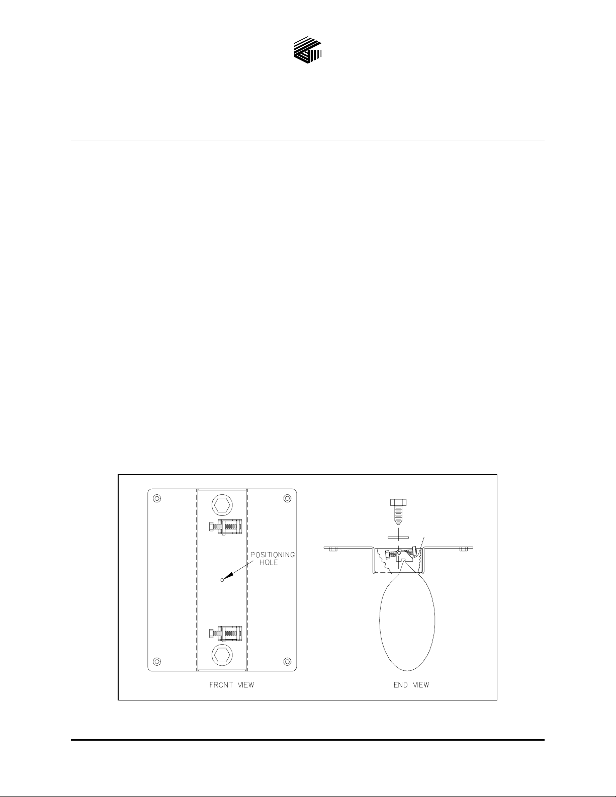
Installing the Band
With t he s crew fu lly retr acted, slip the free end of t he b and through one of the ou ter s lots in t he rear of the
bracket. Be sure that the clamp is positioned with the bolt head opposite the outer slot to allow for
clearance. S ee Figure 1.
Figure 1. Installing the Ba nd
GAI-Tronics Corporation P.O. Box 1060, Reading, PA 19607-1060 USA
610-777-1374 800-492-1212 Fax : 610-796-5954
ISIT WWW.GAI-TRONICS.COM FOR PRODUCT LITERATURE AND MANUALS
V
Page 2
Pub. 42004-099A
Model 231-001 Pole Mounting Kit Page:
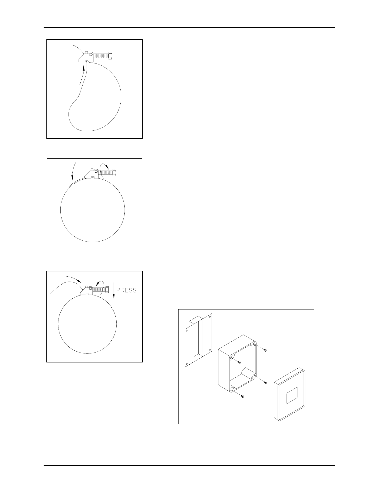
Put the band around the p ole and back thr ough the center slot in
the bracket, then through the clamp. See Figure 2.
Tightening the Band
Pull the band tight, and maintain the tens ion while tightening the
bolt. See Figure 3.
Removing the Band
Loosen the b olt to t he fully retrac ted position. P ress down on the
bolt, and feed t he loos e end of the strap back throu gh the slots.
Figure 2. Installing the Ba nd
See Figu re 4.
Mounting the Enclosure
NOTE: The following steps should b e completed only aft er the
bracket has been mounted to the pole.
2 of 2
Figure 3. Tightening the Band
Figure 4. Removing the Band
1. Loosen t he four capt ive screws , and swing the fr ont door op en
to the left . Dis c onnect any cables or connectors, and pull the
front assembly unit away from the rear enclosure. If the unit
is equipped with hinges, remove them by pulling them out of
the rea r enclosure ho l es.
2. Mount the rear enclosure to the brac ket u sing the Phillip s
Fillister head 1/4-20 by ½- inc h ma chine s c rews. Refer to
Figure 5.
3. Replace the fr ont as sembly, a nd reconnect all the ca bles.
Tighten the fou r out er screws.
Figure 5. Mounti ng the Enclosure
\\s_eng\gtc proddoc s \ s t andard iom s - current release\42004 inst r. m anuals \ 42004-099a. doc
7/97
 Loading...