

Page 1

Pub. 42004-349F
GAI-TRONICS® CORPORATION
A HUBBELL COMPANY
Models 226-003, 246-003, 256-003, and 276-003
S.M.A.R.T. Phones with Keypads
TABLE OF C ONTENTS
Getting Started ........................................................................................................................... 1
Product Overview..............................................................................................................................1
Standard Operation...........................................................................................................................2
Volume Control Button.................................................................................................................................. 2
To Receive a Call...........................................................................................................................................2
To Place a Call...............................................................................................................................................2
Installation................................................................................................................................. 3
Safety Guidelines...............................................................................................................................3
General Installation Guidelines.........................................................................................................3
Tamper-Resistant Hardware........................................................................................................................... 3
Conduit Installation Details............................................................................................................................ 3
Model 226-003....................................................................................................................................5
Model 246-003....................................................................................................................................7
Model 256-003....................................................................................................................................9
Model 276-003..................................................................................................................................11
Stanchion or Flush-mount Applications........................................................................................................ 11
Surface Mount Applications......................................................................................................................... 12
External Power................................................................................................................................ 13
Setup ........................................................................................................................................ 13
Hardware Configuration................................................................................................................. 13
Auto-answer Co nfiguration.......................................................................................................................... 13
Polarity Configuration.................................................................................................................................. 13
Auxiliary Output .............................................................................................................................14
Programming...................................................................................................................................15
Enter the Programming Mode.......................................................................................................................15
Basic Programming...................................................................................................................................... 16
Maintenance.............................................................................................................................17
Service .............................................................................................................................................. 17
Preventive Maintenance for Model 276-003................................................................................... 17
Cleaning...................................................................................................................................................... 17
Prevention.................................................................................................................................................... 17
Specifications................................................................................................................. ..........18
Confidentiality Notice...............................................................................................................21
GAI-Tronics Corporation 400 E. Wyomissing Av e. Mohnton, PA 19540 USA
610-777-1374 800-492-1212 Fax: 610-796-5954
ISIT WWW.GAI-TRONICS.COM FOR PRODUCT LITERATURE AND MANUALS
V
Page 2
PUB. 42004-349F
GAI-TRONICS® CORPORATION
A HUBBELL COMPANY
Models 226-003, 246-003, 256-003, and 276-003
S.M.A.R.T. Phones with Keypads
Getting Started
Product Overview
Thank you for your purchase of a GAI-Tronics S.M.A.R.T. telephone. In addition to providing standard
emergency telephone operation, GAI-Tronics Self-Monitoring and Reporting Telephones (S.M.A.R.T.)
incorporate leading-edge technology to provide optimum performance and flexibility. For example, when
used with the GAI-Tronics Telephone Management Application (TMA) the health of each telephone is
monitored and reported. For complete details, please refer to the on-line help included with TMA.
This manual applies to the following GAI-Tronics S.M.A.R.T. phones that include a 12-button keypad, a
volume co ntro l push b utton, and a noise-canc e ling handset:
Model Description
226-003 Tough S.M.A.R.T. Phone with Keypad – This weather-resist ant, vanda l - resistant, s and-
cas ted aluminum unit is provi ded with a s pring-loa ded d o or and a handset wi th an armored
cord. It is designed for use in remote areas under extreme conditions.
246-003 Rugged Indoor S.M.A.R.T. Phone with Keypad – This phone is housed in a high impact
glass-reinforced polyester enclosure designed to withstand operator abuse.
256-003 Rugged Weatherproof S.M.A.R.T. Phone with Keypad – The enclosure for this phone is
made of weatherproof, high impact glass-reinforced polyester, and can be equipped with a
spring-loaded door.
276-003 Flush-panel S.M.A.R.T Phone with Keypad – This is a flush-mount phone with a heavy-
gauge brushed stainless steel front panel that is designed to be wall-mounted indoors. It
includes an armored cord.
The GAI-Tronics S.M.A.R.T. Phone product line provides the flexibility to address a diverse range of
applications. A wi de variet y of functions can b e achieved by alteri ng the conf igur atio n data st ored in the
phone’s non-volatile memory. These configuration options include:
• Ca ll progress detection, control, and call logging
• Auto-calling, auto-answering, and auto-dialing facilities
• Function inhibiting (e.g. tone pad and manual keypad dialing)
• Ma ximum call duration
These functi o ns are initially progra mme d during ma nufactu ring an d testing. After installa tion, they c an
be progra mme d remotel y via DT MF data call.
GAI-Tronics Corporation 400 E. Wyomissing Av e. Mohnton, PA 19540 USA
610-777-1374 800-492-1212 Fax: 610-796-5954
ISIT WWW.GAI-TRONICS.COM FOR PRODUCT LITERATURE AND MANUALS
V
Page 3

Pub. 42004-349F
S.M.A.R.T.
PHONES WITH KEYPADS PAGE 2 of 21
All S.M.A.R.T. telephones are line-powered and can be connected to any of the following:
• Central Office (CO) line to the Public Switched Telephone Network (PSTN)
• 24 V dc or 48 V dc analog station port of Private Branch Exchange (PBX), Private Automatic Branch
Exchange (PABX) or KSU.
Connection may not be made to pay phone extensions or shared service (party) lines.
TM A users can s c he dule auto-dia l maintena nce calls to aler t maintena nce person nel of any unusual sensor
or fault conditions that exist. S.M.A.R.T. Phones can also be programmed to generate an auto-dial
mai ntenance call whe n certain sensor ev e nts are di sco vere d. Access t o the S.M.A.R . T. Phone’s
mai ntenance mo de is restricted throug h the use of t he mai ntena nce access PIN. The mainte nance acc ess
PIN should be distributed only to trained maintenance personnel.
Standard Operation
Volum e Contro l Button
The volume control button on the front of each phone is used to control the handset volume. Each press
of the button increases the volume in four steps and then returns it to the original setting in a circular
fashion.
To Receive a Call
When the telephone rings:
1. Lift the handset.
2. Converse with the caller.
3. When finished, hang up the handset.
To Place a Call
To place a call using manual dialing:
1. Lift the handset.
2. Dial the desired telephone number.
3. Convers e wit h the perso n answering the call.
4. When finished, hang up the handset.
f:\standard ioms - current release\42004 instr. m anuals\42004-349f.doc
04/09
Page 4

Pub. 42004-349F
S.M.A.R.T.
PHONES WITH KEYPADS PAGE 3 of 21
Installation
ATTENTION
Installation should be performed by qualified personnel and only in
accordance with the National Elec trical Code or applicable loc al cod es.
Safety Guidelines
When installing any GAI-Tronics telephone equipment, please adhere to the following guidelines to
ensure the safety of all personnel:
• Do not install telephone wiring during a lightning storm.
• E lectrostatic Discharge (ESD) Protection: Your telephone may have an earth ground terminal
provision. If so, ensure that it is connected to ground in accordance with all local safety regulations
and the National Electrical Code (NEC). Grounding has to be ensured for safe and stable
communications. Do not u se lon g and co iled ground wires. Trim ground wires to the requ ired
length. Use a star configuration whenever possible. Please note proper grounding does not eliminate
the need for lightning protection for the telephone or the telephone system.
• Install a UL Listed lightning arrestor on any phone installed where the phone or phone cable is at
ris k of bei ng exposed to lig htning strikes . The l ight ning arr es tor must b e installed as cl ose as poss i ble
to maximize the protection. It must not be installed within the enclosure supplied with the phone.
Please consult our Service Center at 800-492-1212 for further information.
• Do not install telephone jacks in wet locations unless the jack is specifically designed for wet
locations.
• Do not touch uninsulated telephone wires or terminals unless the telephone line has been
disconnected at the network interface.
General Installation Guidelines
GAI-Tronics S.M.A.R.T. phones are designed to operate on telephone lines as detailed in the Product
Overview section of this manual. The telephones are designed to operate with one telephone per line. If
telephones are operated in parallel or “party line configuration” you may experience sporadic phone
operation, difficulties with programming, or premature disconnection of calls. Additionally, if special
features, e.g. voice mail, call waiting, etc, are not disabled, the phone may not function.
Tamper-Resistant Hardware
Models 226-003 and 276-003 are vandal resistant, with the front panel for each telephone attached to its
enclosure with tamper-resistant screws. A GAI-Tronics Model 233-001 Tamper-Resistant Screwdriver
(sold separately) is recommended for installing the tamper-resistant screws. Models 246-003 and 256003 Telephones’ front panels are attached with standard Phillips head screws.
Conduit In stallation D etails
GAI-Tronics recommends installing telephone lines in conduit to protect against accidental damage and
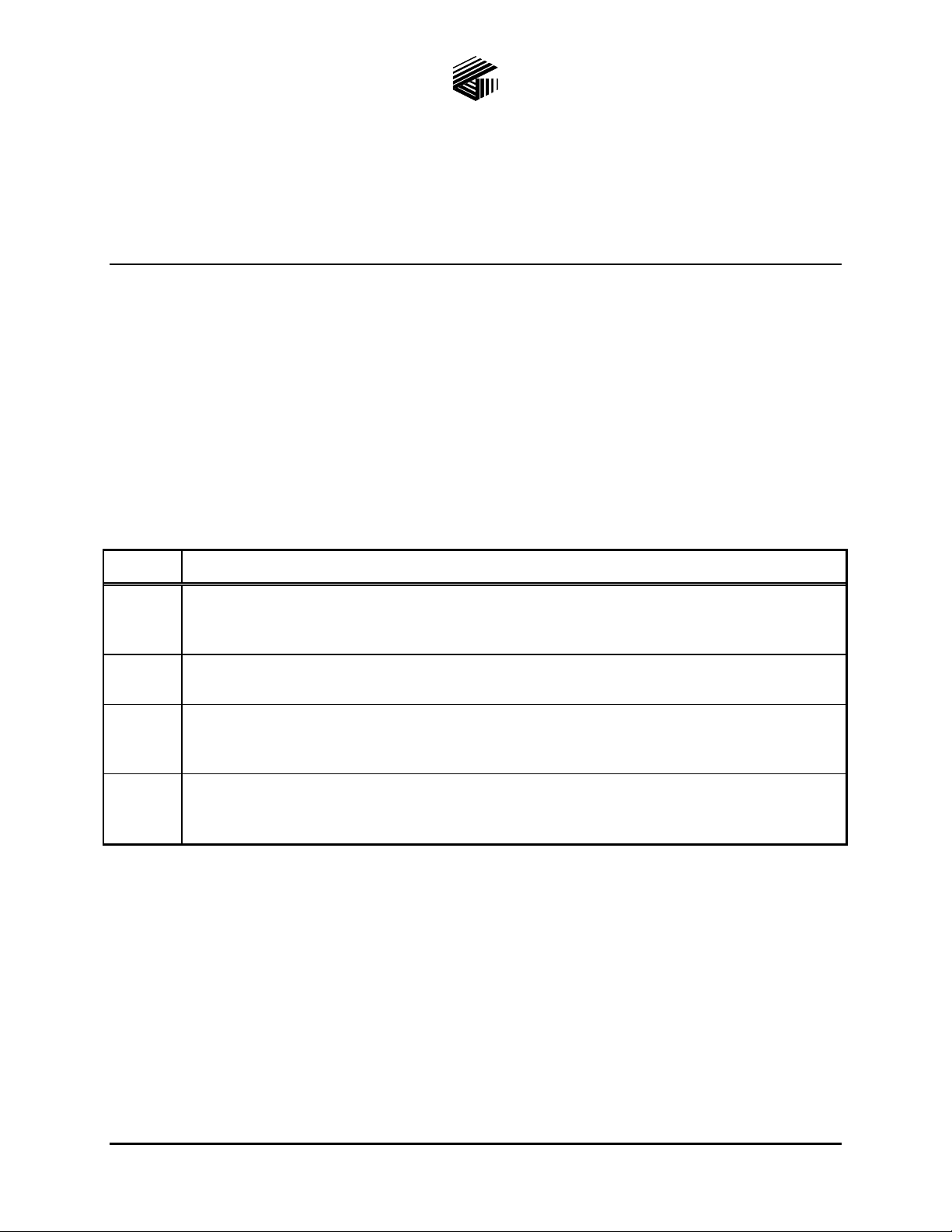
vandalism. To prevent moisture from entering the enclosure, we strongly recommend the following:
• Conduit should enter the enclosure from the bottom.
• Sealed fittings should be installed at all cable entry points.
• Silicone sealant or equivalent should be applied around and inside all conduit entries.
f:\standard ioms - current release\42004 instr. m anuals\42004-349f.doc
04/09
Page 5
Pub. 42004-349F
S.M.A.R.T.
PHONES WITH KEYPADS PAGE 4 of 21
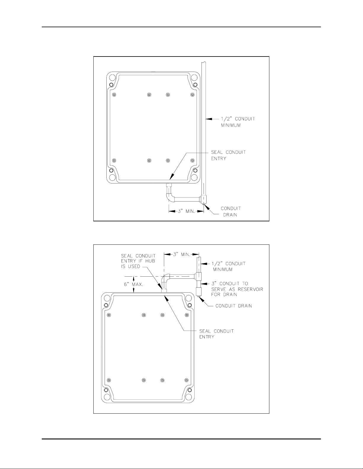
Please refer to Figu re 1 and Figu re 2 as examples of rec ommen d e d con duit installation d et ails.
OTE: See page 5 for the Model 226-003 Telephone.
N
Figure 1. Bottom entry conduit installation details (RECOMMENDED for non-metallic enclosures)
Figure 2. Top entry conduit installation details (NOT RECOMMENDED)
f:\standard ioms - current release\42004 instr. m anuals\42004-349f.doc
04/09
Page 6
Pub. 42004-349F
S.M.A.R.T.
PHONES WITH KEYPADS PAGE 5 of 21
Model 226-003
The mounting and wiring instructions for the Model 226-003 S.M.A.R.T. are as follows:
1. Remov e th e ei ght tamper-resistant
screws from the front panel.
Remove the front panel and set
aside.
N
OTE: Th ere is a 7-f oot h alf-
modular telephone cord attached to
th e PC B A on the rear.
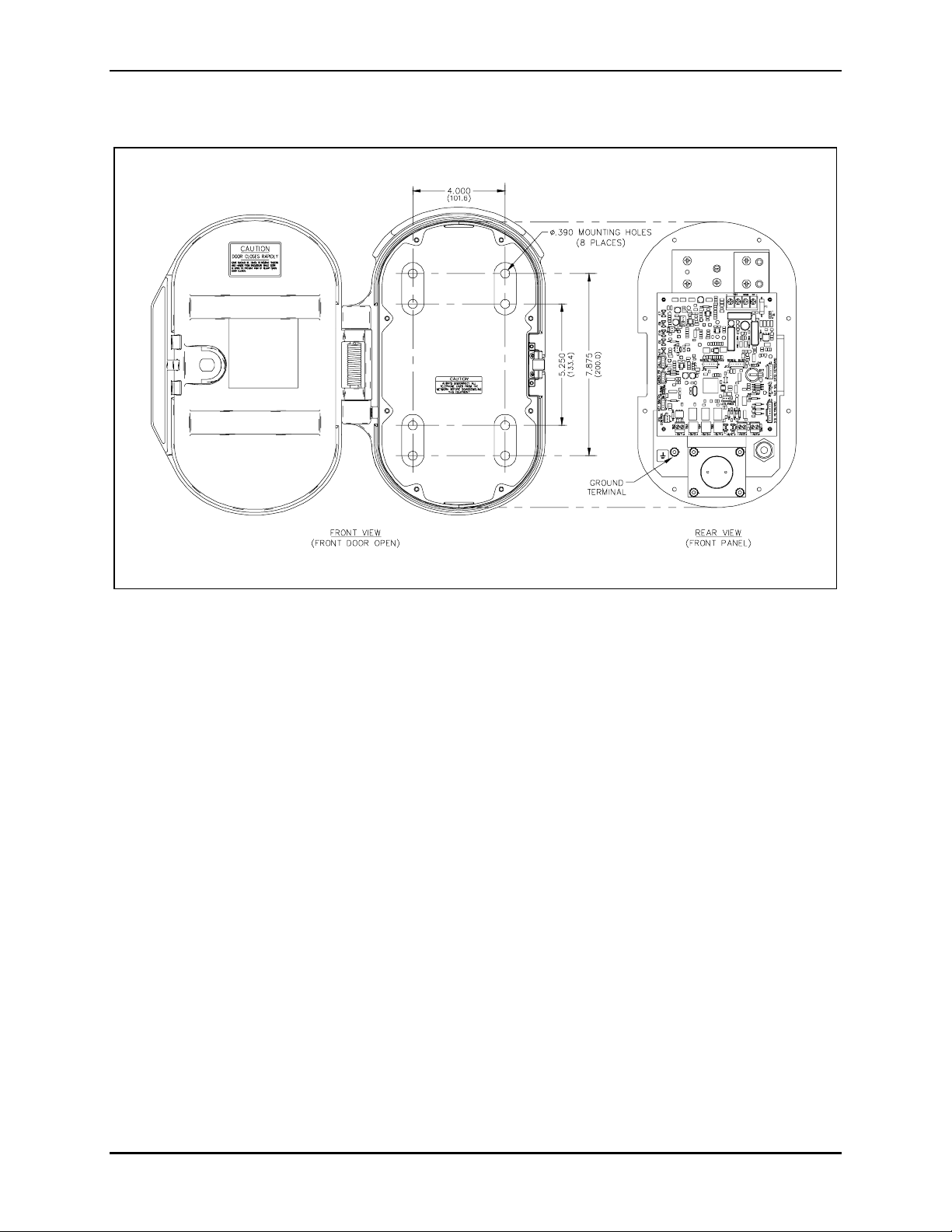
2. There are ei ght m o unti n g holes in
the back of the enclosure in two 4hole patterns. Determine which hole
pattern will be used for mounting.
See Figure 5.
• For best results, use the
7.875 × 4.0-inch hole pattern for
mounting to a wall (outside
pattern).
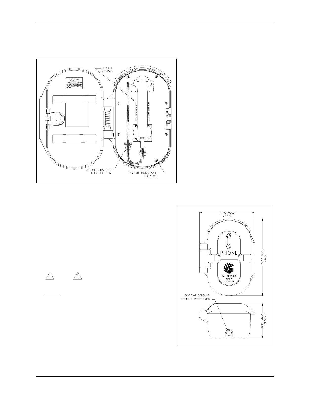
Figure 3. Model 226-003 S.M.A.R.T. Phone with spring
loaded door in the open position
3. Insert four hole plugs (provided) in the unused holes.
4. Posit ion the enclosure o n the mountin g surface and
secure it with four fasteners.
• T he holes in the telephone enclosure accept 3/8-inch
screws or bolts.
• T he Model 232-001 Pole Mounting Kit includes four
3/8-16 × 1-inch shoulder bolts with Teflon seal
washers.
NOTE
Use only the round head, hexagon
hea d , or pan hea d scre ws that a re provide d.
Do not
use screws designed to be countersunk for
mounting the enclosure.
5. Install a conduit fitting in one of the 1/2-inch NPT
conduit entrances provided at both the top and bottom of
the unit, and insert the conduit into the fitting. (The
bottom location is preferred. See Figure 4.) Plug the
unused access hole using the 3/8-inch Allen drive plug
provided.
• Use the 5.25 × 4.0-inch hole
pattern when using the Model
232-001 Pole Mounting Kit
(inside pattern).
f:\standard ioms - current release\42004 instr. m anuals\42004-349f.doc
04/09
Figure 4. Model 226-003 Outline
Page 7
Pub. 42004-349F
S.M.A.R.T.
PHONES WITH KEYPADS PAGE 6 of 21
6. Fish the free end of the half-modular telephone cord through the conduit.
Figure 5. Model 226-003 Mounting Details
7. Replace the front panel assembly, and secure using the eight front panel tamper-resistant screws.
8. Connect the free end of the telephone cord to the incoming subscriber line using a USOC RJ11C jack
(USA) or CA11A jack (Canada). Verify operation by calling to and from another phone.
f:\standard ioms - current release\42004 instr. m anuals\42004-349f.doc
04/09
Page 8

Pub. 42004-349F
S.M.A.R.T.
PHONES WITH KEYPADS PAGE 7 of 21
Model 246-003
1. Remove the four screws from the front panel. Remove the front panel and set aside.
OTE: There is a 7-foot half-modular telephone cord attached to the PCBA on the rear.
N
2. There are fou r mountin g holes i n rear en cl osure. Mount the e n cl osure t o the wall using either f o ur ¼ -
20 machine screws with washers and nuts or four #14 wood screws of the appropriate length,
depending on the mounting surface.
3. Drill a 0.688-diameter hole at either drill spot on the bottom of the rear enclosure, and attach the
gland bushing.
4. Fish the free end of the telephone cord through the gland bushing.
5. Replace the front panel assembly and tighten the four front panel screws.
6. Connect the free end of the half-modular telephone cord to the incoming subscriber line using a
USOC RJ11C jack (USA) or CA11 A jack (Canada). Veri fy op eration by calling to and from a nother
phone.
Figure 6. Model 246-003 S.M.A.R.T. Phone
f:\standard ioms - current release\42004 instr. m anuals\42004-349f.doc
04/09
Page 9

Pub. 42004-349F
S.M.A.R.T.
PHONES WITH KEYPADS PAGE 8 of 21
Figure 7. Model 246-003 Mounting Details
f:\standard ioms - current release\42004 instr. m anuals\42004-349f.doc
04/09
Page 10

Pub. 42004-349F
S.M.A.R.T.
PHONES WITH KEYPADS PAGE 9 of 21
Model 256-003
1. Open the front door and remove the four outer screws from the mid-section. Carefully pull the
enclosure apart until encountering a slight resistance on the left side.
2. Pull on the left side of the enclosure until the hinge plugs pull loose to separate the front and rear
halves. Set the front half of the enclosure aside.
3. There are fou r mountin g holes i n th e rear encl o sure. Mount the enclosure on the wal l using four ¼- 20
machine screws with nuts and washers or #14 wood screws of appropriate length for the mounting
surface.
4. Drill a 0.688-diameter hole at either drill spot on the bottom of the rear enclosure, and attach the
gland bushing.
5. Reinsert the hinge pins to attach the front half of the enclosure. Fish the free end of the telephone
cord through the gland bushing.
6. Close the mid-section and tighten th e four scre ws.
7. Connect the free end of the modular telephone cord to the incoming subscriber line using a USOC
RJ11C jack (USA) or a CA11A jack (Canada). Check the telephone by calling to and from another
phone.
Figure 8. Model 256-003 S.M.A.R.T. Phone Outline
(Front door open)
f:\standard ioms - current release\42004 instr. m anuals\42004-349f.doc
04/09
Page 11

Pub. 42004-349F
S.M.A.R.T.
PHONES WITH KEYPADS PAGE 10 of 21
Figure 9. Model 256-003 Mounting Details
f:\standard ioms - current release\42004 instr. m anuals\42004-349f.doc
04/09
Page 12

Pub. 42004-349F
S.M.A.R.T.
PHONES WITH KEYPADS PAGE 11 of 21
Model 276-003
Figure 10. Model 276-003 Outline Drawing
Stanchion or Flush-mo unt Applicat ions
1. When mounting in a GAI-Tronics Model 234 Series Stanchion or for flush-mount installations, the
supplied back box must be used to mount the Model 276-003 Telephone. Mount the back box to the
structure using the appropriate hardware. Refer to Figure 11 cutout dimensions.
2. If mounted outdoors, install the telephone line suppressor (customer-supplied) on the telephone line.
3. Remove the tapered plug from the top or bottom cable entry hole in the back box, and install the
telephone line and cable fitting.
4. Use silicone sealant or equivalent around and inside all conduit entries.
5. Attach the telephone’s front panel to the mounting flanges of the back box using the six supplied
#10-32 tamper-resistant screws and washers.
6. Connect the USOC RJ11C (USA) or CA11A (Canada) modular connector of the supplied telephone
cord to the incoming subscriber line, or (if applicable) the telephone line suppressor using the
appropriate mating connector. Check the telephone by calling to and from another phone.
f:\standard ioms - current release\42004 instr. m anuals\42004-349f.doc
04/09
Page 13

Pub. 42004-349F
S.M.A.R.T.
Surface Moun t Applications
PHONES WITH KEYPADS PAGE 12 of 21
NOTE: The back box is not required for use with the Model 236 Series Surface Mount Enclosure and
shou ld be remove d.
1. Drill or punch conduit entries.
WARNING
To prevent accidentally damaging equipment, drill all holes before
mounting the telephone.
2. Use silicone sealant or equivalent around the telephone gasket and the mounting surface for an
effe ctive perimeter seal. T his is pa rticu l arly i mportant if t he mountin g s urface is un even.
3. Install the telephone line suppressor (customer-supplied) on the telephone line, if applicable.
4. Attach the telephone’s front panel to the mounting flanges of the Model 236 Surface Mount
Enclosure using the six #10-32 tamper-resistant screws and washers provided.
5. Connect the USOC RJ11C (USA) or CA11A (Canada) modular connector of the supplied telephone
cord to the incoming subscriber line, or (if applicable) the telephone line suppressor using the
appropriate mating connector. Check the telephone by calling to and from another phone.
Figure 11. Model 276-003 Mounting Details
f:\standard ioms - current release\42004 instr. m anuals\42004-349f.doc
04/09
Page 14

Pub. 42004-349F
S.M.A.R.T.
PHONES WITH KEYPADS PAGE 13 of 21
External Power
The Model 40404-045 Plug-in Power Supply is available (sold separately) to provide an increase in the
emergency phone’s speaker output and a reduction in line current consumption. The 40404-045 requires
120 V ac input and provides a 5 V dc output to the unit’s speaker amplifier circuits. The 40404-045 is
provided with a connectorized, 4-foot power cable that plugs into P17 on the telephone PCBA.
N
OTE: The 40404-045 is required only when setting the normal speaker volume to maximum does not
produce the desired results or if available telephone line current falls below acceptable results.
Setup
Hardware Configuration
The hardware configuration options are explained in detail in the following sections and the necessary
jumper settings are identified to enable or disable each option. We recommend reading the following
sections , recordi ng the desired pa rameters, and t hen making the n e cessary chang e s. We a l so rec o mmend
that you make a record of your settings. The following options are controlled by specific hardware
configurations. See Figure 12 on page 14 for the jumper locations.
Auto-ans wer Configuration
Factory Setting: Auto-answer featur e enabled
The Auto-answer feature enables or disables the automatic answering of an incoming call, which allows
TMA to monitor the health of this phone via polling. When the Auto-answer feature is enabled, the
phone automatically answers the call and attempts to communicate with TMA. If the caller is not TMA,
then the phone rings its sounder to alert a user to lift the handset off-hook.
Enable: Insert the J14 jumper on pins 2 and 3.
Disable: Insert the J14 jumper on pins 1 and 2 (Do not use this setting except under the direction of
GAI-Tronics personnel.)
OTE: The Auto-answer feature must be enabled during remote programming, and to allow the
N
GAI-Tronics Telephone Management Application PC to contact the phone.
Polarity Conf iguration
Factory Setting: Non-polarity sensitiv e
This telephone can be configured to be polarity or non-polarity sensitive. With the non-polarized setting,
the telephone operates with the telephone line’s positive terminal connected to either the tip or the ring.
With the polarized setting, the telephone only operates with the telephone line’s positive terminal
connect ed to th e tip.
Non-polarity Sensitive: Insert the J6 jumper on pins 2 and 3.
Polarity Sensitive: Insert the J6 jumper on pins 1 and 2.
f:\standard ioms - current release\42004 instr. m anuals\42004-349f.doc
04/09
Page 15

Pub. 42004-349F
S.M.A.R.T.
PHONES WITH KEYPADS PAGE 14 of 21
Auxiliary Output
Each telephone includes one isolated solid state switch capable of switching a maximum of 48 V dc, 125
mA or 28 Vrms ac, 80 mArms. TB2 (OUT1) on the phone PCBA provides the connections for the
auxiliar y output. R efer to Figure 12 f or the location of the TB2.
The auxiliary output allows for control of external electric devices such as a ringing indicator lamp. This
isolated contact output activates while the telephone sounds its ringer at the start of an incoming call and
will extinguish when the handset is lifted from its cradle (call answered).
This aux iliary ou tput can b e ma nual ly activated (a f ter a 2 -seco nd delay) wh e n the calle d party pr es ses th e
DTMF + or # ke y. The relay then remains a c tive for th e duratio n of the call.
Figure 12. S.M.A.R.T. Phone PCBA
f:\standard ioms - current release\42004 instr. m anuals\42004-349f.doc
04/09
Page 16

Pub. 42004-349F
S.M.A.R.T.
PHONES WITH KEYPADS PAGE 15 of 21
Programming
All S.M.A.R.T. Phone models are programmable. The phone settings are initially programmed during
manufacturing and testing. These default settings from the factory can be found in Table R-2. After the
S.M.A.R.T. Phone is installed, you have the option of changing the default settings. This manual
provides instructions for programming basic features needed to initially set up the phone from another
touch-tone phone.
More adva nced programmi ng r e quir es a PC a nd the T MA software. For programming using the TMA
terminal, refer to the manual provided with the software, or contact the GAI-Tronics Field Service
Department.
NOTE
Use a handset phone exclusively when programming the S.M.A.R.T. phone remotely. If a speakerphone
is used for programming background noise could lead to the incorrect settings. (Cellular telephone is not
recommended.)
Enter the Progr amming Mode
Read the entire programming section and carefully plan your programming before beginning the process.
Write down the key sequence from the Command column of Table R-1, Basic Programming Commands,
for the features that you need. Having your programming information written down allows you to enter
the key sequence at a steady pace.
Complete the following steps to enter the programming sequence from a remote DTMF telephone:
1. Call the S.M.A.R.T. telephone to be programmed. (Do not use a cellular phone.)
2. Listen for a confirmation tone during ringing, which signals that the telephone has answered.
3. Press
*** to enter the programming mode.
4. Wait two seconds.
5. Enter **0000
OTE: After sending the maintenance PIN # to the phone, entering *20 will allow for co nfirmati on
N
(0000 is the factory default maintenance PIN #.)
of maintenance access to the phone. If access is granted, the phone responds with 6 DTMF digits.
If access is denied, the phone responds with two DTMF digits. If access is denied, repeat step 5 to
again request access.
6. Complete the desired programming. Refer to the Basic Programming Commands section for options.
7. Listen for a confirmation tone at the end of each programming sequence, which indicates the
programming change was accepted.
NOTE
Delays during programming greater than 5 seconds cause a programming time-out. If this occurs,
you will hear a beep before the programming sequence is completed and you must reenter the
sequence.
8. When finished programming, press *99 to exit the programming mode.
f:\standard ioms - current release\42004 instr. m anuals\42004-349f.doc
04/09
Page 17

Pub. 42004-349F
S.M.A.R.T.
Basic Prog ramming
PHONES WITH KEYPADS PAGE 16 of 21
The following programming command can be entered from any touch-tone telephone. Acceptance of a
data transfer command is indicated via a return code transmitted as an audible DTMF tone.
Call Tim e-out
The call time-out feature, which is used to limit the duration of calls, can be set between one minute and
4.5 hours. The time limit is set by entering a number from 120 to 32400.
This number represents the number of half-second increments of duration. Entering 0 results in a call
time -out of 4.5 hours.
Enter *37<120~32400>#
to assign a time limit, or change an existing time limit.
*37 Dat a tr ansf er comma nd
<120~32400>
Call duration (60–16,200 seconds, 0 = 4.5 hours) – See example
below.
# End of string indicator
Multiply the desired time limit, in minutes, by 120 to determine the call duration.
Exa mple: For a c all dur ation of 5 minu tes :
5 minutes × 120 = 600
Therefore, you would enter the c h arac ter string *37600#, and the phone returns a system-generated
DTMF check-digit.
Table R-1 - Basic Programming Commands
Command: Return: Description:
*37<120~32400># c
Write Call Time-out (120-32400 × ½ sec, 0 disables)
‘c’ in the above return fields is the system-generated DTMF check-digit.
Table R-2 - Default Configuration
Parameter Default Setting
Auto-answer Enabled (J14)
Rings Bef ore Auto-answer 0 (not configurable)
Rings After Auto-answer 10 ( not co nfigu ra ble)
Dial Tone Detection Enabled (N/A unless keypad is disabled)
Dial Tone Waiting Period 10 seconds
Mute Before Dial Enabled
Audio Receive Level Midrange
Call Time Out Perio d 7 min
DTMF Dial Rate 100:100 ms
f:\standard ioms - current release\42004 instr. m anuals\42004-349f.doc
04/09
Page 18

Pub. 42004-349F
S.M.A.R.T.
PHONES WITH KEYPADS PAGE 17 of 21
Maintenance
Service
If you r S. M.A.R.T. Phone requires service, c onta c t your GAI-Tr onics Regio nal S ervic e Cent er for a
return authorization number (RA#). Equipment should be shipped prepaid to GAI-Tronics with a return
authorization number and a purchase order number. If the equipment is under warranty, repairs will be
made without charge. Please include a written explanation of all defects to assist our technicians in their
tr oubleshootin g e f for ts.
Call 800-492-1212 inside the USA or 610-777-1374 outside the USA for help identifying the Regional
Service Center closest to y o u.
Preventive Maintenance for Model 276- 003
Stainless steel does not require maintenance to prevent corrosion from occurring. Different installation
locations may require more regular maintenance than others, depending on the environment and exposure
to ai rbor ne contami nants . The follow ing ma inte nanc e steps should be performed on a regular basi s or
when corrosion is first noticed on your Model 276-003.
Cleaning
• For gen era l clean ing, wipe the s ur fac e with a cleans er or a cleanser an d water mixture. Any c leanser
that is safe for glass is usually safe for stainless steel. Wipe dry.
• I f c orrosion or rusting is notic e d, re mo ve wit h a non-ab rasive commerc ial cleanser a nd wat er. Ru b
stained areas in the same direction as the existing grain. Stubborn stains may be removed with a
mag nesium oxide, ammoni a, and wa ter p ast e. Wipe clea n w i th wa ter rinse and dr y.
Prevention
Automotive wax provides the best results in preventing corrosion on stainless steel. Simply apply wax,
let dry to a haze, and buff to a shine with a clean dry cloth. This application should protect the telephone
surfac e for many mont hs as it will a llow natural r ef orma tion of t he chromium oxid e layer .
Do NOT use steel wool, s a ndpaper, miner a l aci ds , bleaches, o r chlorine clea ns ers on the stainless
surface.
f:\standard ioms - current release\42004 instr. m anuals\42004-349f.doc
04/09
Page 19

Pub. 42004-349F
S.M.A.R.T.
PHONES WITH KEYPADS PAGE 18 of 21
Specification s
TMA Compatibility profile type........................................................................GTC S.M.A.R.T. Handset
Electrical
Minimum loop current (48 V dc only) ............................................................................................ 20 mA
Operation.................................................................................................................................. Loop start
Volume control ...................................................................................... 4 step (-6 dB, 0 dB, 6 dB, 12 dB)
Auxiliary output (isolated solid state switch)................................................................48 V dc @ 125 mA
28 V
Mechanical
Operating temperature range.............................................................................................-40º C to +60º C
Relative humidity................................................................................................ to 95%, no condensation
Model 226-003
Construction
Enclosure.....................................................Thick-walled cast aluminum with protective gray coating
Panel.................................................................................................... 0.125-inch brushed aluminum
Handset/cord.........................................................G-style with 19-inch armored cord and internal lanyard
Braille dial pad............................................................................................................Chrome-plat ed zin c
Dimensions .......................................................................................... 13.50 H × 9.7 0 W × 6.15 D inches
Mounting ...................................................................................................Eight 0.39-inch diameter holes
Weight .........................................................................................................................................14.5 lbs.
@ 80 mA
RMS
RMS
Model 246-003
Construction..................................................................................High impact, glass-reinforced polyester
Handset/cord..........................................................................6-foot Hytrel cord with noise-canceling mic
Braille dial pad............................................................................................................Chrome-plat ed zin c
Dimensions ............................................................................................ 9.50 H × 8.00 W × 6.90 D inches
Mounting ....................................................................................................Four 0.28-inch diameter holes
Weight ...........................................................................................................................................4.8 lbs.
Model 256-003
Construction..................................................................................High impact, glass-reinforced polyester
Handset/cord..........................................................................6-foot Hytrel cord with noise-canceling mic
Braille dial pad............................................................................................................Chrome-plat ed zin c
Dimensions .......................................................................................... 13.20 H × 9.4 0 W × 7.40 D inches
Mounting ....................................................................................................Four 0.28-inch diameter holes
Weight .........................................................................................................................................10.0 lbs.
f:\standard ioms - current release\42004 instr. m anuals\42004-349f.doc
04/09
Page 20

Pub. 42004-349F
S.M.A.R.T.
PHONES WITH KEYPADS PAGE 19 of 21
Model 276-003
Construction
Front Panel.......................................................14-gauge (0.075 inch) type 304 brushed stainless steel
Back Box.........................................16-gauge (0.060) cold-rolled steel with black polyurethane finish
Handset/cord.........................................................G-style with 29-inch armored cord and internal lanyard
Braille dial pad............................................................................................................Chrome-plat ed zin c
Dimensions
Front Panel.................................................................................................. 12.00 H × 10.00 W inches
Back Box....................................................................................... 10.06 H × 8.4 3 W × 2.44 D inches
Back Box (depth from mounting surface)...........................................................................2.38 inches
Panel Cutout .................................................................................................10.06 H × 8.43 W inches
Weight ...........................................................................................................................................7.0 lbs.
Approvals
Safety of Information Technology Equipment....................................................................UL/CSA 60950
Enclosures for Electrical Equipment.................................................................................UL 50, Type 3R
Model 246-003 only: UL 50
47 CFR Part 68
Certification Number....................................................................................... US: ADGTE04B0414HAC
Ringer Equivalence Number .............................................................................................................. .4B
Network connection (USOC)............................................................................................................. RJ11
IC Information (Canada)
IC Certification Number........................................................................................882B-GTC S.M.A.R.T.
Ringer Equivalence Number .............................................................................................................. .4B
Connection Method.......................................................................................................................CA11A
f:\standard ioms - current release\42004 instr. m anuals\42004-349f.doc
04/09
Page 21

Pub. 42004-349F
S.M.A.R.T.
PHONES WITH KEYPADS PAGE 20 of 21
User Instructions (USA)
This equ ipment com plies with Part 68 of th e F C C r u les and the r equiremen ts adopted b y th e ACTA. On this
equip ment is a label that cont ains, among other informati on, a product identifier in th e format
US:AAAEQ##TXXXX. If requested , th i s num ber must be provided t o th e telephone company.
A plug an d jack used to connect this equipmen t to the premises wiring and telep hone networ k must comp ly with the
applicable FCC Part 68 rules and requirements adopted by the ACTA. A compliant telephone cord and modular
plug is provided with this product. It is designed to be connected to a compatible modular jack that is also
compliant. See installation instructions for details.
The REN is u sed to determ ine the number of devices that may be con nected to a teleph on e line. Excessi ve RENs on
the telephon e line may resul t in the devices not rin ging in response to an incoming cal l. In most but n ot al l areas, th e
sum of th e RE Ns should not ex ceed five (5. 0 ) . To be cer tain of th e n um ber of devices that ma y be con nected to a
line, as determined by the total RENs, contact the local telephone company. For products approved after July 23,
2001, the REN for this product is part of the product identifier that has the format US:AAAEQ##TXXXX. The
digits represented by ## are the REN without a decimal point (e.g., 03 is an REN of 0.3). For earlier products, the
REN is separately shown on the label.
If this equipment [GAI-Tronics telephone] causes harm to the telephone network, the telephone company will notify
you in advance that temporary discontinuance of service may be required. But if advance notice isn’t practical, the
telephone company will notify the customer as soon as possible. Also, you will be advised of your right to file a
complaint with the FCC if you believe it is necessary.
The telephon e com p any may mak e changes in it s fa cilities, equipmen t , operati ons, or proced u res that could affect
the operation of the equipment. If this happens the telephone company will provide advance notice in order for you
to make necessary modifications to maintain uninterrupted service.
If tr oubl e is experienced with this eq ui pm en t [GAI-Tronics telephon e] , for repair or warranty informati on , please
contact GAI-Tronics Corporation at 800-492-1212 or www.gai-tronics.com. If the equipment is causing harm to the
telephone net wor k , the tel ephone company may reques t that you disconnect the equ ip ment until the problem is
resolved.
Connection to party line service is subject to state tariffs. Contact the state public utility commission, public service
commission or corporation commission for information.
This equ ipment uses a telephone hands et and it is hearing aid compatible.
User Instructions (Canada) CP-01, Issue 8, Part I: Section 14.1
NOTICE: The Industry Canada la bel identifies certified equ ipment. Th is certification means that th e eq uipment
meets certain t elecommun ications network protecti ve, opera tional an d safety req u irements as prescr ibed in the
appr opriate T erm inal Equipment Tech n ical Requirements document (s). Th e Department d oes not guarantee the
equip ment will operate to the user's satisfaction. Befor e installing thi s eq u ip ment, users shoul d en sure that it is
permissible to be connected to the facilities of the local telecommunications company. The equipment must also be
inst alled using an accepta bl e method of connect ion. The custom er shoul d be a ware that compliance with the abo ve
conditions may not prevent degradation of service in some situations. Repairs to certified equipment should be
coordinated by a representative designated by the supplier. Any repairs or alterations made by the user to this
equipment, or equipment malfunctions, may give the telecommunications company cause to request the user to
discon nect the equipmen t. Users shoul d ensure for their own prot ection that the electrica l ground conn ections of the
power u tility, telephon e lines and in ternal metallic wat er pipe system, if present, are con nected together. Th is
precaution may be particularly important in rural areas.
CAUTION
Users should not attempt to make such connections themselves, but should contact the appropriate electric
inspection authority, or electrician, as appropriate.
CP-01, Issue 8, Part I: Section 14.2
NOTICE: The Ringer Equivalenc e Number (RE N ) assigned t o ea ch terminal device pr ovides an indicati on of the
maximum number of terminals allowed to be connected to a telephone interface. The termination on an interface
may consist of any combination of devices subject only to the requirement that the sum of the Ringer Equivalence
Number s of a ll the device s d oes not exceed 5.
f:\standard ioms - current release\42004 instr. m anuals\42004-349f.doc
04/09
Page 22

Pub. 42004-349F
S.M.A.R.T.
PHONES WITH KEYPADS PAGE 21 of 21
Replacem ent Parts
Part No.
233-001 Model 233-001 Tamper-Resistant Screwdriver
12562-104 PCBA Replacement Kit (S.M.A.R.T. Handset)
51035-005 PCBA, Keypad
13707-008 Ringer
Description
226-
003
246-
003
256-
003
28299-007 Tamperproof Screws (Torx – T25)
28229-002 Tamperproof Screws (Torx – T25)
28118-001 Phillips Head Screws
10113-020 Handset Assembly with Armored Cord, 15-inch
10113-021 Handset Assembly with Armored Cord, 29-inch
10113-022 Hytrel Cord Handset Assembly, 6-foot
12512-001 Hookswitch/Cradle Kit
12512-002 Hookswitch/Cradle Kit (metallic)
12576-118 Front Panel Replacement Kit
40404-045 Optional Plug-in Power Supply
276-
003
Confidentiality Notice
This manua l is pr ov ided s olel y as an installation, operati on, a nd maintenance guid e and contai ns sensiti ve
business and technical information that is confidential and proprietary to GAI-Tronics. GAI-Tronics
retains all intellectual property and other rights in or to the information contained herein, and such
information may only be used in connection with the operation of your GAI-Tronics product or system.
This manua l may not be dis closed in any form, i n whol e or in part, directly or indirect ly, t o any t hird party.
f:\standard ioms - current release\42004 instr. m anuals\42004-349f.doc
04/09
Page 23

Warranty
Equipment. GAI-Tronics warrants for a period of one (1) year from the date of shipment, that any
GAI-Tronics equipment supplied hereunder shall be free of defects in material and workmanship, shall
comply with the then-current product specifications and product literature, and if applicable, shall be fit
for the purpose specified in the agreed-upon quotation or proposal document. If (a) Seller’s goods prove
to be defective in workmanship and/or material under normal and proper usage, or unfit for the purpose
specified and agreed upon, and (b) Buyer’s claim is made within the warranty period set forth above,
Buyer may return such goods to GAI-Tronics’ nearest depot repair facility, freight prepaid, at which time
they will be repaired or replaced, at Seller’s option, without charge to Buyer. Repair or replacement shall
be Buyer’s sole and exclusive remedy. The warranty period on any repaired or replacement equipment
shall be the greater of the ninety (90) day repair warranty or one (1) year from the date the original
equipment was shipped. In no event shall GAI-Tronics warranty obligations with respect to equipment
exceed 100% of the total cost of the equipment supplied hereunder. Buyer may also be entitled to the
manufacturer’s warranty on any third-party goods supplied by GAI-Tronics hereunder. The applicability
of any such third-party warranty will be determined by GAI-Tronics.
Services. Any services GAI-Tronics provides hereunder, whether directly or through subcontractors,
shall be performed in accordance with the standard of care with which such services are normally
provided in the industry. If the services fail to meet the applicable industry standard, GAI-Tronics will
re-perform such services at no cost to buyer to correct said deficiency to Company's satisfaction provided
any and all issues are identified prior to the demobilization of the Contractor’s personnel from the work
site. Re-performance of services shall be Buyer’s sole and exclusive remedy, and in no event shall GAITronics warranty obligations with respect to services exceed 100% of the total cost of the services
provided hereunder.
Warranty Periods. Every claim by Buyer alleging a defect in the goods and/or services provided
hereunder shall be deemed waived unless such claim is made in writing within the applicable warranty
periods as set forth above. Provided, however, that if the defect complained of is latent and not
discoverable within the above warranty periods, every claim arising on account of such latent defect shall
be deemed waived unless it is made in writing within a reasonable time after such latent defect is or
should have been discovered by Buyer.
Limitations / Exclusions. The warranties herein shall not apply to, and GAI-Tronics shall not be
responsible for, any damage to the goods or failure of the services supplied hereunder, to the extent
caused by Buyer’s neglect, failure to follow operational and maintenance procedures provided with the
equipment, or the use of technicians not specifically authorized by GAI-Tronics to maintain or service the
equipment. THE WARRANTIES AND REMEDIES CONTAINED HEREIN ARE IN LIEU OF AND
EXCLUDE ALL OTHER WARRANTIES AND REMEDIES, WHETHER EXPRESS OR IMPLIED BY
OPERATION OF LAW OR OTHERWISE, INCLUDING ANY WARRANTIES OF
MERCHANTABILITY OR FITNESS FOR A PARTICULAR PURPOSE.
Return Policy
If the equipment requires service, contact your Regional Service Center for a return authorization number
(RA#). Equipment should be shipped prepaid to GAI-Tronics with a return authorization number and a
purchase order number. If the equipment is under warranty, repairs or a replacement will be made in
accordance with the warranty policy set forth above. Please include a written explanation of all defects to
assist our technicians in their troubleshooting efforts.
Call 800-492-1212 (inside the USA) or 610-777-1374 (outside the USA) for help identifying the
Regional Service Center closest to you.
(Rev. 10/06)
 Loading...