

Page 1
Pub. 42004-245B
GAI-TRONICS® CORPORATION
A HUBBELL COMPANY
Model 1931888-3011
Page/Party
Confidentiality Notice
This manual is pr ovided s olely as a n op erat ional, installation, and maintenance guide and contains sens itive
bus ines s and t echnic al infor ma tion which is conf idential and propriet ary to GAI-Tronics. GAI - Tronic s
retains a ll intellectual pr operty and other rights in or to t he inf ormation c ontained herein, and s uch
informa tion may only be used in connection wit h the operation of you r GAI- Tronic s pr oduct or system.
This ma nual may not be disclosed in any form, in whole or in p art, dir ec tly or indirectly, to any t hird pa rty.
General Information
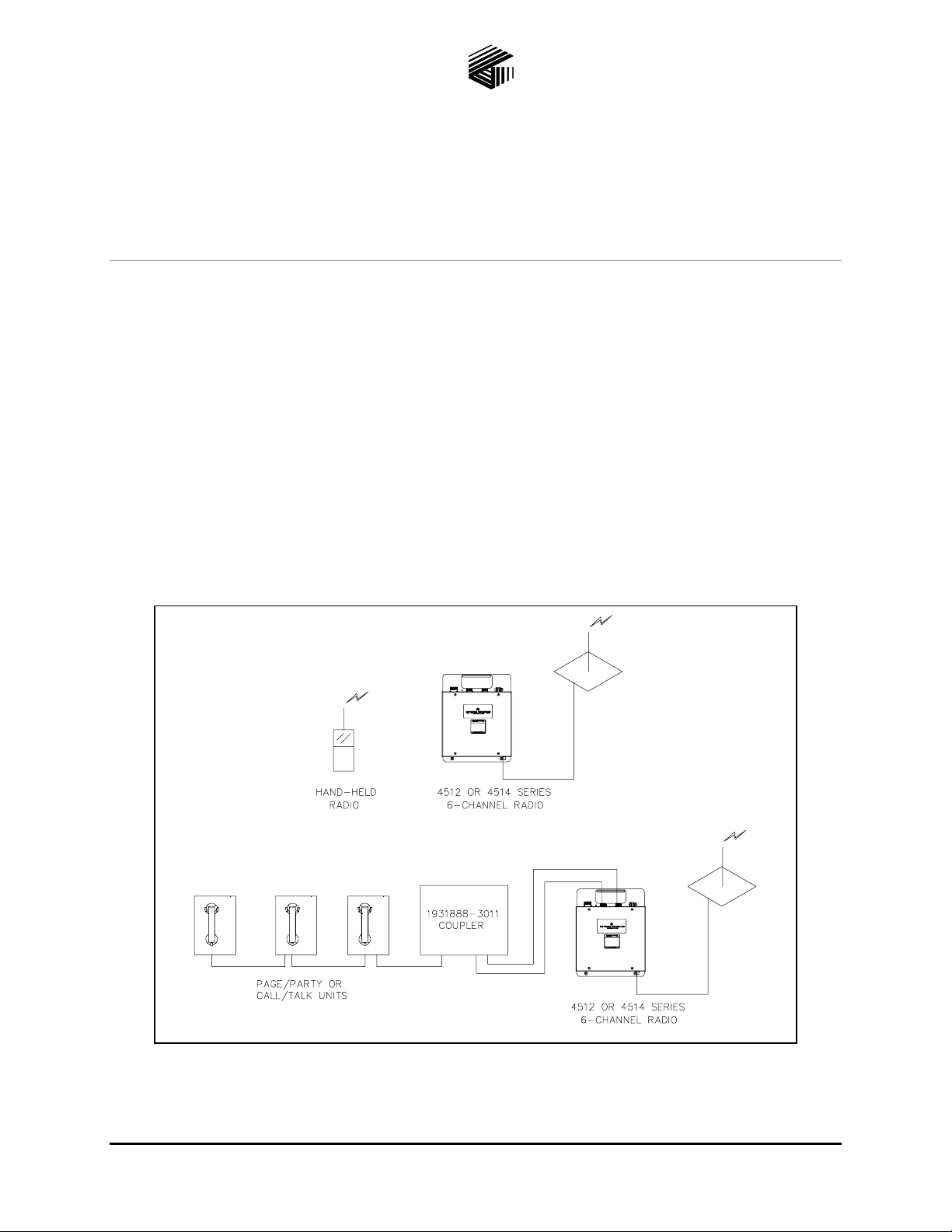
The Model 1931888-3011 Coupler, when connected to a GAI - Tr onic s 4512 or 4514 Series 6-Channel
Ra dio, allows a GAI-Tr onic s Page/Party
hand-held or mobile u nits. Radio u sers tra veling ou tside the facility at a remote location or ins ide a pla nt,
can communicate with Page/Party
®
or C all/Talk users. Plea se see Figure 1 for installation layouts.
®
to Radio C oupler
®
or C all/Talk s ystem to communicate with other 6-C hannel Radio
Figure 1. Installat i on L ayout D i agram
GAI-Tronics Corporation P.O. Box 1060, Reading, PA 19607-1060 USA
610-777-1374 800-492-1212 Fax : 610-796-5954
ISIT WWW.GAI-TRONICS.COM FOR PRODUCT LITERATURE AND MANUALS
V
Page 2
Model 1931888-3011 Page/ P ar ty
®
to Radio Coupler Page: 2 of 10
Installation and Wiring
Pub. 42004-245B
Punch or drill a hole in the left s i de or left bottom of the coupler a nd insta ll a conduit fitting. This entry is
®
for system c abl e fro m the Page/Par ty
or Call/Talk system to the coupler. Sealed threaded hubs, such as
Myers Scru-Tite (1.25-inch) are recommended.
Since the Model 1931888-3011 coupler must be connected t o a GAI-Tronic s 6-C hannel Ra dio, mount t he
coupler and radio in a place where the antenna f or the radio may be appropria tely positioned. R efer to t he
GAI-Tronics 4512 and 4514 Series 6-Channel Radio manual, Pub. 42004-387, for antenna placement
information.
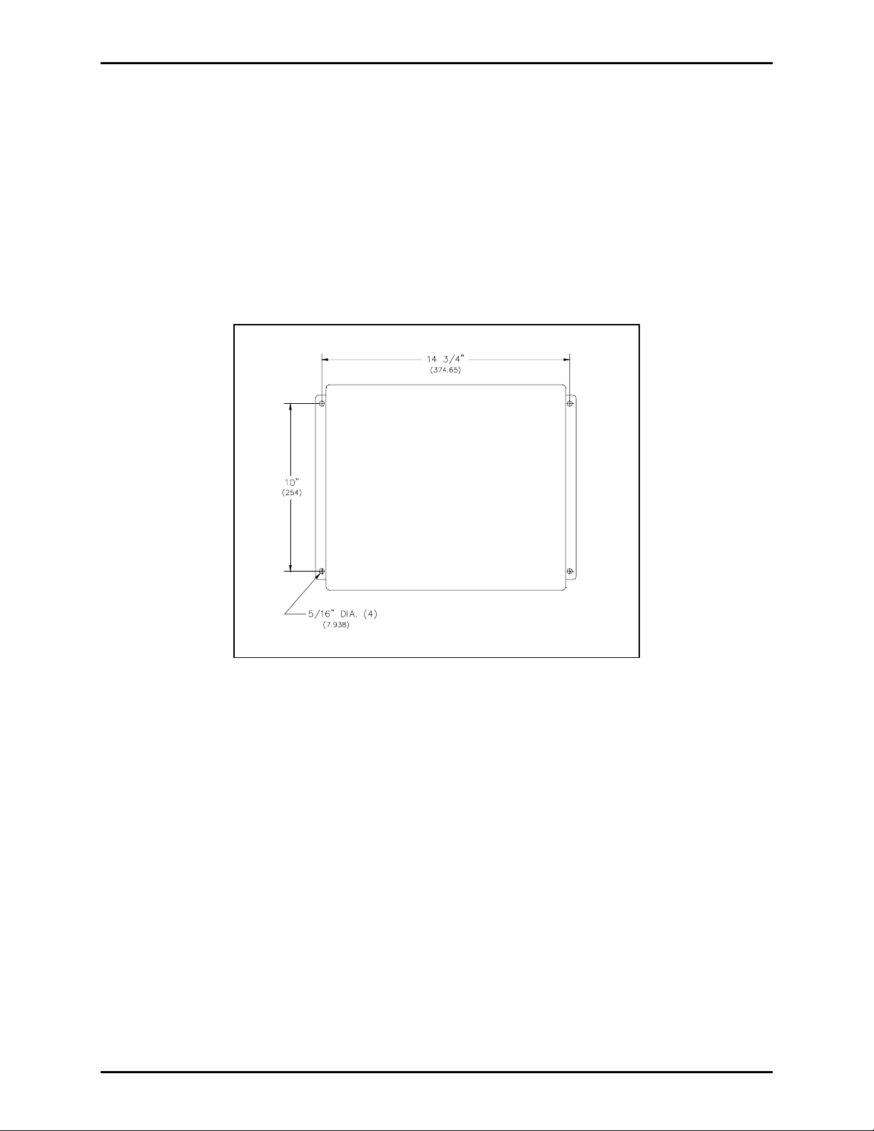
The coupler should be wall-mounted using the four 5/16-inch (7.938 mm) mounting holes. See Figure 2
for dimensions .
Figure 2. Mounting D et ails
®
Use GAI-Tronics 60038-101 system cable to connect t he cl osest Page/Party
or C all/Talk stat ion to the
coupler:
®
1. Connect the 120 V ac power conductors, blac k, white, and green with yellow, fr om t he Page/Party
or
Call/Talk station to TB-1, TB-2, and TB-5 respectively in the coupler.
2. Use the r ed wit h blue and blue with red twist ed p air to connect the page line L1 and L2 in the station to
TB- 3 and T B-4 respectively.
3. Use the r ed and ta n with red t wis ted pair to c onnect pa rty line 5 ( or designated part y line) L1 a nd L 2
from the s tation to T B - 7 and TB-8 respectively.
OTE: Party line 5 is used here for explanation purposes.
N
4. TB- 6 and TB-9 throu gh TB-1 4 are factory connec tions.
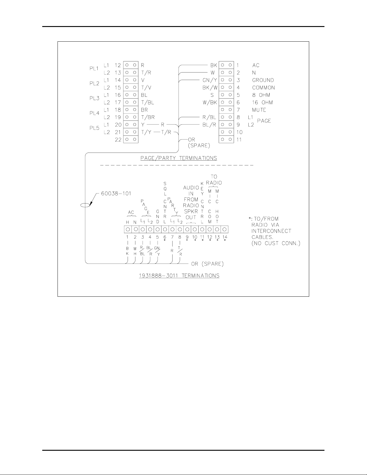
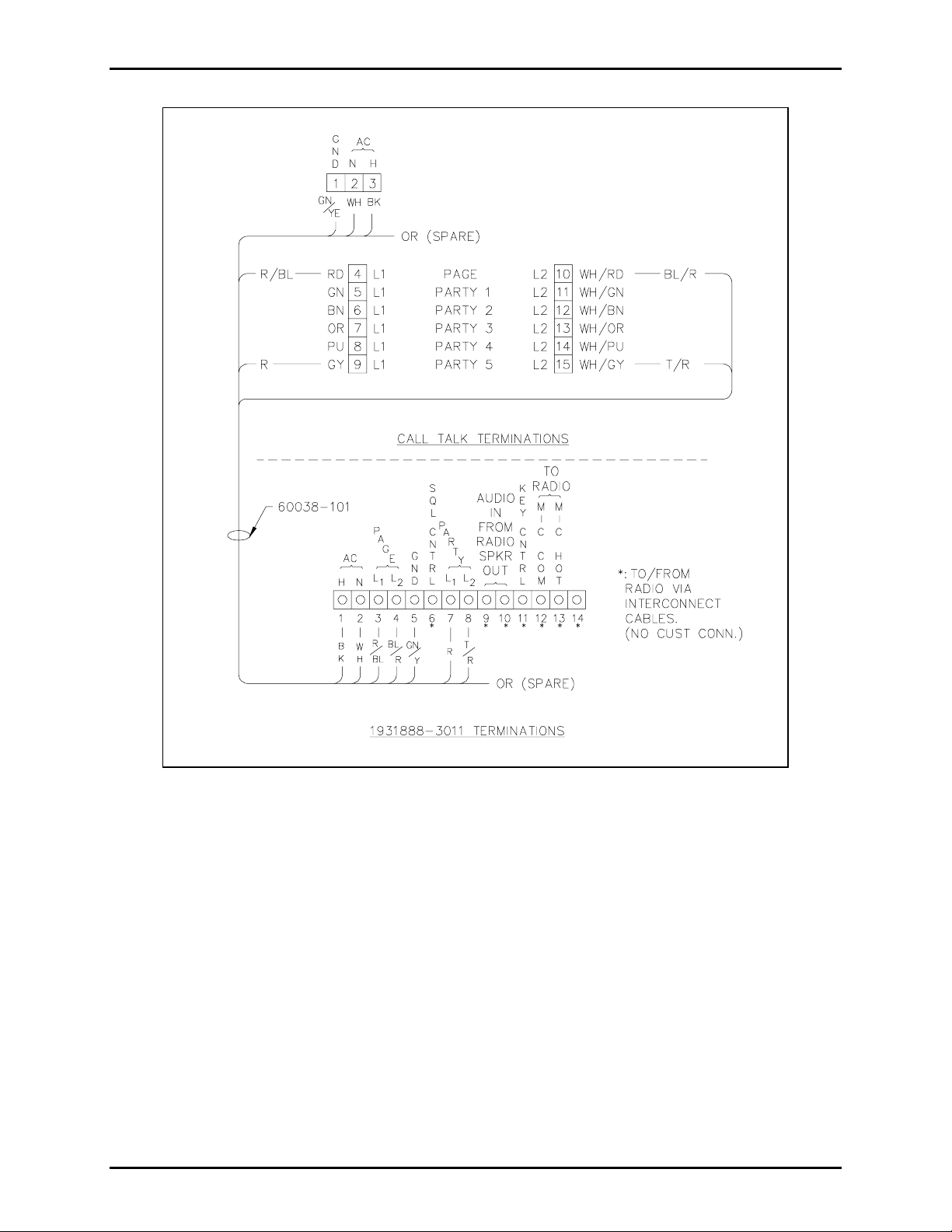
Figure 3 a nd Figure 4 show t he terminal blocks in the Page/Pa rty
®
and Call/Talk s tat ions, respect ively, as
well as t he 14-lug t erminal block in the coupler. C ables wit h three-prong and f our-prong military s tyle MS
connectors a re included wit h the coupl er. These cables connect from t he b ottom of the coupler to the top of
the radio.
\\s_eng\gtc proddoc s \ s t andard iom s - current release\42004 inst r. m anuals \ 42004-245b. doc
03/08
Page 3
Model 1931888-3011 Page/ P ar ty
®
to Radio Coupler Page: 3 of 10
Pub. 42004-245B
Figure 3. W i ring/Termination Deta ils for Page/ Party
®
NOTE: Jumper P6 on the GAI-Tronic s 6-C hannel Ra dio must be ins talled in positions 2-3 for pr oper
®
operation when used with the Model 1931888-3011 Page/Party
\\s_eng\gtc proddoc s \ s t andard iom s - current release\42004 inst r. m anuals \ 42004-245b. doc
03/08
to Radio Cou p l er.
Page 4
Model 1931888-3011 Page/ P ar ty
®
to Radio Coupler Page: 4 of 10
Pub. 42004-245B
Figure 4. W iring/Terminations for Ca ll/Talk
\\s_eng\gtc proddoc s \ s t andard iom s - current release\42004 inst r. m anuals \ 42004-245b. doc
03/08
Page 5

Model 1931888-3011 Page/ P ar ty
Operation
®
to Radio Coupler Page: 5 of 10
Pub. 42004-245B
The Model 1931888-3011 Coupler connects one radio frequ enc y ( c hannel) to one party line in the
®
Page/Party
or C all/Talk system, usually par ty line 5. When a remote radio is not in u se, the cou pler
monitors p arty line 5.
In order for a Page/P arty
®
or C all/Talk u ser to c ontact a radio user, the caller must go off - hook on party
line 5. The resulting communicat i on is simplex. This means that the ra dio u ser cont rols t he flow of the
conversation wit h the pus h- to-talk, release-t o- listen mechanism of the ra dio.
Call Originated by a Page/Party® or Call/Talk User to a Radio User
Audio Path from Page/Party® to Radio
The ca ller from a Pa ge/ Party® or C all/Talk s tat ion goes off-hook on the designated party line. This ca uses
the station’s output transformer to load the line (loop current on the line begins) at the Model 19318883011 coupler’s TB-7 and 8 and is detected by the Model WBA2757 Sensing PCBA inside the coupler.
The following relay fu nc tions occur:
1. The sens ing PCBA det ects the of f - hook c ondition on the party line and a c tivates the
illuminates L ED 3.
2. The
XFR (transfer) relay is ac tivated by the sens ing PCBA. I t transfers the audio p ath from the
‘Radio-Page’ line to the ‘Radio-Party’ line.
3. The
VOX board detects audio from the system par ty line. When su fficient s ystem party line a udio is
present, it activates VX1 relay and illuminates LED 1 .
XFR relay a nd
VX1 (VOX) r elay toggle oper ation is activated by the Voice Operated Switch (VOX) PCBA. While the
4.
relay is activated:
• It p rovides the audio connect ion pat h f rom the part y line t o the ra dio’s microphone-in cir c uit (TB-
12 and 13) via the coupler’s
• It disables
SQ1 (squelc h) relay during party line talk mode for uninterrup ted communicati on.
RADIO VOL c ontrol (VC1).
• It p rovides a c ontact closure a t TB- 11 to ground t o key t he radio transmitt er circ uitry.
\\s_eng\gtc proddoc s \ s t andard iom s - current release\42004 inst r. m anuals \ 42004-245b. doc
03/08
Page 6

Model 1931888-3011 Page/ P ar ty
Audio Path from Radio to Page/Party®
®
to Radio Coupler Page: 6 of 10
Pub. 42004-245B
1. After the Page/Party® caller has fi nished speaking, the r adio us er can simply key the microp hone t o
answer.
2. When the coup ler’s radio receives the signal, t he audio signal ap pears at the coupler’s TB-9 and 10 via
the 3-wire interc onnect cab l e assembly. Squelch c ontrol is also provided from t he radio t o the
coupler’s TB-6 via the same interconnect cab l e.
3. With t he s qu elc h c ontrol present, the following r elay functions occur:
•
SQ1 (squelch) relay is activated by SQUELCH cont rol fr om t he radio a nd illuminates LED 2 .
This p rovides the audio connect ion pat h f rom ‘Radio-Part y’ line via the
and disables
•
XFR (transfer) relay stays active to maintain the audio path from the radio to the Page/Party
VX1 relay for uninterru p ted party communications f rom the radio.
UA VOL cont rol (VC2),
®
system’s party line.
• VX1 (VOX) relay is disabled by SQ1 relay for unint erru pted part y c ommunications f rom the radio.
The signal pa th continu es in this manner until bot h parties have completed their c onversa tion.
Call Originated by Radio User to Page/Party® or Call/Talk System Page Line
Audio Path from Radio to Page/Party®
1. The r adio user makes a call b y simply keying the microp hone and ta lking (pus h- to-talk/release-t o-
listen) after first ensuring that the channel is clear.
2. When the coupler’s radio receives the signal, the audio signal will ap p ear at the cou pler’s TB-9 and 10.
Also, the SQUE L CH cont rol signal is provided from t he radio at T B - 6 via 3- wire inter c onnect cable
assembly.
3. With S QUELC H control signa l present , the following relay fu nc tions occur:
®
• XFR (tr ansfer) relay is inac tive (no pa rty line loop c urrent is present [ Page/Party
hook]) and LED 3 is off. This result s in maintaining the audio path from t he radio to the
®
Page/Party
system’s page line.
• SQ1 ( squelch) relay is activated by SQUELCH control signal from r adio and illuminates LED 2.
This provides the audio connection pa th fr om ‘Radio-Page’ line (p age line TB-3 and 4 ) via the UA
VOL control (VC2), and disables VX 1 rela y f or unint erru pted communica tions from ra dio to the
®
Page/Party
system’s pa ging speakers.
• VX1 (VOX) relay is disabled by SQ1 relay.
stations on-
Audio Path from Page/Party® to Radio
The called party goes to a P age/P arty® station, selects the dedicated party line, a nd goes of f-hook. This
®
causes the Page/Party
station’s outp ut transformer to load t he line (loop c urrent on the line begins) at the
Model 1931888-3011 Coupler’s TB-7 and 8 and is detected by the sensing PCBA within the coupler. For
®
a cont inued expla nation of the subsequent events, refer to the Call Originated by Page/Part y
or Call/Talk
User to Ra dio section.
\\s_eng\gtc proddoc s \ s t andard iom s - current release\42004 inst r. m anuals \ 42004-245b. doc
03/08
Page 7

Pub. 42004-245B
Model 1931888-3011 Page/ P ar ty
®
to Radio Coupler Page: 7 of 10
Time-Out Timers
The coupler is equipped with two timer boards labeled TMR #1 and TMR #2. The fu nc tion of the boards
is provided to limit the t rans mis sion times of both the sys tem and radio.
TMR #1
The T MR #1 boa rd is controlled by the VOX board du ring part y line communication from the Page/Party®
syst em to the ra dio. When VOX control s ignal is p resent at T MR #1’s p in 1 (sys tem talk mode), the
outp ut a t pin 2 is pulled low t o activate the VX 1 rela y. When pa rty line a udio is no longer present on the
line, the VOX output is removed and the VX1 relay drops- out to permit radio respons e.
However, if the station r emains off-hook on the party line and noise levels occur, the VOX will det ect the
levels on the line, a nd key t he radio. Under this c ondition, the timer board will ti me-out and dis able the
VX1 relay to remove radio keying control after app roximately one minute.
TMR #2
The TMR #2 board is controlled by SQUELCH control fr om the radio t o Page/ Party® system’s party line
communications. When the
output at pin 2 is pulled low to activate the SQ1 relay.
SQUELCH control s i gnal is present at T MR #2’s pi n 3 (radio ta lk mode), the
When ra dio
resp onse. However , if the radio remains in receive mode with
SQUELCH control and audio is no longer present, the SQ 1 relay drops - out to permit system
SQUELCH control, pa rty line a udio cannot
be tr ansmitted back to the radio system. Under this condition, the timer boar d will time-out a nd disab le t he
SQ1 relay t o remove radio
SQUELCH control after approx ima tely one minute.
Maintenance
Control Functions
The Model 1931888-3011 Coupler contains four adjustment controls which have been pre-adjusted at the
fac tory. Minor adjus tments may b e neces sary for optimum sys tem performance. Refer t o Figure 5.
Control Description:
®
• UA VOL: Adjust s the au dio level being coupled to t he P age/Party
ra dio’ s speaker out. C loc kwise rotation of the contr ol inc reas es the audio drive level.
• RADIO
Page/Party
• VOX
VOL: Adjusts the audio level being coup l ed t o the ra dio’ s microphone- in c ircuitry f rom the
®
or C all/Talk s ys tem. Clockwise rotation of the contr ol inc reas es the audio drive level.
SENS: Adjusts the thr es hold level (activa tion point] f or the Voice Oper ated X s wit c h c ircuitry
to ac tivat e. Clockwise rotation of the contr ol inc reases the sensitivity level.
or C all/Talk system from the
• TRANSFER
SENS: Adjust s the threshold level for the TR AN SFE R detection c ircuitry to act i vate.
Clockwis e rota tion of the control increases the thres hold level for XFR relay activation when a n
®
associated Page/Party
\\s_eng\gtc proddoc s \ s t andard iom s - current release\42004 inst r. m anuals \ 42004-245b. doc
03/08
station is off-hook.
Page 8

Model 1931888-3011 Page/ P ar ty
®
to Radio Coupler Page: 8 of 10
Pub. 42004-245B
Figure 5. Part Location Diagram
Typical audio signal levels within coupler from Page/Party® station to coupler:
With approximately 1. 5 Vrms on Page/Party® system party line (TB-7 and 8); with an associated
Page/Party
®
station off - hook:
Audio signal at TB- 12 (com) and 13; Mic I n = ap proximately 0.45 Vrms, nominal
(Radio Vol. Min/Max range = 0 V/1.24 Vrms)
Typical audio signal levels from coupler to Page/Party® station:
• With approximately 10 Vrms of rec eived speaker audio at T B - 9 and 10; wit h X FR relay’s LED 3
®
NOT illuminated a nd all associa ted Page/ Party
stations on-hook:
Audio signal at TB- 3 and 4 (page line) = 0.5 Vrms** nominal.
(UA Vol. Min/Max ra nge = 0 V/ 3.0 Vrms**)
• With approximately 10 Vrms of rec eived speaker audio at T B 9 and 10; with XFR relay’s LED 3
®
illuminat ed and an a ssociated Page/Party
station off - hook:
Audio signal at TB- 7 and 8 (party line) = 0.5 Vrms** nominal.
(UA Vol. Min/Max ra nge = 0 V/ 3.0 Vrms**)
**Voltages indica ted ar e t ypical with indicated signal levels, actua l voltages measur ed may vary with
different audio dr ive levels.
\\s_eng\gtc proddoc s \ s t andard iom s - current release\42004 inst r. m anuals \ 42004-245b. doc
03/08
Page 9

Model 1931888-3011 Page/ P ar ty
Troubleshooting
®
to Radio Coupler Page: 9 of 10
Pub. 42004-245B
Problem
The r adio oper ator can not
make a p age to t he
®
Page/Party
or Call/Talk
system’s pa ging speakers,
but c an communica te on
designated party line.
Page/Party® system user
has low modu lation audio
to r adio oper ator.
While the Page/Party®
station is off-hook, the
associated coupler’s XFR
relay activates, but VX1
relay does NOT activat e
when speaking into
handset.
Visual LED
Indication
XFR relay LE D is
illuminated.
1. Check for possible off - hook Page/ Party
stations and/or low res ista nc e on the
Solution
designated party line a nd c orrect as necessary.
2. Check a dju stment of TRANSFER
Fa c tory setting = approx . ¼ turn CW fr om
mini mum. (F ull y CCW)
N/A 1. Check adju stment of RADIO
adjust as necessary.
Fa c tory s etting = app roximately mid ra nge.
2. Check for pr op er jumper loc ation of J2 inside
the associat ed radio u n i t.
(For coup ler operation, J2 must be in Pos. 2 and 3
versus Pos.1 and 2 [f actory set ting])
XFR relay LE D is
illuminat ed and VX1
relay L ED is NO T
illuminated.
1. Check a dju stment of VOX
SENS pot.
(Factory setting = approx. ¼ turn CW from
mini mum. [F ull y CCW])
2. Check for defective VOX PCB assembly.
Replace WBA4417, if necessary.
®
SENS pot.
VOL. pot. Re-
No communications in
either direction.
No communication fr om
ra dio opera tor to
®
Page/Party
station is
possible, but
communicat i ons from
®
Page/Party
station t o
ra dio opera tor are OK.
Ca rrier detect does not
act i vate on 6- Channel
Ra dio. Does not funct ion.
No rela y L EDs a re lit
in any mode.
1. Check for proper ac supply voltage to coupler
at TB-1 and 2.
2. Check FU1. Replace, if necessary, with fuse
of the same value a nd rating.
3. Check CO1B power supply. Replace, if
necessary.
4. Check ext ernal wiring connect ions.
If SQ 1 relay L ED is
NOT illuminated:
1. Check CC1 module. Replace WBA4259, if
necessary.
2. Chec k speaker ca ble assembly (3-wire
connector) connect ions.
If SQ1 relay LED IS
illuminated:
1. Replace SQ1 relay.
2. Check ext ernal page connect ions to
®
Page/Party
system.
N/A Jumper P6 on 6-Cha nnel R adio must be installed
in positions 2- 3 for prop er operation.
\\s_eng\gtc proddoc s \ s t andard iom s - current release\42004 inst r. m anuals \ 42004-245b. doc
03/08
Page 10

Pub. 42004-245B
Model 1931888-3011 Page/ P ar ty
®
to Radio Coupler Page: 10 of 10
Specifications
Construction/finish:........................... 16-gauge steel, oil resistant gasket, ANSI #61 gray polyester coating,
NEMA-12 rated
Mounting...................................Four 5/16-inch (7.9mm) mounting holes, center to center measurements of
14.75 × 10 inches L × H (374.65 × 254 mm)
Dimensions..................................................... 14 × 12 × 6 inches L × W × D (354.0 × 304. 8 × 152.4 mm)
Shipping weight............................................................................................................... 28 lb. (12.72 kg)
Power requirements:
Voltage................................................................................ 108–132 V ac (50/60 Hz), 120 V ac, nominal
Power Consumed............................................................................................................... 24 VA, 9 watts
Replacement Parts
Refer to Figure 5 for locations.
Item # Part Number Description
1 43276A-7011 Cable Assembly, Microphone
2 43276A-7012 Cable Assembly, Speaker
3 C01B PCBA, Power Supply
4 WBA4417 PCBA, VOX Board Assembly
5 WBA4259 Module, Squelch Control (CC1)
6 45004-005 Relay
7 51812-001 Fuse 2 amp, 125 V
\\s_eng\gtc proddoc s \ s t andard iom s - current release\42004 inst r. m anuals \ 42004-245b. doc
03/08
Page 11

Warranty
Equipment. GAI-Tronics warrants for a period of one (1) year from the date of shipment, that any
GAI-Tronics equipment supplied hereunder shall be free of defects in material and workmanship, shall
comply with the then-current product specifications and product literature, and if applicable, shall be fit
for the purpose specified in the agreed-upon quotation or proposal document. If (a) Seller’s goods prove
to be defective in workmanship and/or material under normal and proper usage, or unfit for the purpose
specified and agreed upon, and (b) Buyer’s claim is made within the warranty period set forth above,
Buyer may return such goods to GAI-Tronics’ nearest depot repair facility, freight prepaid, at which time
they will be repaired or replaced, at Seller’s option, without charge to Buyer. Repair or replacement shall
be Buyer’s sole and exclusive remedy. The warranty period on any repaired or replacement equipment
shall be the greater of the ninety (90) day repair warranty or one (1) year from the date the original
equipment was shipped. In no event shall GAI-Tronics warranty obligations with respect to equipment
exceed 100% of the total cost of the equipment supplied hereunder. Buyer may also be entitled to the
manufacturer’s warranty on any third-party goods supplied by GAI-Tronics hereunder. The applicability
of any such third-party warranty will be determined by GAI-Tronics.
Services. Any services GAI-Tronics provides hereunder, whether directly or through subcontractors,
shall be performed in accordance with the standard of care with which such services are normally
provided in the industry. If the services fail to meet the applicable industry standard, GAI-Tronics will
re-perform such services at no cost to buyer to correct said deficiency to Company's satisfaction provided
any and all issues are identified prior to the demobilization of the Contractor’s personnel from the work
site. Re-performance of services shall be Buyer’s sole and exclusive remedy, and in no event shall GAITronics warranty obligations with respect to services exceed 100% of the total cost of the services
provided hereunder.
Warranty Periods. Every claim by Buyer alleging a defect in the goods and/or services provided
hereunder shall be deemed waived unless such claim is made in writing within the applicable warranty
periods as set forth above. Provided, however, that if the defect complained of is latent and not
discoverable within the above warranty periods, every claim arising on account of such latent defect shall
be deemed waived unless it is made in writing within a reasonable time after such latent defect is or
should have been discovered by Buyer.
Limitations / Exclusions. The warranties herein shall not apply to, and GAI-Tronics shall not be
responsible for, any damage to the goods or failure of the services supplied hereunder, to the extent
caused by Buyer’s neglect, failure to follow operational and maintenance procedures provided with the
equipment, or the use of technicians not specifically authorized by GAI-Tronics to maintain or service the
equipment. THE WARRANTIES AND REMEDIES CONTAINED HEREIN ARE IN LIEU OF AND
EXCLUDE ALL OTHER WARRANTIES AND REMEDIES, WHETHER EXPRESS OR IMPLIED BY
OPERATION OF LAW OR OTHERWISE, INCLUDING ANY WARRANTIES OF
MERCHANTABILITY OR FITNESS FOR A PARTICULAR PURPOSE.
Return Policy
If the equipment requires service, contact your Regional Service Center for a return authorization number
(RA#). Equipment should be shipped prepaid to GAI-Tronics with a return authorization number and a
purchase order number. If the equipment is under warranty, repairs or a replacement will be made in
accordance with the warranty policy set forth above. Please include a written explanation of all defects to
assist our technicians in their troubleshooting efforts.
Call 800-492-1212 (inside the USA) or 610-777-1374 (outside the USA) for help identifying the
Regional Service Center closest to you.
(Rev. 10/06)
 Loading...