

Page 1

Pub. 43003-044B
GAI-TRONICS® CORPORATION
A HUBBELL COMPANY
RF Call Box Adapter Kit
for Kenwood 170 Series Portable Radio
Model 190-3170K
Confidentiality Notice
This manual is provided solely as an operational, installation, and maintenance guide and contains
sensitive business and technical information that is confidential and proprietary to GAI-Tronics.
GAI-Tronics retains all intellectual property and other rights in or to the information contained herein,
and such information may only be used in connection with the operation of your GAI-Tronics product or
system. This manual may not be disclosed in any form, in whole or in part, directly or indirectly, to any
third party.
General Information
The Model 190-3170K RF Call Box Adapter Kit for Kenwood Radio 3170 is intended for use with
GAI-Tronics Model CB193-003, CB194-003, and CB195-003 RF Call Boxes. This kit includes the
following components:
Qty Description
1 Mounting bracket
1 Velcro strap
1 Battery eliminator with connector
1 Interface cable assembly
2
2 Rubber bump-ons
1 Programming CD, Kenwood DAT files
Screws #6-32 × 5/16 inch
GAI-Tronics Corporation P.O. Box 1060, Reading, PA 19607-1060 USA
610-777-1374 800-492-1212 Fax: 610-796-5954
V
ISIT WWW.GAI-TRONICS.COM FOR PRODUCT LITERATURE AND MANUALS
Page 2
Pub. 43003-044B
ODEL 190-3170K RF CALL BOX ADAPTER KIT FOR KENWOOD 170 SERIES PORTABLE RADIO Page: 2 of 4
M
Installation
Attaching the Mounting Bracket
1. Remove the four screws from the front of the enclosure using a Torx T-25 security bit. Open the
front cover to the left and pull straight out until the hinge pins separate from the rear section. Set the
front cover of the enclosure aside.
N
OTE: The Model CB195-003 uses six mounting screws and does not have hinges on the front
panel.
2. Loop the Velcro strap through the slots on the mounting bracket. Attach the supplied rubber
bump-ons to the upper right and left corners of the bracket.
3. Attach the mounting bracket to the lower left enclosure embossments as shown in Figure 2.
N
OTE: In Model CB195-003, discard the bracket and loop the Velcro strap directly into the back box
slots.
Programming the Kenwood 170 Series Radio
Refer to the RF Call Box Installation and Operation Manual, Pub. 43004-031, for complete programming
instructions. Pre-program the portable prior to installing into the call box.
Wiring Connections
4. Connect the battery eliminator to the customer-supplied Kenwood radio. Secure the radio using the
Velcro strap.
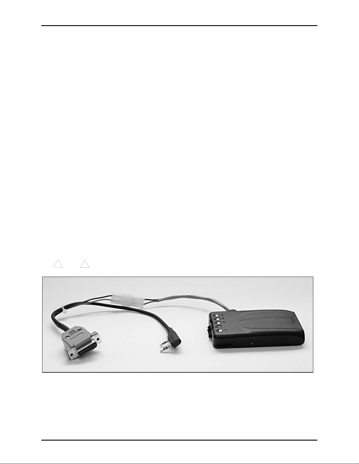
5. Connect the DB15 side of the interface cable to the RF control PCBA (located inside the front cover
of the call box). Plug the dual 2.5/3.5-mm audio plug into the socket of the Kenwood radio. Connect
the battery eliminator plug and the interface cable receptacle. See Figure 1.
!
Note
!
Observe polarity. Red to red and black to black.
Figure 1. Cable Assembly
\\s_eng\gtcproddocs\radio products-current release\43003\43003-044b\43003-044b.doc
02/07
Page 3

Pub. 43003-044B
ODEL 190-3170K RF CALL BOX ADAPTER KIT FOR KENWOOD 170 SERIES PORTABLE RADIO Page: 3 of 4
M
Figure 2. Models CB193-003, CB194-003, and CB195-003
\\s_eng\gtcproddocs\radio products-current release\43003\43003-044b\43003-044b.doc
02/07
Page 4

Pub. 43003-044B
ODEL 190-3170K RF CALL BOX ADAPTER KIT FOR KENWOOD 170 SERIES PORTABLE RADIO Page: 4 of 4
M
6. Dress cables as shown in Figure 3 to avoid signal interference.
Figure 3. Interior of the Call Box
7. Re-insert the front cover hinges into the rear section and close the cover, making certain to avoid
pinching wires between the cover and rear section. Tighten the four screws until the cover meets the
rear section.
\\s_eng\gtcproddocs\radio products-current release\43003\43003-044b\43003-044b.doc
02/07
 Loading...