

Page 1

Pub. 43003-045C
GAI-TRONICS® CORPORATION
A HUBBELL COMPANY
Model 190-002PS
Weatherproof Power Supply Kit
Field Installation Kit Instructions
Confidential ity Notice
This manual is provided solely as an operational, installation, and maintenance guide and contains
sensitive business and technical information which is confidential and proprietary to GAI-Tronics.
GAI-Tronics retains all intellectual property and other rights in or to the information contained herein,
and such information may only be used in connection with the operation of your GAI-Tronics product or
system. This manual may not be disclosed in any form, in whole or in part, directly or indirectly, to any
third party.
General Information
The Model 190-002PS Weatherproof Power Supply Kit includes the following components:
Qty Description
1 15 V dc power supply
1 Mounting bracket
1 2-gang electrical box
2 Mounting screws
1 Box cover and gasket
4 Tamper-resistant screws for cover
1 Conduit hub, ½-inch
1
1 Installation instructions
1 DC power cable harness
1 Tamper-proof Torx bit
½-inch × 3 inches galvanized conduit nipple
GAI-Tronics Corporation 400 E. Wyomissing Ave. Mohnton, PA 19540 USA
610-777-1374 800-492-1212 Fax: 610-796-5954
V
ISIT WWW.GAI-TRONICS.COM FOR PRODUCT LITERATURE AND MANUALS
Page 2
Pub. 43003-045C
Model 190-002PS Weatherproof Power Supply Kit Page: 2 of 3
Installation
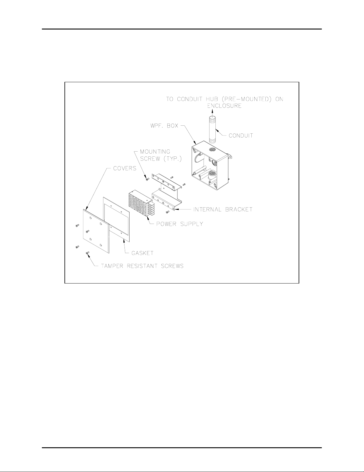
Refer to Figure 1 for installation details.
Figure 1. Power Supply Installation
Mounting
Addressable Amplified Speaker
Prior to mounting the spacer:
1. Remove conduit insert from bushing (white).
2. Attach conduit nipple to weatherproof conduit box.
3. Attach box/conduit nipple to the speaker bushing.
4. Install the power supply bracket and power supply in conduit box according to Figure 2.
5. Adjust the power supply output voltage to 15 V dc.
f:\radio products-current release\43003\43003-045c\43003-045c.doc
08/09
Page 3

Pub. 43003-045C
Model 190-002PS Weatherproof Power Supply Kit Page: 3 of 3
RF Call Box
Prior to mounting the RF call box:
1. Locate the dimple on the bottom right side of the call box enclosure (facing the front of the unit).
2. Drill 1/8-inch pilot hole in dimple, then carefully enlarge to 7/8 inch.
3. Attach the 1/2-inch conduit hub to call box enclosure making certain the gasket seals properly.
4. Attach conduit nipple to weatherproof conduit box.
5. Attach the box/conduit nipple to the conduit hub.
6. Install the power supply bracket and power supply in the conduit box according to Figure 2.
7. Adjust the power supply output voltage to 15 V dc.
Figure 2. Power Supply Wiring Connections
MPORTANT NOTE:
I
To properly charge the backup battery (if required), the 40404-060 power supply (included with
this kit) must be set for 15.0 V dc output. This output can be adjusted at the voltage adjustment
potentiometer labeled ADJ. Refer to Figure 2 for wire connections.
f:\radio products-current release\43003\43003-045c\43003-045c.doc
08/09
 Loading...