

Page 1

Pub. 42004-110A
GAI-TRONICS® CORPORATION
A HUBBELL COMPANY
Model 13411-001 (8-Ohm) and
13411-002 (16-Ohm)
Replacement Voice Coil/Diaphragm Assemblies
Confidentiality Notice
This manual is provided solely as an operational, installation, and maintenance guide and contains
sensitive business and technical information that is confidential and proprietary to GAI-Tronics. GAITronics retains all intellectual property and other rights in or to the information contained herein, and
such information may only be used in connection with the operation of your GAI-Tronics product or
system. This manual may not be disclosed in any form, in whole or in part, directly or indirectly, to any
third party.
General Information
The following driver assemblies are covered in this manual:
Model Description
13314-001 8-ohm, Div. 2 Hazardous
13314-002 16-ohm, Div. 2 Hazardous
13314-003 70-volt, Div. 2 Hazardous (16-ohm VC)
13314-004 100-volt, Div. 2 Hazardous (16-ohm VC)
13315-001 8-ohm, Div. 1 Hazardous
13315-002 16-ohm, Div. 1 Hazardous
13315-003 70-volt, Div. 1 Hazardous (16-ohm VC)
The equipment described below is listed by Underwriter’s Laboratories for use in the hazardous areas
described. This listing is contingent upon several points:
• Equipment is installed in accordance with the National Electrical Code and/or any special
instructions.
• No unauthorized mechanical or electrical modifications are made.
• The ac input power is disconnected from all associated equipment before removing equipment
covers.
• Replacement parts are equivalent to the original.
• All cover bolts and/or fittings removed for maintenance are replaced before reconnecting the ac
power.
GAI-Tronics Corporation 400 E. Wyomissing Ave. Mohnton, PA 19540 USA
610-777-1374 800-492-1212 Fax: 610-796-5954
ISIT WWW.GAI-TRONICS.COM FOR PRODUCT LITERATURE AND MANUALS
V
Page 2
Pub. 42004-110A
Model 13411-001 and 13411-002 Replacement Voice Coil/Diaphragm Assemblies Page:
2 of 3
Voice Coil Replacement for 13314 Series Dr ivers
1. Remove the three retaining screws from the back cover, and open the driver housing.
2. Firmly grasp wires leading to the connector tabs on the voice coil frame, and pull the leads straight
out.
3. Remove the two retaining screws from the bracket holding the magnet assembly in place, and
carefully withdraw the magnet assembly.
4. Replace the voice coil assembly, placing the new silicon gasket provided into the driver cavity first.
Discard the old gasket.
5. Check to see if any foreign material has entered the magnet assembly voice coil gap. See “Cleaning
the Magnetic Gap” section below.
6. Replace the magnet assembly, being careful not to crush the voice coil, and replace the bracket and
screws.
CAUTION
Do not over-tighten these screws. The recommended torque is 6–8 inch-
pounds. Tighten sequentially.
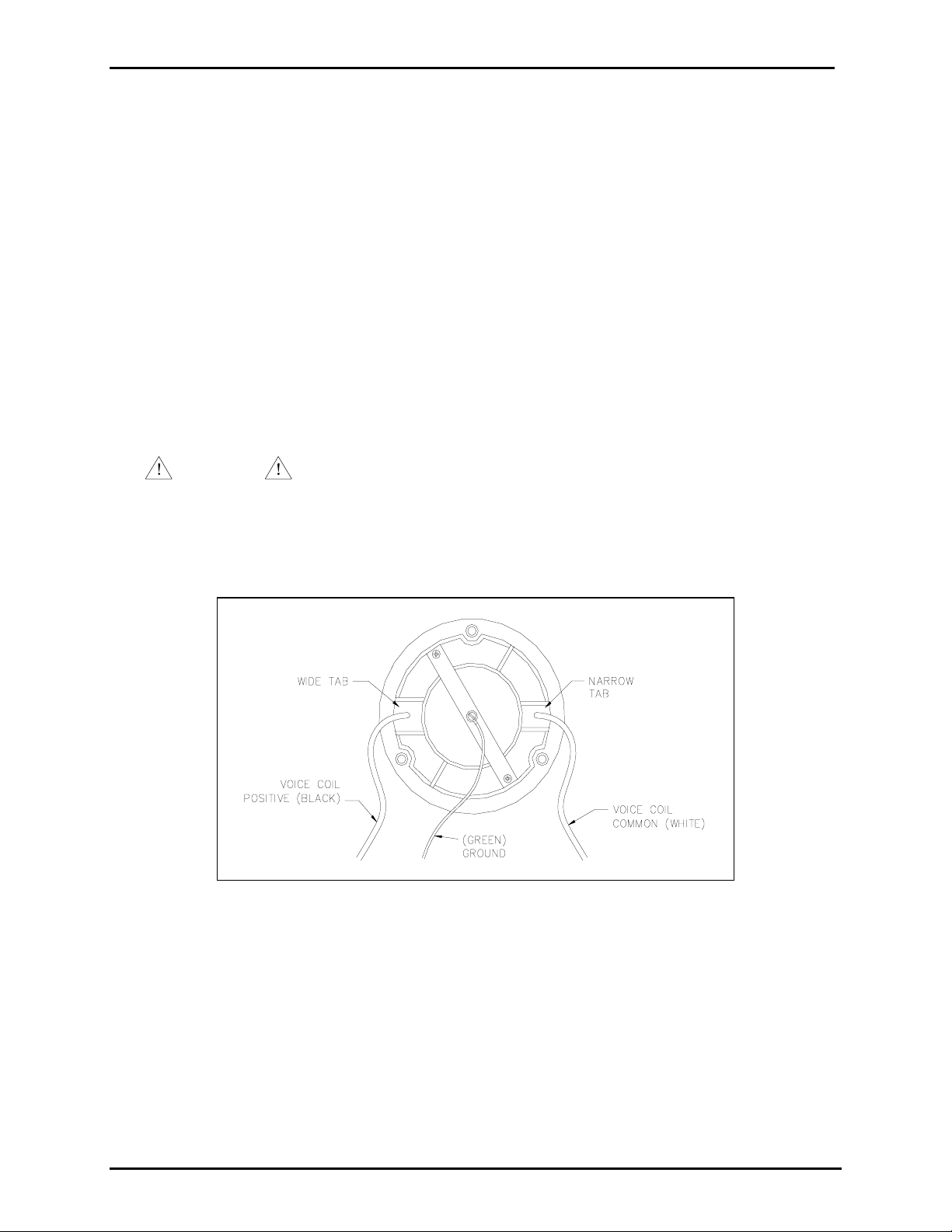
7. For Models 13314-001 and 13314-002, connect the black wire onto the wide tab connection of the
voice coil and the white wire to the narrow tab. See Figure 1 below.
Figure 1. Models 13314-001 and -002 Rear View with Cover Removed
8. For Model 13314-003, (the 70-volt driver with a transformer), and 13314-004 (the 100-volt driver
with a transformer), connect the gray wire to the wide tab and the blue wire to the narrow tab.
9. Replace the back cover using the new gasket provided, and reinstall the screws.
f:\standard ioms - current release\42004 instr. manuals\42004-110a.doc
5/11
Page 3

Pub. 42004-110A
Model 13411-001 and 13411-002 Replacement Voice Coil/Diaphragm Assemblies Page:
Voice Coil Replacement for 13315 Series Dr ivers
1. Remove the six flange bolts from the driver, and remove the rear housing.
3 of 3
CAUTION
Handle the castings with extreme care. The mating flange surfaces must
not be scratched, scored, or otherwise damaged.
2. For Model 13315-003, the 16-ohm with a 70-volt transformer, remove the wire nuts connecting the
transformer secondary to the voice coil leads.
3. Remove the three screws retaining the transformer mounting plate and remove the plate assembly.
4. Perform steps 3 through 6 in the “Voice Coil Replacement for 13314 Series Drivers” section.
5. Connect the black wire to the wide tab of the voice coil and the white wire to the narrow tab.
6. For Model 13315-003, bring the black and white wires through their associated clearance holes in the
transformer mounting plate, and reconnect the plate to the front housing.
7. Reconnect the gray wire from the transformer to the black voice coil lead and the blue transformer
common wire to the white voice coil lead using suitable splice connectors. See Figure 2 below.
8. Replace the rear housing cover and bolts. N
OTE: Bolts must be torqued to 40 foot-pounds (54.2
N-m).
Figure 2. 13315-003 Rear View with Cover Removed
Cleaning the Magnetic Gap
If any material (fillings, dust, etc.) is apparent in the magnetic gap, it may be easily cleaned using a small
piece of masking tape doubled over with its adhesive side out. Insert the tape end into the gap, and slide
it all the way around. Repeat this process until the masking tape comes out clean.
f:\standard ioms - current release\42004 instr. manuals\42004-110a.doc
5/11
Page 4

Warranty
Equipment. GAI-Tronics warrants for a period of one (1) year from the date of shipment, that any
GAI-Tronics equipment supplied hereunder shall be free of defects in material and workmanship, shall
comply with the then-current product specifications and product literature, and if applicable, shall be fit
for the purpose specified in the agreed-upon quotation or proposal document. If (a) Seller’s goods prove
to be defective in workmanship and/or material under normal and proper usage, or unfit for the purpose
specified and agreed upon, and (b) Buyer’s claim is made within the warranty period set forth above,
Buyer may return such goods to GAI-Tronics’ nearest depot repair facility, freight prepaid, at which time
they will be repaired or replaced, at Seller’s option, without charge to Buyer. Repair or replacement shall
be Buyer’s sole and exclusive remedy. The warranty period on any repaired or replacement equipment
shall be the greater of the ninety (90) day repair warranty or one (1) year from the date the original
equipment was shipped. In no event shall GAI-Tronics warranty obligations with respect to equipment
exceed 100% of the total cost of the equipment supplied hereunder. Buyer may also be entitled to the
manufacturer’s warranty on any third-party goods supplied by GAI-Tronics hereunder. The applicability
of any such third-party warranty will be determined by GAI-Tronics.
Services. Any services GAI-Tronics provides hereunder, whether directly or through subcontractors,
shall be performed in accordance with the standard of care with which such services are normally
provided in the industry. If the services fail to meet the applicable industry standard, GAI-Tronics will
re-perform such services at no cost to buyer to correct said deficiency to Company's satisfaction provided
any and all issues are identified prior to the demobilization of the Contractor’s personnel from the work
site. Re-performance of services shall be Buyer’s sole and exclusive remedy, and in no event shall GAITronics warranty obligations with respect to services exceed 100% of the total cost of the services
provided hereunder.
Warranty Periods. Every claim by Buyer alleging a defect in the goods and/or services provided
hereunder shall be deemed waived unless such claim is made in writing within the applicable warranty
periods as set forth above. Provided, however, that if the defect complained of is latent and not
discoverable within the above warranty periods, every claim arising on account of such latent defect shall
be deemed waived unless it is made in writing within a reasonable time after such latent defect is or
should have been discovered by Buyer.
Limitations / Exclusions. The warranties herein shall not apply to, and GAI-Tronics shall not be
responsible for, any damage to the goods or failure of the services supplied hereunder, to the extent
caused by Buyer’s neglect, failure to follow operational and maintenance procedures provided with the
equipment, or the use of technicians not specifically authorized by GAI-Tronics to maintain or service the
equipment. THE WARRANTIES AND REMEDIES CONTAINED HEREIN ARE IN LIEU OF AND
EXCLUDE ALL OTHER WARRANTIES AND REMEDIES, WHETHER EXPRESS OR IMPLIED BY
OPERATION OF LAW OR OTHERWISE, INCLUDING ANY WARRANTIES OF
MERCHANTABILITY OR FITNESS FOR A PARTICULAR PURPOSE.
Return Policy
If the equipment requires service, contact your Regional Service Center for a return authorization number
(RA#). Equipment should be shipped prepaid to GAI-Tronics with a return authorization number and a
purchase order number. If the equipment is under warranty, repairs or a replacement will be made in
accordance with the warranty policy set forth above. Please include a written explanation of all defects to
assist our technicians in their troubleshooting efforts.
Call 800-492-1212 (inside the USA) or 610-777-1374 (outside the USA) for help identifying the
Regional Service Center closest to you.
(Rev. 10/06)
Page 5

Warranty
Equipment. GAI-Tronics warrants for a period of one (1) year from the date of shipment, that any
GAI-Tronics equipment supplied hereunder shall be free of defects in material and workmanship, shall
comply with the then-current product specifications and product literature, and if applicable, shall be fit
for the purpose specified in the agreed-upon quotation or proposal document. If (a) Seller’s goods prove
to be defective in workmanship and/or material under normal and proper usage, or unfit for the purpose
specified and agreed upon, and (b) Buyer’s claim is made within the warranty period set forth above,
Buyer may return such goods to GAI-Tronics’ nearest depot repair facility, freight prepaid, at which time
they will be repaired or replaced, at Seller’s option, without charge to Buyer. Repair or replacement shall
be Buyer’s sole and exclusive remedy. The warranty period on any repaired or replacement equipment
shall be the greater of the ninety (90) day repair warranty or one (1) year from the date the original
equipment was shipped. In no event shall GAI-Tronics warranty obligations with respect to equipment
exceed 100% of the total cost of the equipment supplied hereunder. Buyer may also be entitled to the
manufacturer’s warranty on any third-party goods supplied by GAI-Tronics hereunder. The applicability
of any such third-party warranty will be determined by GAI-Tronics.
Services. Any services GAI-Tronics provides hereunder, whether directly or through subcontractors,
shall be performed in accordance with the standard of care with which such services are normally
provided in the industry. If the services fail to meet the applicable industry standard, GAI-Tronics will
re-perform such services at no cost to buyer to correct said deficiency to Company's satisfaction provided
any and all issues are identified prior to the demobilization of the Contractor’s personnel from the work
site. Re-performance of services shall be Buyer’s sole and exclusive remedy, and in no event shall GAITronics warranty obligations with respect to services exceed 100% of the total cost of the services
provided hereunder.
Warranty Periods. Every claim by Buyer alleging a defect in the goods and/or services provided
hereunder shall be deemed waived unless such claim is made in writing within the applicable warranty
periods as set forth above. Provided, however, that if the defect complained of is latent and not
discoverable within the above warranty periods, every claim arising on account of such latent defect shall
be deemed waived unless it is made in writing within a reasonable time after such latent defect is or
should have been discovered by Buyer.
Limitations / Exclusions. The warranties herein shall not apply to, and GAI-Tronics shall not be
responsible for, any damage to the goods or failure of the services supplied hereunder, to the extent
caused by Buyer’s neglect, failure to follow operational and maintenance procedures provided with the
equipment, or the use of technicians not specifically authorized by GAI-Tronics to maintain or service the
equipment. THE WARRANTIES AND REMEDIES CONTAINED HEREIN ARE IN LIEU OF AND
EXCLUDE ALL OTHER WARRANTIES AND REMEDIES, WHETHER EXPRESS OR IMPLIED BY
OPERATION OF LAW OR OTHERWISE, INCLUDING ANY WARRANTIES OF
MERCHANTABILITY OR FITNESS FOR A PARTICULAR PURPOSE.
Return Policy
If the equipment requires service, contact your Regional Service Center for a return authorization number
(RA#). Equipment should be shipped prepaid to GAI-Tronics with a return authorization number and a
purchase order number. If the equipment is under warranty, repairs or a replacement will be made in
accordance with the warranty policy set forth above. Please include a written explanation of all defects to
assist our technicians in their troubleshooting efforts.
Call 800-492-1212 (inside the USA) or 610-777-1374 (outside the USA) for help identifying the
Regional Service Center closest to you.
(Rev. 10/06)
 Loading...