

Page 1
Pub. 43004-034C
GAI-TRONICS® CORPORATION
A HUBBELL COMPANY
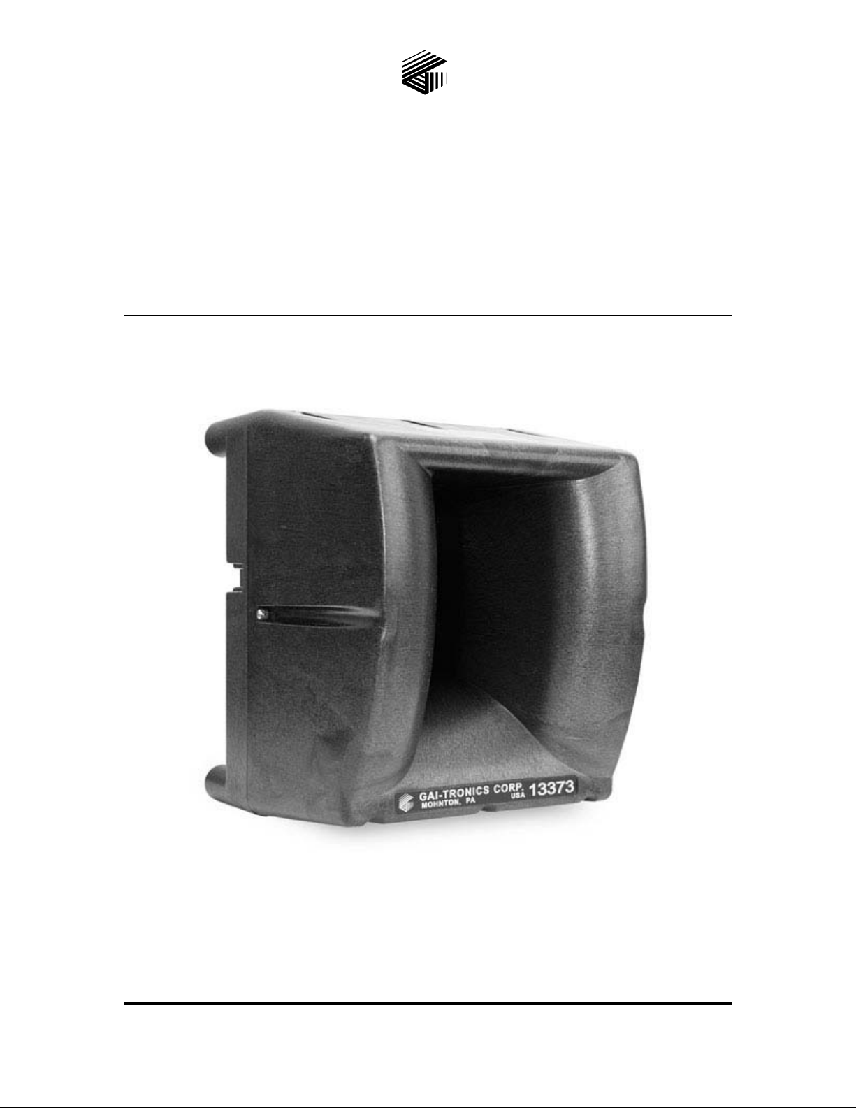
Model 13353, 13363 and 13373
Addressable Amplified Speakers
Installation and Operation Manual
GAI-Tronics Corporation 400 E. Wyomissing Ave. Mohnton, PA 19540 USA
610-777-1374 800-492-1212 Fax: 610-796-5954
V
ISIT WWW.GAI-TRONICS.COM FOR PRODUCT LITERATURE AND MANUALS
Page 2

Page 3

Pub.: 43004-034C
GAI-TRONICS® CORPORATION
A HUBBELL COMPANY
Model 13353, 13363 and 13373
Addressable Amplified Speakers
Installation and Operation Manual
T ABLE OF C ONTENTS
Foreword.........................................................................................................................................1
Scope of Manual......................................................................................................................................1
Nomenclature..........................................................................................................................................1
Ordering Replacement Parts.................................................................................................................1
Service and Repair.................................................................................................................................. 1
Confidentiality Notice............................................................................................................................. 2
FCC Licensing Information................................................................................................................... 2
Computer Software Copyrights.............................................................................................................3
Warranty ................................................................................................................................................. 3
Safety and General Information............................................................................................................4
Operational Cautions..............................................................................................................................5
Safe Handling of CMOS Integrated Circuit Devices...........................................................................6
Performance Specifications............................................................................................................7
General Information.......................................................................................................................9
Product Overview...................................................................................................................................9
Features....................................................................................................................................................9
Available Models.....................................................................................................................................9
Replacement Parts and Kits.................................................................................................................10
Programming Software and Cable......................................................................................................10
System Layout Considerations............................................................................................................11
Operating Modes...........................................................................................................................11
Generic Operation................................................................................................................................11
DTMF Selective Operation..................................................................................................................11
DTMF Selective with Manual Switch ................................................................................................................12
DTMF Selective with Voice Switch ...................................................................................................................12
Two-Tone Selective............................................................................................................................... 12
Feed-Thru Operation............................................................................................................................13
GAI-Tronics Corporation 400 E. Wyomissing Ave. Mohnton, PA 19540 USA
610-777-1374 800-492-1212 Fax: 610-796-5954
V
ISIT WWW.GAI-TRONICS.COM FOR PRODUCT LITERATURE AND MANUALS
Page 4

TABLE OF CONTENTS P UB. 43004-034C
Volume Adjustments.....................................................................................................................13
Remote Volume Adjustment................................................................................................................13
With Automatic Level Adjustment Disabled......................................................................................................13
With Automatic Level Adjustment Enabled.......................................................................................................14
Local Volume Adjustment ................................................................................................................... 14
Acoustic Feedback ................................................................................................................................ 14
Output Contact..............................................................................................................................15
Battery Monitor.............................................................................................................................15
Programming and Set Up.............................................................................................................15
Required Programming Accessories...................................................................................................16
Opening the Addressable Amplified Speaker ....................................................................................16
LED Indicators...................................................................................................................................... 16
Card Suite Software......................................................................................................................17
Installation.............................................................................................................................................17
Connecting the Programming Cable...................................................................................................17
Programming the Addressable Amplified Speaker...........................................................................18
Initial Setup and File Creation ............................................................................................................................18
Operating Modes.................................................................................................................................................20
RF Programming Software (required only for Models 13363 and 13373) ...................................... 32
Installation ..........................................................................................................................................................32
Connecting the Programming Cable...................................................................................................................32
Programming the Radio ...................................................................................................................................... 33
Installation ....................................................................................................................................36
Safety and General Information..........................................................................................................36
Outdoor Installation Product...............................................................................................................................36
Antenna Care ......................................................................................................................................................36
Electromagnetic Interference/Compatibility.......................................................................................................36
Mechanical Receipt Inspection............................................................................................................36
Cable Installation Safety Consider at ions............................................................................................36
Equipment Required............................................................................................................................37
Programming ......................................................................................................................................................37
Tools ...................................................................................................................................................................37
Mounting................................................................................................................................................37
Cable Installation.................................................................................................................................. 38
Power......................................................................................................................................................38
Wire Connections..................................................................................................................................39
Typical Connection Scenarios ............................................................................................................................40
12506-001 Remote Volume Control Wiring Instructions..................................................................43
Hardware Configuration..............................................................................................................44
Audio Line Termination Jumper ........................................................................................................ 44
Fuses.......................................................................................................................................................44
GAI-Tronics Corporation 400 E. Wyomissing Ave. Mohnton, PA 19540 USA
610-777-1374 800-492-1212 Fax: 610-796-5954
V
ISIT WWW.GAI-TRONICS.COM FOR PRODUCT LITERATURE AND MANUALS
Page 5

TABLE OF CONTENTS P UB. 43004-034C
Connectors.............................................................................................................................................45
TB1 Wiring Connector .......................................................................................................................................45
TB2 Wiring Connector .......................................................................................................................................45
Radio Connector Pin-out.....................................................................................................................................47
Terminal Strip Designations ...............................................................................................................................48
Field Installed Options..................................................................................................................48
Model SPK200 Solar Interface Kit...................................................................................................... 48
Model XB001 External Long-Life Battery Enclosure.......................................................................48
Model BB133 Battery Backup Kit.......................................................................................................49
Model 12506-001 Remote Volume Control Assembly.......................................................................49
Model 190-002PS Weatherproof Power Supply Kit..........................................................................49
Definitions and Acronyms............................................................................................................50
Appendix A: Speaker Zoning Example.......................................................................................51
GAI-Tronics Corporation 400 E. Wyomissing Ave. Mohnton, PA 19540 USA
610-777-1374 800-492-1212 Fax: 610-796-5954
V
ISIT WWW.GAI-TRONICS.COM FOR PRODUCT LITERATURE AND MANUALS
Page 6

Pub.: 43004-034C
GAI-TRONICS® CORPORATION
A HUBBELL COMPANY
Model 13353, 13363 and 13373
Addressable Amplified Speakers
Foreword
Scope of Manual
This manual offers descriptive data and service information for the Addressable Amplified Speaker
Assemblies.
Nomenclature
The model number, located on the nameplate on top of the speaker, specifically identifies GAI-Tronics
equipment.
Ordering Replacement Parts
When ordering replacement parts or requesting equipment information, please include the complete
identification number. This applies to all components, kits, and chassis. If the component part number is
not known, the order should include the number of the chassis or kit of which it is a part and sufficient
description of the desired component to identify it. Order parts from:
Customer Service
GAI-Tronics Corporation
400 E. Wyomissing Ave.
Mohnton, PA 19540
US: 800-492-1212
Outside US: 610-777-1374
Service and Re pair
Inoperative or malfunctioning equipment should be returned to the factory for repair. Please call
1-800-492-1212 or 610-777-1374 to obtain a Return Authorization number, published repair prices, and
shipping instructions.
OTE: A purchase order or credit card number is required prior to processing non-warranty repairs.
N
GAI-Tronics Corporation 400 E. Wyomissing Ave. Mohnton, PA 19540 USA
610-777-1374 800-492-1212 Fax: 610-796-5954
V
ISIT WWW.GAI-TRONICS.COM FOR PRODUCT LITERATURE AND MANUALS
Page 7

Pub. 43004-034C
Model 13353, 13363, and 13373 Addr es sabl e Amplified Speakers Page: 2 of 52
Confidentiality Notice
This manual is provided solely as an operational, installation, and maintenance guide and contains
sensitive business and technical information that is confidential and proprietary to GAI-Tronics.
GAI-Tronics retains all intellectual property and other rights in or to the information contained herein,
and such information may only be used in connection with the operation of your GAI-Tronics product or
system. This manual may not be disclosed in any form, in whole or in part, directly or indirectly, to any
third party.
FCC Licensing In formation
Your radio operates on General Mobile Radio Service (GMRS) frequencies and is subject to the Rules
and Regulations of the Federal Communications Commission (FCC). The FCC requires that all operators
using GMRS frequencies obtain a radio license before operating their equipment. To obtain the FCC
forms, go to http://wireless.fcc.gov/services/personal/generalmobile/index.html
159, which include all forms and instructions.
Changes or modifications not approved by GAI-Tronics Corporation may void the user’s authority
granted by the FCC to operate this radio and should not be made. To comply with FCC requirements,
transmitter adjustments should be made only by or under the supervision of a person certified as
technically qualified to perform transmitter maintenance and repairs in the private land mobile and fixed
services as certified by an organization representative of the user of those services. Replacement of any
transmitter component (crystal, semiconductor, etc.) not authorized by the FCC equipment authorization
for this radio could violate FCC rules.
to obtain Forms 605 and
OTE: Use of this radio outside the country where it was intended to be distributed is subject to
N
government regulations and may be prohibited.
Federal Communications Commission (FCC)
1-202-418-0177 1-800-418-FORM
1-800-418-3676
1-888-CALL-FCC
1-888-225-5322
Or: http://www.fcc.gov
f:\radio products-draft\gtc 43004\43004-034c\43004-034c.doc
05/10
Page 8

Pub. 43004-034C
Model 13353, 13363, and 13373 Addr es sabl e Amplified Speakers Page: 3 of 52
Computer Softw are Copyrights
This product contains copyrighted computer programs stored in semiconductor memory. These programs
are copyrighted by GAI-Tronics Corporation and may not be reproduced in any form without expressed
written permission from GAI-Tronics.
Warranty
GAI-Tronics warrants for a period of one (1) year from the date of shipment, that any GAI-Tronics equipment supplied hereunder
shall be free of defects in material and workmanship, shall comply with the then-current product specifications and product
literature, and if applicable, shall be fit for the purpose specified in the agreed-upon quotation or proposal document. If (a)
Seller’s goods prove to be defective in workmanship and/or material under normal and proper usage, or unfit for the purpose
specified and agreed upon, and (b) Buyer’s claim is made within the warranty period set forth above, Buyer may return such
goods to GAI-Tronics’ nearest depot repair facility, freight prepaid, at which time they will be repaired or replaced, at Seller’s
option, without charge to Buyer. Repair or replacement shall be Buyer’s sole and exclusive remedy, and the warranty period on
any repaired or replacement equipment shall be one (1) year from the date the original equipment was shipped. In no event shall
GAI-Tronics’ warranty obligations with respect to equipment exceed 100% of the total cost of the equipment supplied hereunder.
The applicability of any such third-party warranty will be determined solely by GAI-Tronics.
Services. Any services GAI-Tronics provides hereunder, whether directly or through subcontractors, shall be performed in
accordance with the standard of care with which such services are normally provided in the industry. If the services fail to meet
the applicable industry standard, GAI-Tronics will, for a period of one (1) year from the date of completion, re-perform such
services at no cost to the Buyer. Re-performance of services shall be Buyer’s sole and exclusive remedy, and in no event shall
GAI-Tronics’ warranty obligations with respect to services exceed 100% of the total cost of services provided hereunder.
Limitations/Exclusions. The warranty on any equipment supplied hereunder is subject to Customer’s use in compliance
with applicable FCC regulations and manufacturer specifications. The warranties herein shall not apply to, and GAI-Tronics
shall not be responsible for, any damage to the goods or failure of the services supplied hereunder, to the extent caused by
accident, misuse, abuse, neglect, system design, product modification, failure to follow instructions contained in the product
manual, repair, or attempted repair by anyone not authorized by GAI-Tronics, improper installation, installation of parts that do
not conform to the quality or specifications of the original parts or accessories, damage or loss occurred during shipment, or any
unit which is not new when sold or upon which the serial number has been defaced, modified or removed. The warranty does not
extend to damage incurred by natural causes including Force Majeure. The warranty does not cover microprocessors if failure is
due to static damage or application of improper voltage. THE WARRANTIES AND REMEDIES CONTAINED HEREIN ARE
IN LIEU OF AND EXCLUDE ALL OTHER WARRANTIES AND REMEDIES, WHETHER EXPRESS OR IMPLIED BY
OPERATION OF LAW OR OTHERWISE, INCLUDING ANY WARRANTIES OF MERCHANTABILITY OR FITNESS
FOR A PARTICULAR PURPOSE.
Operational and Maintenance Procedures. Buyer acknowledges that any improper use, maintenance, or
modification of the equipment provided hereunder, or use of unqualified maintenance or service technicians will severely impair
the operational effectiveness of the entire communication system. Buyer hereby agrees to indemnify, defend and hold GAITronics harmless from and against any and all third party claims arising, in any manner, out of: (a) Buyer’s neglect of the
equipment; (b) Buyer’s use of technicians not authorized by GAI-Tronics to service the equipment; or (c) Buyer’s improper use
or modification of the equipment or failure to follow the operational and maintenance procedures provided with the equipment.
Limitation of Liability/Damages. In no event (even should circumstances cause the exclusive warranties and remedies
set forth in the Warranty section to fail of their essential purpose) shall either party be liable for any indirect, incidental, special or
consequential damages (including, but not limited to, loss of use, loss of anticipated profits, or damages arising from delay)
whether such claims are alleged to have arisen out of breach of warranty, breach of contract, strict or absolute liability in tort, or
other act, error or omission, or from any other cause whatsoever, or any combination of the foregoing.
f:\radio products-draft\gtc 43004\43004-034c\43004-034c.doc
05/10
Page 9

Pub. 43004-034C
Model 13353, 13363, and 13373 Addr es sabl e Amplified Speakers Page: 4 of 52
Safety and General Inf ormation
Installation should only be performed by qualified service personnel in accordance with the
National Electrical Code or applicable local codes.
Power Sources - Operate this unit only from the type of power source indicated on the label. If
Outdoor Product:
Power Lines - An outdoor system should not be located in the vicinity of overhead power lines, electric
lights, or power circuits, or where it may contact such power lines or circuits, as this contact might be
fatal. Refer to the National Electrical Code Article 800 regarding installation.
unsure of the type of power supply to use, contact qualified service personnel.
• For units intended to operate from battery power, refer to operating instructions.
• For units intended to operate with External Power Supplies, use only the recommended
approved power supplies.
• For units intended to operate with a limited power source, this power source must comply
with EN60950. Substitutions may damage the unit or cause fire or shock.
User Instructions
This equipment has been tested and found to comply with the limits for a Class A digital device, pursuant
to part 15 of the FCC Rules. These limits are designed to provide reasonable protection against harmful
interference when the equipment is operated in a commercial environment. This equipment generates,
uses, and can radiate radio frequency energy and, if not installed and used in accordance with the
instruction manual, may cause harmful interference to radio communications. Operation of this
equipment in a residential area is likely to cause harmful interference in which case the user will be
required to correct the interference at his own expense.
Exposure to Radio Frequency Energy
Your radio is designed to comply with the following standards and guidelines regarding exposure of
human beings to radio frequency electromagnetic energy:
• FCC, Code of Federal Regulations; 47 CFR part 2 sub-part J
• American National Standards Institute (ANSI)/Institute of Electrical and Electronic Engineers (IEEE)
C95.1-1992
• Institute of Electrical and Electronic Engineers (IEEE) C95.1-1999 Edition
• International Commission on Non-Ionizing Radiation Protection (ICNIRP) 1998
• Ministry of Health (Canada) Safety Code 6. Limits of Human Exposure to Radio Frequency
Electromagnetic Fields in the Frequency Range from 3 kHz to 300 GHz, 1999
f:\radio products-draft\gtc 43004\43004-034c\43004-034c.doc
05/10
Page 10

Pub. 43004-034C
Model 13353, 13363, and 13373 Addr es sabl e Amplified Speakers Page: 5 of 52
Antenna Care
Unauthorized antennas, modifications, or attachments could damage the radio and may violate FCC
regulations.
Do NOT hold the antenna when the radio is IN USE. Holding the antenna affects the effective range.
Approved Accessories
Only use GAI-Tronics Corporation approved accessories. Please visit www.gai-tronics.com.
Electromagnetic Interference/Compatibility
Electronic equipment may be susceptible to electromagnetic interference. If you experience interference,
visit the FCC website at http://www.fcc.gov
for possible solutions.
Operational Cautions
Hospitals or Health Care Facilities
To avoid electromagnetic interference and/or compatibility conflicts, turn off your radio in any facility
where posted notices instruct you to do so. Hospital or health care facilities may be using equipment that
is sensitive to external RF energy.
Aircraft/Airports
Airports may be using equipment that is sensitive to external RF energy. Any use of a radio must be in
accordance with applicable regulations.
Medical Devices - Pacemakers
These recommendations are consistent with the independent research by, and recommendations of the
U.S. Food and Drug Administration. Persons with pacemakers should:
• ALWAYS keep the radio more than six inches (15 cm) from their pacemaker when the radio is turned
ON.
• Do NOT carry the radio in the breast pocket.
• Turn the radio OFF immediately if you have any reason to suspect that interference is taking place.
Blasting Caps and Areas
To avoid possible interference with blasting operations, turn off your radio when you are near electrical
blasting caps, in a blasting area, or in areas posted: “Turn off two-way radio.” Obey all signs and
instructions.
f:\radio products-draft\gtc 43004\43004-034c\43004-034c.doc
05/10
Page 11

Pub. 43004-034C
Model 13353, 13363, and 13373 Addr es sabl e Amplified Speakers Page: 6 of 52
Safe Handling of CMOS Integrated Circuit De vices
Many of the integrated circuit devices used in communications equipment are of the Complementary
Metal Oxide Semiconductor (CMOS) type. Because of their high open circuit impedance, CMOS
integrated circuits are vulnerable to damage from static charges. Care must be taken handling, shipping,
and servicing them and the assemblies in which they are used.
Even though protection devices are provided in CMOS integrated circuit inputs, the protection is effective
only against overvoltage in the hundreds of volts range such as is encountered in an operating system. In
a system, circuit elements distribute static charges and load the CMOS circuits, decreasing the chance of
damage. However, CMOS circuits can be damaged by improper handling of the modules, even in a
system.
To avoid damage to circuits, observe the following handling, shipping, and servicing precautions:
1. Prior to and while servicing a circuit module, particularly after moving within the service area,
momentarily touch both hands to a bare metal, earth-grounded surface. This will discharge any static
charge that may have accumulated on the person doing the servicing.
OTE: Wearing a conductive wrist strap will minimize static build-up during servicing.
N
2. Whenever possible, avoid touching any electrically conductive parts of the circuit module with your
hands.
3. Power down the unit before installing or removing the circuit module.
4. When servicing a circuit module, avoid carpeted areas, dry environments, and certain types of
clothing (silk, nylon, etc.) because they contribute to static build-up. Similarly, disconnect the test
probe prior to removing the ground lead.
5. All electrically powered test equipment should be grounded. Apply the ground lead from the test
equipment to the circuit module before connecting the test probe.
6. If a circuit module is removed from the system, it is desirable to lay it on a conductive surface (such
as a sheet of aluminum foil) which is connected to ground through 100 k of resistance.
7. When soldering, be sure the soldering iron is grounded and has a grounded tip.
8. Prior to connecting jumpers, replacing circuit components, or touching CMOS pins (if this becomes
necessary in the replacement of an integrated circuit device), be sure to discharge any static build-up
as described in procedure 1. Since voltage differences can exist across the human body, it is
recommended that only one hand be used if it is necessary to touch pins on the CMOS device and
associated board wiring.
9. When replacing a CMOS integrated circuit device, leave the device in its conductive rail container or
conductive foam until it is to be inserted into the printed circuit module.
10. All low impedance test equipment (such as pulse generators, etc.) should be connected to CMOS
device inputs after power is applied to the CMOS circuitry. Similarly, such low impedance
equipment should be disconnected before power is turned off.
11. Replacement modules shipped separately from the factory will be packaged in a conductive material.
Any modules being transported from one area to another should be wrapped in a similar material
(aluminum foil may be used). Never use non-conductive material for packaging these modules.
f:\radio products-draft\gtc 43004\43004-034c\43004-034c.doc
05/10
Page 12

Pub. 43004-034C
Model 13353, 13363, and 13373 Addr es sabl e Amplified Speakers Page: 7 of 52
Perf ormance Specifications
Electronic
Output power ................................................................................................ 4 mW to 8 W (default 16 mW)
Current draw @ full output (8 watts)................................................................................................... 1 amp
Sound pressure level ...................................................................................... 107 dB SPL, 1 watt at 1 meter
Nominal coverage when surface-mounted to wall (ref. –6 dB)
Vertical....................................................................................................................................... Upward: 40º
Downward: 60º
Horizontal ................................................................................................................................................. 90º
600 Ω audio input level............................................................................................................... 775 mVrms
Audio speaker volume adjustment range.............................................................................. 83–116 dB SPL
Audio speaker volume ...................................... Factory set @ nominal 89 dB SPL at a distance of 1 meter
Frequency response..................................................................................................... 450–3000 Hz +/-5 dB
Power Requirements
Model 40419-013 Power Supply (Included)
Input voltage ......................................................................................................... 100 to 240 V ac/50/60 Hz
Output voltage ................................................................................................................................... 15 V dc
Rated output current......................................................................................................................... 1.6 amps
Rated output power........................................................................................................................... 24 watts
Accessory Power Options
Model BB133 Battery Back-up Kit
Voltage............................................................................................................................................... 12 V dc
Capacity .............................................................................................................................................. 2.8 Ah
Battery life ............................................................................................................120 minutes at full output
Model XB001 External Long-Life Battery Kit (with 40201-008 battery)
Voltage............................................................................................................................................... 12 V dc
Capacity ............................................................................................................................................... 18 Ah
Battery life .................................................................................................................. 13 hours at full output
Model 190-002PS Kit (Includes 40404-060 DC Power Supply)
Output voltage (adjustable).................................. 13.2–15.0 V dc (Set to 15.0 V for battery trickle charge)
Rated output current......................................................................................................................... 2.1 amps
Rated output power........................................................................................................................... 25 watts
Input voltage ............................................................................................................ 85–264 V ac, 50–60 Hz
Input current................................................................................................ 0.7 A/115 V ac; 0.4 A/230 V ac
Solar panel output (at charge controller module)
Voltage (trickle charge) ..................................................................................................................... 12 V dc
f:\radio products-draft\gtc 43004\43004-034c\43004-034c.doc
05/10
Page 13

Pub. 43004-034C
Model 13353, 13363, and 13373 Addr es sabl e Amplified Speakers Page: 8 of 52
Mechanical
Physical dimensions............................................................................................... 8.02 × 8.12 × 9.52 inches
Enclosure material ..................................................................... Glass-reinforced polyester, 0.20 inch thick
Hardware..................................................................................... Urethane gaskets, stainless steel hardware
Color ..................................................................................................................................................... Black
Shipping weights
Model 13353..................................................................................................................................6.6 lbs.
Model 13363 /13373 .....................................................................................................................7.3 lbs.
Environmental
Temperature range .............................................................................................................. -20° C to +60° C
Weatherproof rating....................................................................................................................... Rainproof
Humidity ...................................................................................................................... 95% non-condensing
RF Receiver Module (Models 13363 /13373 only)
General
Frequency range............................................................................................................ VHF: 154–174 MHz
UHF: 450–470 MHz
Antenna impedance................................................................................................................................ 50 Ω
Operating voltage.............................................................................................. 9–18 V dc, 12 V dc nominal
Decoder................................................................................................................................ CTCSS/CDCSS
N
OTE: Receiver measurement procedures made per ANSI/TIA/EIA-603
Sensitivity (12 dB SINAD) ............................................................................................................... 0.25 µV
Inter-modulation ................................................................................................................................... 60 dB
Spurious response ................................................................................................................................. 55 dB
Audio output ............................................................................................................................... 900 mVrms
3.5 kHz deviated signal
Approvals
FCC Identifier.............................................................................................................. VHF: AIERT 17-142
UHF: AIERT 17-442
FCC Compliance................................................................................................................................. Part 90
VHF Antenna
Dimensions ........................................................................................................ Maximum 3.00 inches high
Mounting............................................................................................................................... BNC connector
Impedance.............................................................................................................................................. 50 Ω
UHF Antenna
Dimensions ........................................................................................................ Maximum 3.00 inches high
Mounting............................................................................................................................... BNC connector
Impedance.............................................................................................................................................. 50 Ω
f:\radio products-draft\gtc 43004\43004-034c\43004-034c.doc
05/10
Page 14
Pub. 43004-034C
Model 13353, 13363, and 13373 Addr es sabl e Amplified Speakers Page: 9 of 52
General Information
Product Overview
The GAI-Tronics Model 13353, 13363 and 13373 Addressable Amplified Speaker Assemblies are
designed for remote paging in temporary or permanent applications such as campuses, public gathering
locations, construction sites, or amusement parks.
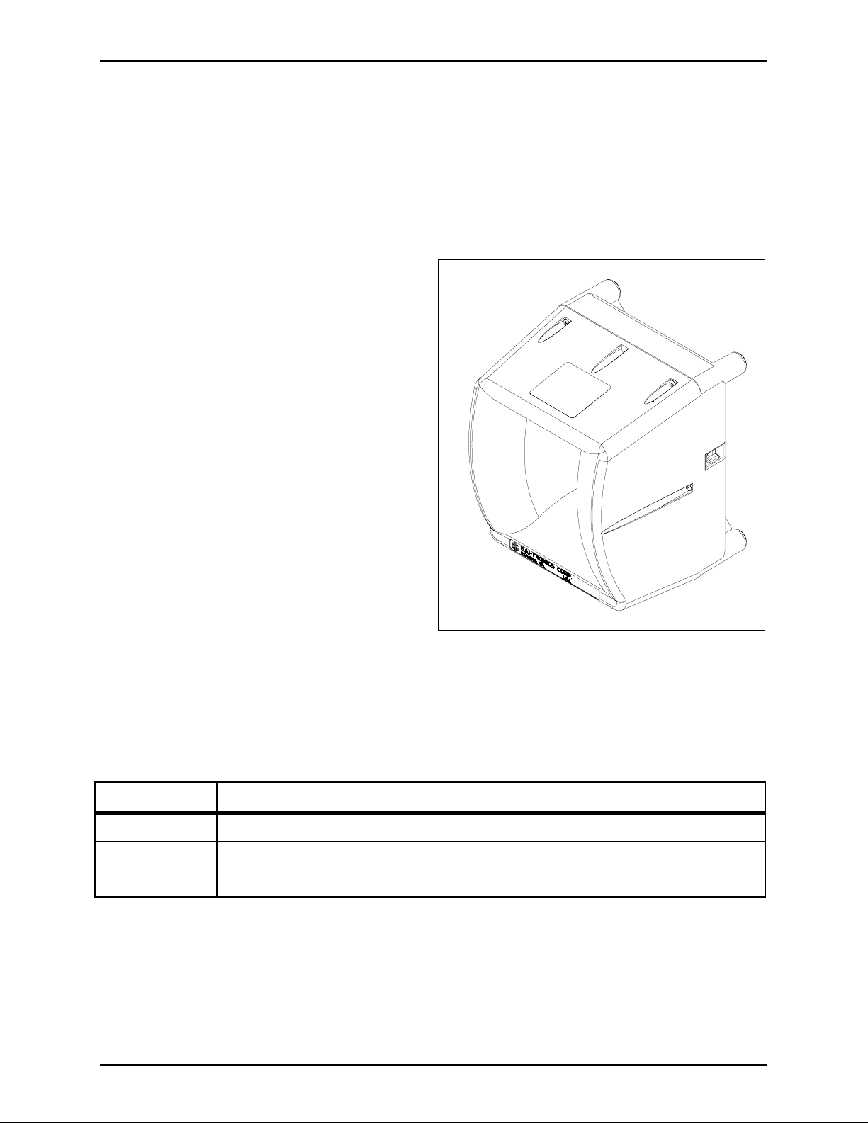
Fea tures
• Hardwired (600-ohm) and RF audio delivery
to speaker amplifier.
• One-way public address broadcasts.
• A high-efficiency (>80%) Class D amplifier
to provide up to 8 watts into an 8-ohm load
(116 dB SPL, measured at 1 meter on axis).
• Generic Operation - (common broadcast)
using input contact closure.
• Selective Operation - addressability for
individual unit, group/zone, or system-wide
broadcasts using DTMF or 2-Tone signaling
access.
• Remote volume control using DTMF
signaling.
• Automatic Level Adjustment automatically
adjusts volume during varying levels of
ambient noise.
• Universal ac input power supply provided.
• Battery trickle charge during normal operation
(battery optional).
• Programmable output control for strobe activation.
• PC programmable using the CARD Suite Programming Software Application.
Figure 1. Addressable Amplified Speaker Assembly
Available Mode ls
Part No. Description
13353 Hardwired 600-ohm audio input
13363 Hardwired 600-ohm input and/or VHF radio receiver input (154–174 MHz)
13373 Hardwired 600-ohm input and/or UHF radio receiver input (450–470 MHz)
f:\radio products-draft\gtc 43004\43004-034c\43004-034c.doc
05/10
Page 15
Pub. 43004-034C
Model 13353, 13363, and 13373 Addressable Amplified Speakers Page: 10 of 52
Replacem ent Parts and Kits
Part No. Description 13353 13363 13373
61512-029 Wiring Harness, Weatherproof Amplified Speaker
13327-021 Speaker
19101-022 VHF Radio, 154–174 MHz
19101-023 UHF Radio, 450–470 MHz
19502-007 VHF Antenna, 150–162 MHz
19502-009 UHF Antenna, 432–468 MHz
61213-008 Cable, DB15 male to 8-pin (RF module to PCBA)
69834-101 PCBA, Weatherproof Amplified Speaker
BB133 Battery Backup Kit
40201-010 Repl. Battery, 2.8 Ah, 12 V dc (included in BB133)
XB001 External Weatherproof Long-life Battery Enclosure
40201-008 Battery, 18 Ah, 12 V dc for XB001
SPK200 Solar Power Interface Kit
12506-001 Remote Volume Control L-Pad
GTRFP7784
Solar Panel Array, 30-Watt
-108
190-002PS
Weatherproof 15 V dc Power Supply Kit,
85–265 V ac, 50/60 Hz
40408-009 Battery Charger for 40201-010
40408-011 Battery Charger for 40201-008
51809-019 3A SloBlo Fuse
GTRFP6432-
Free Standing Tripod
006
TPD001 Tripod Mounting Kit
40419-013 Universal Input AC Power Supply
Programming Software and Cable
Part No. Descripti on 13353 13363 13373
19101-024 RF Module Programming Kit (software & cable)
XAC1000A CARD Suite Programming Software CD
XAC0004A Programming Cable (for speaker)
f:\radio products-draft\gtc 43004\43004-034c\43004-034c.doc
05/10
Page 16

Pub. 43004-034C
Model 13353, 13363, and 13373 Addressable Amplified Speakers Page: 11 of 52
System Layout C onsiderations
The installer must consider the system layout to assure proper audio delivery to the Addressable
Amplified Speakers.
• For hardwired installations, each speaker requires a balanced 600-ohm, 0 dBm input audio signal. A
contact closure may be required depending on the selected operating mode. Cabling (telephone cable,
cat-5/6, etc.) must be distributed appropriately to attain the necessary audio level and balance. Audio
distribution apparatus may be necessary to accomplish this task.
• For RF installations, each speaker must be located within line of site of the RF transmitting device
(repeater, base, or mobile radio).
Operating Mode s
The Addressable Amplified Speakers can operate in three different modes, Generic, DTMF Selective,
and
Two-Tone Selective. The mode of operation determines if the speakers will broadcast all audio
transmissions or only “selective” audio transmissions. Each operating mode is described in the following
sections.
Generic Operation
Generic Mode requires an external control input to activate (wake up) the Addressable Amplified
Speaker. Once active, the unit will broadcast any audio received from the transmitting device. Removal
of the activation input returns the speaker to the inactive (sleep) mode.
• For hardwired installations, the control input activation must be in the form of a voltage–free (dry)
contact closure.
• For RF installations, the control input activation is provided from the “RF carrier detect” control
circuit of the integral radio receiver. This simply means that audio (carrier) must be received on the
appropriately programmed radio frequency and PL code.
All Addressable Amplified Speakers are factory programmed for Generic Operation.
DTMF Selectiv e Operation
Selective operation allows “addressable” access to each Addressable Amplified Speaker using DTMF
signaling (DTMF Selective) or Two-Tone signaling (Two-Tone Selective). Each speaker can be
programmed with up to eight different addresses. Upon receiving a valid DTMF or Two-Tone code, the
speaker becomes active and will broadcast any audio received from the transmitting device. The speaker
returns to the inactive (sleep) mode when the transmission is complete and a pre-programmed hold time
expires.
f:\radio products-draft\gtc 43004\43004-034c\43004-034c.doc
05/10
Page 17

Pub. 43004-034C
Model 13353, 13363, and 13373 Addressable Amplified Speakers Page: 12 of 52
By assigning a combination of addresses to each Addressable Amplified Speaker, the overall system can
be segregated into multiple broadcast zones. In a typical multi-zone system, three access codes might be
assigned to each module.
• Address 1 – is always a unique address assigned to only that addressable amplified speaker. By using
this access code, an individual addressable amplified speaker is activated.
• Address 2 – could be an address assigned to a group of addressable amplified speakers located in the
same speaker broadcast area. When received, the group of Addressable Amplified Speakers is
activated simultaneously. This access method is used when an audio broadcast is required to a
particular broadcast zone.
• Address 3 – could be an address assigned to all Addressable Amplified Speakers in the system. By
using this access code, all speakers are activated simultaneously when a system-wide audio broadcast
is required.
DTMF Selective with Manual Switch
This mode is typically used in an RF application or in a hardwired application requiring additional
security to prevent unauthorized access. The DTMF Selective with Manual Switch mode requires an
external control input to activate (wake up) the Addressable Amplified Speaker. Once active, the unit
must receive a valid DTMF address. Upon receiving a valid address, the speaker will broadcast any audio
received from the transmitting device. Removal of the activation input returns the speaker to the inactive
(sleep) mode.
• For RF installations (Models 13363 & 13373), the control input activation is provided from the RF
carrier detect control circuit of the integral radio receiver. This simply means that audio (carrier)
must be received on the appropriately programmed radio frequency and PL code and the appropriate
DTMF address must be received.
• For hardwired installations (Model 13353), the control input activation must be in the form of a
voltage–free (dry) contact closure (additional wire pair).
GAI-Tronics CARD Suite Programming Software is used to assign the operating mode and DTMF
addresses. Valid DTMF addresses can contain two to eight digits followed by the “#” symbol. DTMF
digits 0-9 and A, B, C, and D are permitted.
DTMF Selective with Voice Switch
This mode is used for hardwired installation where a contact closure is not available from the transmitting
device. In this case, the Addressable Amplified Speaker constantly monitors the audio line for a valid
DTMF address. Upon receiving a valid address, the speaker will broadcast any subsequent audio
received from the transmitting device. The speaker returns to the inactive (sleep) mode after audio from
the transmitting device stops for a programmable amount of time.
Two-T one Selective
GAI-Tronics CARD Suite Programming Software can also be used to assign Two-Tone access codes
instead of DTMF access codes. Valid access codes contain two frequencies in the 400–2700 Hz range.
Each Addressable Amplified Speaker can be programmed with up to eight different codes. By assigning
a combination of access codes to each device, the overall system can be segregated into different speaker
broadcast zones as described above for DTMF signaling. Two-Tone signaling is only applicable for RF
installations. Contact the Service Center at 1-800-492-1212 for instructions in using CARD Suite to
program Two-Tone Selective operation.
f:\radio products-draft\gtc 43004\43004-034c\43004-034c.doc
05/10
Page 18

Pub. 43004-034C
Model 13353, 13363, and 13373 Addressable Amplified Speakers Page: 13 of 52
Feed -Thru Operation
The Addressable Amplified Speaker can be programmed to perform as a Lead unit or as a Slave unit in a
speaker grouping. This function is referred to as “Feed-Thru” operation and can be activated via the
CARD Suite Programming Software. This operation is primarily used in an RF installation and allows
the Lead Addressable Amplified Speaker to receive the source audio signal via the RF airwaves and
provide hardwired, 600-ohm redistribution of the audio (and page control, if required) to one or more
speakers within a grouping. This configuration could greatly reduce system costs by limiting the number
of RF speakers required.
When in Individual operation, the Lead speaker simply acts as a receiving point for the Slave speaker(s),
allowing the Slave speaker(s) to be addressed individually without activation of the Lead or other Slaves.
When in Follow-me operation, the Slave speaker(s) will activate upon activation of the Lead speaker.
This access includes adjusting volume control settings.
Refer to page 26 for detailed information.
V olume Adjustments
Each speaker assembly’s output volume can be adjusted via four different methods:
• Remotely, using DTMF signaling
• Programmed prior to installation using CARD Suite
• Locally using the optional Model 12506-001 L-pad
• Automatically, utilizing the ALA (Automatic Level Adjustment) feature. This feature would be used
if steady high noise levels sometimes occur but are not present continuously.
Remote V olume Adjustment
With Automatic Level Adjustment Disabled
To adjust the speaker output volume with the Addressable Amplified Speaker programmed for DTMF
selective operation, begin a broadcast using the speaker’s local address (Address 1) followed by a “#”
symbol. When the speaker becomes “active”, transmit a DTMF “*” symbol. Upon receiving the “*”, the
speaker will broadcast a test tone for a programmable amount of time. During this tone, transmit a “*” to
increase the volume or transmit a “#” to decrease the volume. Each press of the “*” will increase the
volume one level and each press of the “#” will decrease the volume one level. The speaker will
broadcast a test tone at the new volume level each time it is changed. Volume can be increased or
decreased between minimum and maximum in 11 steps. A low frequency warning will be broadcast
when the volume has reached either its upper or lower volume limit.
If the speaker under test is programmed for Generic Operation, it will have provisions for programming a
DTMF volume control address via the CARD Suite Programming Software. When properly
programmed, the speaker can be accessed for volume control by simply transmitting its volume control
address and changing the volume as described in the previous paragraph.
CARD Suite includes a test tone duration setting that is programmable between .5 and 6.0 seconds in .5
second increments. This test tone will automatically extinguish at the end of the pre-programmed
duration time or can be manually extinguished by sending a DTMF digit other than “*” or “#.” The
speaker stores its volume setting when the test tone ends.
f:\radio products-draft\gtc 43004\43004-034c\43004-034c.doc
05/10
Page 19

Pub. 43004-034C
Model 13353, 13363, and 13373 Addressable Amplified Speakers Page: 14 of 52
With Automatic Level Adjustment Enabled
The Automatic Level Adjustment (ALA) allows the speaker to automatically adjust its output to broadcast
at a pre-programmed level above the average ambient noise. Usually an offset of 10 dB is appropriate.
The speaker calculates the average ambient noise level every 5 seconds while it is not broadcasting. The
output level is then adjusted to compensate for the background noise. The first update to the calculated
ambient level will be at most 10 seconds after the standby time expires at the end of a broadcast.
Four settings are available for the ALA feature; Disabled, 5 dB Offset, 10 dB Offset, and 15 dB Offset.
To activate the ALA feature, select one of the three offset levels. The Offset Level is the level of audio
(in dB SPL) above the average ambient noise level, at which the speaker will broadcast.
With ALA enabled, the speaker will adjust its output, based on the steady background noise level in the
vicinity of the speaker, to some level between its maximum output (8 watts) and a programmed minimum
output level. To set this minimum output level, use CARD Suite or adjust the level remotely as described
in the previous section (ALA Disabled). As the background noise level decreases, the speaker output will
also decrease, but the speaker output will not drop below this minimum programmed setting, even when
the background noise drops to a very low level. This setting in CARD Suite is labeled as “Min. Volume
Level.”
Local V olume Adjust ment
Local Volume Adjustment is achievable through the use of an L-pad volume control connected to the
speaker assembly (Model 12506-001). No test tone is generated during this adjustment as the user must
generate audio for this test while adjusting the L-pad.
This is a passive adjustment. The maximum output level is defined by the CARD Suite program. Since
the Local Volume Adjustment can only adjust the output level lower than the maximum programmed
level, it is recommended that the Addressable Amplified Speaker is programmed for maximum volume
level (8 watts).
Do not connect an L-pad if the Automatic Level Adjustm ent is enabl ed as the automatic adjust men t
may be ineffective.
Acoustic F eedback
An audio broadcast command originating too close to an installed speaker (such as from telephones or
portable radios) may create acoustic feedback, depending on the volume level setting of the speaker. To
prevent feedback from occurring, originating distance from the speaker and orientation to the speaker (do
not position in front of the speaker) should be considered.
If the originating position with respect to the speaker’s location requires close proximity, the speaker can
be muted via a “shutdown” closure input. The shutdown closure input could be from a handset
hookswitch, relay, or other similar device.
f:\radio products-draft\gtc 43004\43004-034c\43004-034c.doc
05/10
Page 20

Pub. 43004-034C
Model 13353, 13363, and 13373 Addressable Amplified Speakers Page: 15 of 52
Output Contact
The Addressable Amplified Speaker is capable of providing a low current output contact designed for
activating a GAI-Tronics Model 530-001 Strobe or other peripheral devices. The Output Contact
Function and its associated Hold Time are programmable via the CARD Suite Software Application and
can be enabled on all or selected DTMF addresses when in DTMF Selective mode. It is also available for
use in Generic mode. If enabled, the contact will activate when the speaker assembly begins to broadcast
audio. The contact will be deactivated either at the end of the audio broadcast (within a few seconds) or
after a selectable Hold Time (if applicable). Hold time can be programmed from 1 second to 30 minutes.
The output contact can be configured as either Normally Open or Normally Closed.
The output contact’s maximum current capability is 100 mA. To use with loads requiring higher current,
an interposing control relay will be required between the speaker assembly’s output contact and the actual
device.
OTE: The output contact will remain in the “open” state when unit power is removed.
N
Battery Monitor
If the installed Addressable Amplified Speaker utilizes either the BB133 Battery Backup Kit or the
XB001/40201-008 Long-life Battery (usually used in solar power configuration), the speaker assembly
can be programmed to generate an alert tone when the battery charge falls below the factory-set limit.
Using CARD Suite, enable the Battery Checking feature under the Low Battery Alert section. The
volume of the Low Battery Alert Tone can be adjusted to one of three settings; 50%, 75%, or 100% of the
speaker volume setting. The alert tone will sound every four minutes (factory default setting) until the
battery is charged to a level above the Low Battery Alarm Limit.
OTE: To avoid hearing an alert tone during initial power up after installation (assuming Battery
N
Checking has been selected in CARD Suite), it is recommended that the battery be fully charged prior to
installation. Battery charger No. 40408-009 can be used for the BB133 Kit (2.8 Ah) and charger No.
40408-011 can be used for the 40201-008 Battery (18 Ah). If a backup or long-life battery is not
installed, keep this Battery Checking feature disabled (factory default setting).
Programming and Set Up
The Addressable Amplified Speaker requires software configuration to set the operating parameters. It is
highly recommended to program and bench-test the unit prior to field installation.
A computer with a COM port (RS-232) and Windows95 or newer operating system is required to
program the Addressable Amplified Speaker. Windows NT operating system is not supported. If the PC
contains only USB ports, a USB–to–RS-232 converter is also required. Programming accessories are
sold separately. They are as described below:
The No. XAC1000A CARD Suite Programming Software (Version 4.3.0 or newer) and No. XAC0004A
programming cable are used to program the operating parameters of all Addressable Amplified Speaker
models.
The Model 13363 and 13373 RF Addressable Amplified Speakers also require the radio receiver to be
programmed. The No. 19101-024 RF Programming Kit includes the software and cable for programming
the desired frequency and optional PL code into the radio receiver.
f:\radio products-draft\gtc 43004\43004-034c\43004-034c.doc
05/10
Page 21

Pub. 43004-034C
Model 13353, 13363, and 13373 Addressable Amplified Speakers Page: 16 of 52
Required Programming Accessori es
Part No. Description
XAC1000A CARD Suite Programming Software CD - Version 4.3.0 or newer (needed for all models)
XAC0004A Programming Cable (needed for all models)
19101-024 RF Module Programming Kit (needed for Models 13363 and 13373 only) consists of:
• Ritron DTX L-Series Programming CD
• 9/RTC-PAS Cable
• DTXP-PAC Cable Adaptor
• 2147C001 9-pin to 25-pin Sub D Adaptor
Opening the Addressable Amplified Speaker
The Addressable Amplified Speaker must be opened for programming and installation. Remove the
speaker from the carton and position on a flat surface with the front of the speaker facing up. Although
the front section attaches to the rear section with six Phillips screws, only two screws have been secured
during the production process. Back out the two screws on the left and right side of the speaker. All
screws are captive and will remain in the front section. Lift the front section straight up and flip to the
left-hand side of the rear section. Refer to Figure 2.
Figure 2. Addressable Amplified Speaker.
LED Indica tors
Two LED indicators are located on the speaker amplifier PCBA, but are visible only when the module is
opened. The Power LED is activated when the unit is powered. The Programming LED indicates when
the unit is properly connected to a programming computer using CARD Suite Programming Software.
Refer to Figure 18 on page 44 and Figure 19 on page 46 for LED locations.
f:\radio products-draft\gtc 43004\43004-034c\43004-034c.doc
05/10
Page 22

Pub. 43004-034C
Model 13353, 13363, and 13373 Addressable Amplified Speakers Page: 17 of 52
Card Suite Software
Installa tion
Exit all other programs that are running until the installation is complete.
Place the CD in the computer CD-ROM drive. If the “auto-run” feature on your CD-ROM drive is
enabled, the CARD Suite menu screen should appear within a few seconds.
If the installation does not start up automatically, it can be run from the Start menu. Select the Start
button; then select Run. At the prompt, type x:\Setup.exe where x represents the drive letter that is
associated with your CD-ROM drive. A CARD Suite icon should appear on the desktop display after
successful installation.
Connecting t he Programming Cable
1. Attach the programming cable to an available COM serial port connector on the computer using the
9-pin adaptor supplied with the cable (CARD Suite supports COM1–COM8).
N
OTE: If using a USB–to–RS-232 converter, connect the converter to the computer’s USB port and
then connect the programming cable to the 9-pin mating receptacle on the converter.
2. After opening the Addressable Amplified Speaker (as previously described), plug the programming
cable into the programming connector J1 on the speaker amplifier PCBA. Refer to Figure 18 on page
44 or Figure 19 on page 46.
3. Connect a 12–15 V dc power source to the terminal block labeled BATTERY, located on the front
section of the Addressable Amplified Speaker assembly or connect the 12–15 V dc power supply
provided with the speaker and plug into a 120 V ac source. Be sure to observe the voltage polarity in
both cases. Failure to observe polarity will result in circuit damage.
4. Verify the Programming LED illuminates on the speaker amplifier PCBA. The LED is located next
to the J1 programming connector. This illumination verifies the unit is under power and the computer
and programming cable are connected properly.
f:\radio products-draft\gtc 43004\43004-034c\43004-034c.doc
05/10
Page 23

Pub. 43004-034C
Model 13353, 13363, and 13373 Addressable Amplified Speakers Page: 18 of 52
Programming the Addressable Amplified Speaker
Initial Setup and File Creation
Run the CARD Suite Programming Software on the PC. The following screen will appear:
Select the Addressable Amplified Speaker icon on the left pane of the screen.
Any existing speaker archives that are stored in CARD Suite on this PC are shown in the pane on the
right side of the screen. These archives can be modified by double-clicking the archive entry in the right
pane.
To add a new speaker archive, select File Æ New Archive from the tool bar as shown below. One
archive is required for each Addressable Amplified Speaker in the system, if DTMF or Two-Tone
Selective are programmed. A common archive can be used for speakers programmed in Generic mode.
f:\radio products-draft\gtc 43004\43004-034c\43004-034c.doc
05/10
Page 24

Pub. 43004-034C
Model 13353, 13363, and 13373 Addressable Amplified Speakers Page: 19 of 52
The following screen will be displayed when adding a new archive:
1. Enter an Archive Description
for the paging module archive as shown above. The description is
generally the device’s location within the end-user’s facility or a tag number identification assigned
by the system installer.
2. Enter the Customer/Site description. This is generally the facility name. This entry is useful when
managing speakers at multiple facilities. It will allow the system administrator to easily sort the
speaker entries when making changes or updates to the speaker programming.
3. Select the archive creation Method using the radio buttons. To upload an existing configuration
from the connected speaker, select Create new unit
archive by reading connected unit.
When programming an older series Addressable Amplified Speaker (Models 13352, 13362, 13372)
using Card Suite Version 4.2.0 or newer, a new archive should be created only by first reading the
connected speaker. Using the default values setting will display programming features that do not
exist in old series models.
If a speaker is not connected or the programmer wants to create a new archive starting with default
values, select: Create new unit archive using default values.
4. Select OK. The archive will be created and then opened for editing. (The “reading connected unit”
creation requires about 15 seconds.)
f:\radio products-draft\gtc 43004\43004-034c\43004-034c.doc
05/10
Page 25

Pub. 43004-034C
Model 13353, 13363, and 13373 Addressable Amplified Speakers Page: 20 of 52
5. The following screen will be displayed when the archive (new or existing) is opened. Enter a name or
initials in Last Modified By field (optional). This is a method to track programming changes by
date and user.
6. Select the Configuration tab to display the main Configuration screen where the majority of the
Addressable Amplified Speaker operation parameters are set.
Operating Modes
Select the Operation Mode from the pull-down menu. The screen will change appearance based on the
selection made. Each selection is shown in the following screen shots.
Generic Mode
f:\radio products-draft\gtc 43004\43004-034c\43004-034c.doc
05/10
Page 26

Pub. 43004-034C
Model 13353, 13363, and 13373 Addressable Amplified Speakers Page: 21 of 52
Volume Level – Select the speaker output level using the slide bar. The valid range is 4 mW to 8 W in
doubling increments (4 mW, 8 mW, 16 mW, etc.).
Automatic Level Adjust – Enable this feature if steady high noise is sometimes present near the
speaker, but is not present continuously. With the ALA feature disabled, the speaker output volume will
follow the exact level setting on the volume control slide. This feature is enabled by selecting one of the
three available offset levels; 5 dB Offset, 10 dB Offset, or 15 dB Offset. The Offset Level is the level of
audio (measured as dB SPL) above the average ambient noise level, at which the speaker will broadcast.
The maximum audio output power attainable, with or without ALA enabled, is 8 watts.
OTE: ALA can be used in a Feed-Thru configuration. If the Addressable Amplified Speakers are
N
programmed for Follow-Me operation, the Lead speaker will be programmed for ALA functionality and
the Slave speakers will not. They will follow the level of the Lead speaker. If the Addressable Amplified
Speakers are programmed for Individual operation, both the Lead and the Slave speakers operate
independently and each can be programmed for ALA functionality.
Volume Adjust Address – Enter the DTMF Address code to be used for making volume changes from
a remote touch-tone device. The address should be a code unique to the unit being programmed. This
address code may include digits 0–9 as well as the extended DTMF digits A, B, C, and D. It can contain
two to eight digits. By using one or more of the DTMF digits A, B, C, or D, broadcast access will be
restricted to equipment capable of generating these DTMF digits, providing additional access security.
Test Tone Duration Adjust – The speaker will generate a tone at the current volume setting when it
enters the test tone mode (volume control). This entry starts the duration of the test tone. When the
volume is adjusted (in test tone mode), the speaker will generate a tone at the newly selected level. The
test tone duration’s valid range is 0.5–6.0 seconds in 0.5-second increments with a default setting of 3.0
seconds.
Output Contact – These settings control the activation of the Addressable Amplified Speaker’s contact
closure output. The settings are in effect only when the paging module is activated. Use the pull-down
menu to make one of the following selections:
• No Change – The output contact will be unaffected when the corresponding DTMF address is
received.
• Activate – The output contact will change state when the input control contact is received and the
module becomes active. The output contact returns to the normal state when the input contact opens.
• Activate + Hold – The output contact will change state when the input control contact is received.
The output contact returns to the normal state after the input contact opens and the Hold Time
duration expires.
Use the slide bar to set the Hold Time. Valid range is 1 second to 30 minutes.
Using the radio button, select the normal state of the relay contact with power applied to the paging
module. When power is removed, the contact will always be in the OPEN state.
• Normally Open – relay contact is OPEN when the unit is inactive and CLOSED when active.
• Normally Closed – relay contact is CLOSED when the unit is inactive and OPEN when active.
f:\radio products-draft\gtc 43004\43004-034c\43004-034c.doc
05/10
Page 27

Pub. 43004-034C
Model 13353, 13363, and 13373 Addressable Amplified Speakers Page: 22 of 52
Low Battery Alert
• Battery Checking – Select this checkbox to set the unit to test the battery voltage (default is every
4 minutes). If the battery voltage is low when the battery test occurs, the unit will broadcast a short
alert tone. The factory default “low battery” threshold is 11.5 V. If a backup battery is not connected
to the Paging Module, do not enable the Battery Checking.
• Alert Tone Volume – Selects the volume of the “low” alert tone as a fraction of the unit’s speaker
output level (50%, 75% or 100%). The factory default setting is 50%.
DTMF with Manual Switch Mode
Volume Level – Select the speaker output level using the slide bar. The valid range is 4 mW to 8 W in
doubling increments (4 mW, 8 mW, 16 mW, etc.).
Automatic Level Adjust – Enable this feature if steady high noise is sometimes present near the
speaker, but is not present continuously. With the ALA feature disabled, the speaker output volume will
follow the exact level setting on the volume control slide. This feature is enabled by selecting one of the
three available offset levels; 5 dB Offset, 10 dB Offset, or 15 dB Offset. The Offset Level is the level of
audio (measured as dB SPL) above the average ambient noise level, at which the speaker will broadcast.
The maximum audio output power attainable, with or without ALA enabled, is 8 watts.
OTE: ALA can be used in a Feed-Thru configuration. If the Addressable Amplified Speakers are
N
programmed for Follow-Me operation, the Lead speaker will be programmed for ALA functionality and
the Slave speakers will not. They will follow the level of the Lead speaker. If the Addressable Amplified
Speakers are programmed for Individual Operation, both the Lead and the Slave speakers operate
independently and each can be programmed for ALA functionality.
f:\radio products-draft\gtc 43004\43004-034c\43004-034c.doc
05/10
Page 28

Pub. 43004-034C
Model 13353, 13363, and 13373 Addressable Amplified Speakers Page: 23 of 52
Test Tone Duration Adjust – The speaker will generate a tone at the current volume setting when it
enters the test tone mode (volume control). This entry starts the duration of the test tone. When the
volume is adjusted (in test tone mode), the speaker will generate a tone at the newly selected level. The
test tone duration’s valid range is 0.5–6.0 seconds in 0.5-second increments with a default setting of 3.0
seconds.
DTMF Address & Description 1–8
Enter the DTMF addresses required to activate the Addressable Amplified Speaker. A description of up
to 12 characters can be entered for each address. Each address can contain two to eight digits. The “#”
symbol is automatically inserted into the address by the programming software and is not a required
programmable entry. Up to eight different addresses can be programmed.
Address 1 is always a unique address assigned only to the Addressable Amplified Speaker being
programmed. It is used for individual speaker access, and speaker volume control using additional
DTMF commands. Refer to Volume Adjustment section.
Addresses 2 through 8 are typically assigned to groups of speakers to create broadcast groups or zones
throughout the system. Addressable Amplified Speakers assigned to the same group or zone address will
activate simultaneously when that address is received.
A typical programming scenario is to use one address for individual access, two to six addresses for zone
access, and one address for system-wide (all-call) access. The all-call address would be programmed into
every paging module.
Each address code may include digits 0–9, as well as the extended DTMF digits A, B, C, D. It can
contain up to eight digits. By using one or more of the DTMF digits A, B, C, or D, broadcast access will
be restricted to equipment capable of generating these extended DTMF digits, providing greater access
security.
Output Contact Function
These settings control the activation of the Addressable Amplified Speaker’s contact closure output for
each DTMF address. The settings are in effect only when the specific DTMF address is received. Use
the pull-down menu to make one of the following selections:
• No Change – The output contact will be unaffected when the corresponding DTMF address is
received.
• Activate – The output contact will change state when the corresponding DTMF address is received.
The output contact returns to the normal state when the Standby Time duration (3 seconds) expires.
• Activate + Hold Time – The output contact will change state when the corresponding DTMF address
is received. The output contact returns to the normal state when the Standby Time and the Hold Time
durations expire.
• De-Activate – If active, the relay will reset to its normal state immediately after receiving the
corresponding DTMF address. This is a function used to override the Standby Time and Hold Time
assigned to other DTMF addresses.
Use the slide bar to set the Hold Time. Valid range is 1 second to 30 minutes.
In the Output Contact section at the bottom of the screen, select the normal state of the relay contact.
This will be the relay state when power is applied to the Addressable Amplified Speaker. When power is
removed, the contact will always be in the OPEN state.
• Normally Open – Relay contact is OPEN when the unit is inactive and CLOSED when active.
f:\radio products-draft\gtc 43004\43004-034c\43004-034c.doc
05/10
Page 29

Pub. 43004-034C
Model 13353, 13363, and 13373 Addressable Amplified Speakers Page: 24 of 52
• Normally Closed - Relay contact is CLOSED when the unit is inactive and OPEN when active.
Low Battery Alert
• Battery Checking – Select this checkbox to set the unit to test the battery voltage (default is every
4 minutes). If the battery voltage is low when the battery test occurs, the unit will broadcast a short
alert tone. The factory default “low battery” threshold is 11.5 V. If a backup battery is not connected
to the Paging Module, do not enable the Battery Checking.
• Alert Tone Volume – Selects the volume of the “low” alert tone as a fraction of the unit’s speaker
output level (50%, 75% or 100%). The factory default setting is 50%.
DTMF with Voice Switch Mode
Volume Level – Select the speaker output level using the slide bar. The valid range is 4 mW to 8 W in
doubling increments (4 mW, 8 mW, 16 mW, etc.).
Automatic Level Adjust – Enable this feature if steady high noise is sometimes present near the
speaker, but is not present continuously. With the ALA feature disabled, the speaker output volume will
follow the exact level setting on the volume control slide. This feature is enabled by selecting one of the
three available offset levels; 5 dB Offset, 10 dB Offset, or 15 dB Offset. The Offset Level is the level of
audio (measured as dB SPL) above the average ambient noise level, at which the speaker will broadcast.
The maximum audio output power attainable, with or without ALA enabled, is 8 watts.
f:\radio products-draft\gtc 43004\43004-034c\43004-034c.doc
05/10
Page 30

Pub. 43004-034C
Model 13353, 13363, and 13373 Addressable Amplified Speakers Page: 25 of 52
NOTE: ALA can be used in a Feed-Thru configuration. If the Addressable Amplified Speakers are
programmed for Follow-Me operation, the Lead speaker will be programmed for ALA functionality and
the Slave speakers will not. They will follow the level of the Lead speaker. If the Addressable Amplified
Speakers are programmed for Individual Operation, both the Lead and the Slave speakers operate
independently and each can be programmed for ALA functionality.
Test Tone Duration Adjust – The speaker will generate a tone at the current volume setting when it
enters the test tone mode (volume control). This entry starts the duration of the test tone. When the
volume is adjusted (in test tone mode), the speaker will generate a tone at the newly selected level. The
test tone duration’s valid range is 0.5–6.0 seconds in 0.5-second increments with a default setting of 3.0
seconds.
Voice Switch – Select the silence limit using the slide bar. The unit will return to inactive (sleep) mode
if audio is not received in this amount of time. The valid range is 3–10.5 seconds in 0.5 second
increments.
DTMF Address & Description 1–8
Enter the DTMF addresses required to activate the Addressable Amplified Speaker. A description of up
to 12 characters can be entered for each address. Each address can contain two to eight digits. The “#”
symbol is automatically inserted into the address by the programming software and is not a required
programmable entry. Up to eight different addresses can be programmed.
Address 1 is always a unique address assigned only to the Addressable Amplified Speaker being
programmed. It is used for individual speaker access, and speaker volume control using additional
DTMF commands. Refer to Volume Adjustment section.
Addresses 2 through 8 are typically assigned to groups of speakers to create broadcast groups or zones
throughout the system. Addressable Amplified Speakers assigned to the same group or zone address will
activate simultaneously when that address is received.
A typical programming scenario is to use one address for individual access, two to six addresses for zone
access, and one address for system-wide (all-call) access. The all-call address would be programmed into
every Addressable Amplified Speaker.
Each address code may include digits 0–9, as well as the extended DTMF digits A, B, C, D. It can
contain up to eight digits. By using one or more of the DTMF digits A, B, C, or D, broadcast access will
be restricted to equipment capable of generating these extended DTMF digits, providing greater access
security.
f:\radio products-draft\gtc 43004\43004-034c\43004-034c.doc
05/10
Page 31

Pub. 43004-034C
Model 13353, 13363, and 13373 Addressable Amplified Speakers Page: 26 of 52
Output Contact Function
These settings control the activation of the Addressable Amplified Speaker’s contact closure output for
each DTMF address. The settings are in effect only when the specific DTMF address is received. Use
the pull-down menu to make one of the following selections:
• No Change – The output contact will be unaffected when the corresponding DTMF address is
received.
• Activate – The output contact will change state when the corresponding DTMF address is received.
The output contact returns to the normal state when the Standby Time duration (3 seconds) expires.
• Activate + Hold Time – The output contact will change state when the corresponding DTMF address
is received. The output contact returns to the normal state when the Standby Time and the Hold Time
durations expire.
• De-Activate – If active, the relay will reset to its normal state immediately after receiving the
corresponding DTMF address. This is a function used to override the Standby Time and Hold Time
assigned to other DTMF addresses.
Use the slide bar to set the Hold Time. Valid range is 1 second to 30 minutes.
In the Output Contact section at the bottom of the screen, select the normal state of the relay contact.
This will be the relay state when power is applied to the Addressable Amplified Speaker. When power is
removed, the contact will always be in the OPEN state.
• Normally Open – Relay contact is OPEN when the unit is inactive and CLOSED when active.
• Normally Closed - Relay contact is CLOSED when the unit is inactive and OPEN when active.
Low Battery Alert
• Battery Checking – Select this checkbox to set the unit to test the battery voltage (default is every
4 minutes). If the battery voltage is low when the battery test occurs, the unit will broadcast a short
alert tone. The factory default “low battery” threshold is 11.5 V. If a backup battery is not connected
to the Paging Module, do not enable the Battery Checking.
• Alert Tone Volume – Selects the volume of the “low” alert tone as a fraction of the unit’s speaker
output level (50%, 75% or 100%). The factory default setting is 50%.
Feed Thru Operation
As previously stated, the Addressable Amplified Speaker can be programmed to allow a single speaker to
perform as a Lead unit or as a Slave unit within a speaker grouping. This is particularly useful and most
commonly used in an RF to hardwire transition. It allows an RF controlled speaker to serve as a Lead
unit with one or more 600-ohm speaker(s) hardwired to it as “Slaves”. Each speaker must be specifically
programmed to perform its function within the group. There are two basic modes of operation; FollowMe or Individual. The desired operation will determine the CARD Suite settings.
Follow-Me Operation
Follow-Me operation instructs all Slave speakers to track the exact functionality of the Lead speaker.
This allows a single DTMF or Two-Tone address received at the RF speaker to activate all speakers
within a grouping. This grouping could be considered a zone, building, floor, or some other specific yet
common area. In this operating mode, all slave speakers must be connected to the Lead speaker or
another Slave speaker via an audio pair and a control pair (two twisted pairs between speakers), as
indicated in Figure 3.
f:\radio products-draft\gtc 43004\43004-034c\43004-034c.doc
05/10
Page 32

Pub. 43004-034C
Model 13353, 13363, and 13373 Addressable Amplified Speakers Page: 27 of 52
Figure 3.
The Lead speaker can be programmed for either Generic or Selective (DTMF or Two-Tone) mode of
operation. However, the Slave speaker(s) must
speaker volume must
be programmed for maximum volume as shown in the following screen. In Follow-
be programmed for Generic operating mode and their
Me mode, adjusting the volume of the Lead speaker will also adjust the volume of the Slave speaker(s).
The control pair is required to activate each Slave speaker.
f:\radio products-draft\gtc 43004\43004-034c\43004-034c.doc
05/10
Page 33

Pub. 43004-034C
Model 13353, 13363, and 13373 Addressable Amplified Speakers Page: 28 of 52
Additional programming for Follow-Me operation is required under the CARD Suite Advanced tab. To
view the Advanced Tab, access an existing or create a new archive. While in the archive, select the
General tab and move the mouse cursor over the image of the speaker/stanchion module and right click
while pressing the Ctrl key. The Advanced tab will appear as shown below.
Move mouse cursor
over this image and
right click while
pressing the CTRL key.
In the Advanced Tab screen, locate the Secondary Audio Output section. The Enable Volume
Level Tracking box must be selected for the Lead speaker only. Additionally, the Page Output
Contact Follows Broadcast Audio box must be checked. This configuration is noted on the
following screen.
f:\radio products-draft\gtc 43004\43004-034c\43004-034c.doc
05/10
Page 34

Pub. 43004-034C
Model 13353, 13363, and 13373 Addressable Amplified Speakers Page: 29 of 52
Lead Speaker/Follow-Thru Operation
If only a single Slave speaker is connected to the Lead speaker in Follow-Me operation, both check boxes
in the Secondary Audio Output section of the Slave should remain unselected (default setting). If
multiple Slave speakers are connected to each other, as indicated in Figure 3, each Slave speaker must
have the Audio Feed Thru box selected and the Page Output Contact Follows Broadcast Audio
box must be checked, as indicated in the following screen.
NOTES:
1. The Page Output Contact Follows Broadcast Audio box is to be checked (enabled) only in
Follow-Me operation and when a downstream slave speaker is connected (Lead or Slave speaker
programming).
2. The Enable Volume Level Tracking and Audio Feed Thru boxes under Secondary Audio
Output are mutually exclusive. This means that only one can be enabled (checked) at a time. To
switch between the two boxes requires the checked box to be un-checked (disabled) first.
3. The Default Reset button in the lower right-hand corner of the Advanced screen, when pressed, will
reset all values on that screen to the factory default settings.
f:\radio products-draft\gtc 43004\43004-034c\43004-034c.doc
05/10
Page 35

Pub. 43004-034C
Model 13353, 13363, and 13373 Addressable Amplified Speakers Page: 30 of 52
Slave Speaker/Follow-Thru Operation
Selecting the Audio Feed Thru box in a Slave speaker allows the scaled audio of the Lead unit’s
speaker to be passed through to each connected Slave speaker, keeping all speakers within the grouping at
the same audio level. Even though this audio is connected from one speaker to the next, it is perceived
that the audio from the Lead speaker is sent to each Slave speaker directly. This concept is depicted in
Figure 4.
f:\radio products-draft\gtc 43004\43004-034c\43004-034c.doc
05/10
Figure 4.
Page 36

Pub. 43004-034C
Model 13353, 13363, and 13373 Addressable Amplified Speakers Page: 31 of 52
Individual Operation
Individual operation allows each 600-ohm Slave speaker to be accessed via its own dedicated address,
even though it is electrically connected to a Lead RF speaker. This configuration allows the use of the
lower cost Model 13353 600-Ohm Speaker but still allows each speaker to be programmed and addressed
separately from all other interconnected speakers. This approach would typically be used for buildings
with limited RF access or to simply reduce project costs. This operation allows the use of a single audio
pair between the Slave and Lead speaker and between each Slave speaker. No control pair is required
because each speaker will be activated when an appropriate DTMF or Two-Tone code is received. See
Figure 5.
Figure 5.
Individual operation requires that both the Lead speaker and the Slave speaker(s) are programmed with
the Audio Feed Thru box enabled on the Advance screen, as previously shown. Individual operation
allows the volume of each speaker to be adjusted independently. See page 13.
Individual operation allows the source audio received at the Lead speaker to be duplicated or passed
through to the next speaker. This same signal is then passed through from one Slave speaker to the next,
allowing each one to be activated individually without activation of the other connected speakers. They
may also be activated as a group if they are programmed with the same DTMF or Two-Tone address.
This concept is depicted in Figure 6.
f:\radio products-draft\gtc 43004\43004-034c\43004-034c.doc
05/10
Figure 6.
Page 37

Pub. 43004-034C
Model 13353, 13363, and 13373 Addressable Amplified Speakers Page: 32 of 52
RF Programming Software (required only for Models 13 363 and
13373)
Installation
Exit all other programs that are running until the installation is complete.
Place the CD in the computer CD-ROM drive. If the “auto-run” feature on your CD-ROM drive is
enabled, the Ritron DTXL_PCPS set-up screen should appear within a few seconds.
If the installation does not start up automatically, it can be run from the Start menu. Select the Start
button; then select Run. At the prompt, type x:\fscommand\setup.exe where x represents the drive
letter that is associated with your CD-ROM drive. A DTXL_PCPS icon should appear on the desktop
display after successful installation.
Connecting the Programming Cable
1. Unplug the Addressable Amplified Speaker’s 15-pin D-connector from the radio.
2. Connect the DTXP-PAC cable assembly’s 15-pin D-connector into the radio.
3. Connect the RJ11-style plug of the 9/RTC-PAS cable into the mating receptacle on DTXP-PAC
cable.
4. Connect the DB-9 to DB-25 adaptor to the other end of the 9/RTC-PAS cable.
5. Connect the DB-9 connector of the cable assembly to the computer serial port.
OTE: If using a USB–to–RS-232 converter, connect the converter to the computer’s USB port and
N
then connect the cable to the 9-pin mating receptacle on the converter.
6. Connect the red and black leads of the DTXP-PAC cable to a 12–15 V dc source (battery or power
supply), observing the polarity (red +, black-).
f:\radio products-draft\gtc 43004\43004-034c\43004-034c.doc
05/10
Page 38

Pub. 43004-034C
Model 13353, 13363, and 13373 Addressable Amplified Speakers Page: 33 of 52
Programming the Radio
1. Make sure the radio to be programmed is powered and connected to the PC (as described above)
before starting the programming software on the PC.
OTE: If the Ritron software does not read the type of the connected radio, unplug the programming
N
cable and re-insert.
2. The radio’s current programming will be displayed. Below is an example:
OTE: The RF Module is capable of being programmed for channels 1–8; however, the
N
Addressable Amplified Speaker uses only the frequency programmed for channel 8. Be sure to
program channel 8 with the licensed frequency.
f:\radio products-draft\gtc 43004\43004-034c\43004-034c.doc
05/10
Page 39

Pub. 43004-034C
Model 13353, 13363, and 13373 Addressable Amplified Speakers Page: 34 of 52
3. Enter the Receive (Rx) frequency into channel 8. This is the only frequency that must be
programmed. To enter the frequency, select channel 8 then the Edit button on the left to display the
following screen:
4. Enter the Rx Frequency, and select a Quiet Call (QC) frequency (TPL) or Digital Quiet Call
(DQC) code (DPL), if desired.
f:\radio products-draft\gtc 43004\43004-034c\43004-034c.doc
05/10
Page 40

Pub. 43004-034C
Model 13353, 13363, and 13373 Addressable Amplified Speakers Page: 35 of 52
5. After entering the frequency and optional QC or DQC, program the radio by selecting Radio >
Program Radio from the tool bar.
6. After the radio is programmed (time bar will disappear), disconnect the programming cable and
reconnect the DB-15 cable from the speaker amplifier PCBA.
f:\radio products-draft\gtc 43004\43004-034c\43004-034c.doc
05/10
Page 41

Pub. 43004-034C
Model 13353, 13363, and 13373 Addressable Amplified Speakers Page: 36 of 52
Installation
Safety and General Inf ormation
Installation should only be performed by qualified service personnel in accordance with the National
Electrical Code or applicable local codes.
Read, follow, and retain instructions – All safety and operating instructions should be read and followed
before operating the unit. Retain instructions for future reference.
Heed warnings – Adhere to all warnings on the unit and in the operating instructions.
Attachments – Attachments not recommended by the product manufacturer should not be used, as they
may cause hazards.
Servicing – Do not attempt to service this unit by yourself. Opening or removing covers may expose you
to dangerous voltage or other hazards. Refer all servicing to qualified service personnel.
This permanently connected apparatus must have an ALL-POLE MAINS switch with a contact separation
of at least 3mm in each pole incorporated in the electrical installation of the building.
Outdoor Installation Product
Power lines - An outdoor system should not be located in the vicinity of overhead power lines, electric
lights, or power circuits, where it may contact such power lines or circuits, as this contact might be fatal.
Refer to the National Electrical Code Article 800 regarding installation.
Antenna Care
Unauthorized antennas, modifications, or attachments could damage the radio and may violate FCC
regulations.
Electromagnetic Interference/Compatibility
Electronic equipment may be susceptible to electromagnetic interference. If you experience interference,
visit the FCC website at http://www.fcc.gov for possible solutions.
Mechanical Receipt Inspection
The Addressable Amplified Speaker is shipped in a cardboard container, protected from movement and
distress by a self-forming packaging material. Thoroughly inspect it as soon as possible after delivery.
In-transit damage should be immediately reported to the transportation company.
Cable Installation Safety Considerations
Interconnecting, communications, and Class 2 dc power cables should be separated from electrical light
or other Class 1 circuits by at least 2 inches. The exception is where Class 1 wiring or power circuits are
run in a raceway, or are metal-sheathed or metal-clad, or are permanently separated from the conductors
of the other circuitry by a continuous and firmly fixed nonconductor such as porcelain tubes or flexible
tubing in addition to the insulation on the wire. Communications cables and in-building wiring should be
listed and marked for the purpose according to NEC Article 800.
f:\radio products-draft\gtc 43004\43004-034c\43004-034c.doc
05/10
Page 42

Pub. 43004-034C
Model 13353, 13363, and 13373 Addressable Amplified Speakers Page: 37 of 52
Equipment Required
Programming
• PC with Windows 95 or newer operating system.
N
OTE: CARD Suite is not compatible with Windows NT.
• XAC1000A Programming Software (all models)
• XAC0004A Programming Cable (all models)
• 19101-024 RF Programming Kit (Models 13363 and 13373 only)
Tools
• #1 Phillips screwdriver
• 1/16-inch flat blade screwdriver (for TB101, TB1 and TB2 connections only)
Mounting
1. Open the Addressable Amplified Speaker as explained on page 16.
2. After opening the Addressable Amplified Speaker, untwist the nylon tie used for wire management.
Unplug the quick-connect fastons from the speaker and unplug the dual 7-point connectors (TB1) and
dual 3-point connectors (TB2) from the PCBA. The front section can now be completely separated
from the rear section. See Figure 7.
3. Mount the rear section to any flat surface using 1/4-inch diameter customer-provided screws in each
of the four 0.280-inch mounting holes in the corners of the rear section. Refer to Figure 7 for
mounting hole pattern dimensions. A Model 231-001 Pole Mounting Kit can also be used for pole or
surface mounting. Two customer-provided mounting screws are required to surface mount this kit.
The kit includes four mounting screws needed to secure the speaker to the kit’s bracket.
f:\radio products-draft\gtc 43004\43004-034c\43004-034c.doc
05/10
Figure 7. Mounting Detail
Page 43

Pub. 43004-034C
Model 13353, 13363, and 13373 Addressable Amplified Speakers Page: 38 of 52
Cable Installation
Each of the speaker assemblies is designed for bottom cable entry, where two ¾-inch conduit entries are
located. Field wiring can enter the speaker housing using the installed ¾-inch NPT cable bushing
(bottom right), or with rigid or flexible conduit by removing the installed bushing. The ¾-inch male
conduit plug (bottom left) can be removed for additional conduit connections. Refer to Figure 8. When
conduit entries are closed and sealed, the speaker is completely rain-tight.
Figure 8. Bottom view of speaker assembly
Install the necessary cable for wiring the speaker. Two pairs are required for wiring to the audio input
terminals for the Model 13353 (one audio, one page closure) in Generic or DTMF/Manual Switch modes.
Two conductors are required for supplying external 15 V dc power to all three models of the speaker. A
minimum No. 22 AWG-conductor is recommended for audio and page control and a minimum No. 20
AWG-conductor is recommended for 15 V dc power.
Power
The Addressable Amplified Speaker requires 15 V dc for operation, which can be supplied through the
power supply provided with each speaker or the use of a weatherproof power supply, Model 190-002PS.
The Model XB001 External Battery Enclosure with 40201-008 Battery and the internal Model BB133
Battery Backup Kit are also available for providing a 15 V dc source. These options are discussed in
greater detail in the Field Installed Option section of this manual, beginning on page 48.
f:\radio products-draft\gtc 43004\43004-034c\43004-034c.doc
05/10
Page 44

Pub. 43004-034C
Model 13353, 13363, and 13373 Addressable Amplified Speakers Page: 39 of 52
Wire Connections
The Addressable Amplified Speaker provides terminal blocks inside the rear portion of the housing for
most field wiring. Each terminal block is labeled to indicate the functionality. Refer to Figure 9.
Figure 9.
After routing all necessary cable wires into the Addressable Amplified Speaker, make required wire
terminations at TB101, TB1, and/or TB2 (TB1 and TB2 are located on the rear of the front section, next
to the speaker. Refer to Figure 7 and Figure 19. When connecting to TB101 it is recommended that
spade or ring lug connectors are used.
The following section offers some typical field wiring connection scenarios.
f:\radio products-draft\gtc 43004\43004-034c\43004-034c.doc
05/10
Page 45

Pub. 43004-034C
Model 13353, 13363, and 13373 Addressable Amplified Speakers Page: 40 of 52
Typical Connection Scenarios
600-ohm Audio, Generic Mode or DTMF Selective with Manual Switch Mode
Figure 10.
600-ohm Audio, DTMF Selective with Voice Mode and Output Control
Figure 11.
f:\radio products-draft\gtc 43004\43004-034c\43004-034c.doc
05/10
Page 46

Pub. 43004-034C
Model 13353, 13363, and 13373 Addressable Amplified Speakers Page: 41 of 52
600-ohm Audio, DTMF Selective with Voice Mode and Shutdown (Mute) Control
Figure 12.
RF Audio (Generic, DTMF, or Two-Tone) with Output Control
Figure 13.
RF Audio (Generic, DTMF, or Two-Tone) with Single-Slav e Feed Thru/DTMF Selective (Indi vidual)
Figure 14.
f:\radio products-draft\gtc 43004\43004-034c\43004-034c.doc
05/10
Page 47

Pub. 43004-034C
Model 13353, 13363, and 13373 Addressable Amplified Speakers Page: 42 of 52
RF Audio (Generic, DTMF, or Two-Tone) with Single-Sla ve Feed-Thru/Manual Page Control
Figure 15.
RF Audio (Generic, DTMF, or Two-Tone) with Multi-Slave Feed-Thru/DTMF or Two- Tone Selective Slaves
f:\radio products-draft\gtc 43004\43004-034c\43004-034c.doc
05/10
Figure 16.
Page 48

Pub. 43004-034C
Model 13353, 13363, and 13373 Addressable Amplified Speakers Page: 43 of 52
12506-001 R emote V olume C ontrol Wiring Instructions
If the speaker requires local mechanical control of the output volume, an 8-ohm L-Pad volume control
(Part No. 12506-001) can be installed. The 12506-00l Remote Volume Control assembly is designed for
indoor installation but can easily be installed in a single gang outlet box, mounted inside a weatherproof
enclosure. Note that for full output volume range, the amplified speaker should be programmed for full
audio output power using the CARD Suite Software Application. Figure 17 shows the wiring
configuration needed for the use of the L-Pad connection for local volume adjustment.
Refer to Figure 7 or Figure 19 to locate TB1, the dual, 7-point connector. The “A” portion of the
connector (to the left while facing the speaker’s front section from the rear) includes the speaker wire
connections. This connector numbering begins with position 1 at the bottom and ends with position 7 at
the top.
1. Refer to the Mounting section on page 37 to open the speaker, separate the front section from the rear
section, and mount the rear of the speaker.
2. With the rear section securely mounted and field wiring in place, remove the white wire from TB1-2
and reroute the wire to TB1-5.
3. Connect the yellow wire from L-Pad to TB1-2.
4. Connect the orange wire from L-Pad to TB1-5.
5. Connect the black wire from L-Pad to TB1-1.
Figure 17.
When wire terminations have been completed, reconnect the dual, 7-point and dual 3-point connectors to
the PCBA and route the wires through both nylon ties. Refer to Figure 19 for connector orientation. Retwist the nylon ties to secure the wires. Refer to Figure 7 for wire routing. Assemble the speaker sections
and tighten front panel screws to 16 to 20 in-lbs. of torque.
OTE: Be careful not to pinch wiring between the front and rear speaker sections when securing
N
them together.
f:\radio products-draft\gtc 43004\43004-034c\43004-034c.doc
05/10
Page 49

Pub. 43004-034C
Model 13353, 13363, and 13373 Addressable Amplified Speakers Page: 44 of 52
Hardware Configuration
Audio Line T ermination J umper
For hardwired installations the Addressable Amplified Speaker’s circuit board contains a jumper to
terminate the audio line to maintain an appropriate balance. Jumper P2 on the speaker amplifier PCBA
configures the unit for 600-ohm or 15k-ohm line termination. Shorting P2 pins 1 and 2 sets the line
termination to 15k ohms (default setting). Shorting pins 2 and 3 (P2) sets the line termination to 600
ohms. The settings options are labeled next to the jumper on the PCBA. This jumper is accessible by
separating the rear section of the speaker from the front section. Refer to Figure 18 for location of P2.
This jumper has no function in an RF operation.
Figure 18. Amplified Speaker Assembly PCBA (Models 69834 and 69840)
Fuses
There are two fuses (F1 and F2) located on the speaker amplifier PCBA.
Fuse F1 is a 3-amp fuse that limits the current draw from the 15 V dc power supply. Replace F1 with
Littelfuse (3 amp) 5 × 20 mm or Cooper Bussman (3 amp) 5 × 20 mm fuses only.
Fuse F2 is a 5-amp fuse that limits the current draw from the 15 V dc battery. Replace F2 with Littelfuse
(5 amp) 5 × 20 mm or Cooper Bussman (5 amp) 5 × 20 mm fuses only.
f:\radio products-draft\gtc 43004\43004-034c\43004-034c.doc
05/10
Page 50

Pub. 43004-034C
Model 13353, 13363, and 13373 Addressable Amplified Speakers Page: 45 of 52
Connectors
TB1 Wiring Connector
The pin-out for the dual, 7-point wiring connector (14 points total) on the front section of the speaker
assembly is described below. The numbering orientation is shown in Figure 19.
Pin No. Pi n Name Function
1
SPKR- C
Negative output connection to speaker
2 SPKR+ 8 (white) Positive output connection to speaker
3
PAGE CONTROL
Active low signal to initiate speaker during Generic Mode/600-ohm
operation
4
SHDN CONTROL
Shutdown Control to mute speaker output (dry contact closure; field
connection only)
5
6
7
8
9
10
11
12
13
15 VDC +
15 VDC +
600Ω AUDIO L1
600Ω AUDIO L2
PAGE CONTROL
COMMON
SHDN CONTROL
COMMON
15 VDC -
Used as termination point only for L-Pad installation
Internal battery (positive)
External power source (positive)
Positive audio input for 600 Ohm operation
Negative audio input for 600 Ohm operation
Ground reference for PAGE CONTROL L1
Ground reference for SHDN CONTROL L1 (field connection only)
No connection
Ground reference for internal battery (negative)
14
15 VDC -
Ground reference for external power source (negative)
TB2 Wiring Connector
The pin-out for the dual, 3-point wiring connector (6 points total) on the front section of the speaker
assembly is described below. The numbering orientation is shown in Figure 19.
Pin No. Pi n Name Function
1
2
OUTPUT CONTROL
PAGE CONTROL
Output control to Model 530-001 Strobe or control relay
Page control output to connected amplified speaker during feedthrough operation (field connection only)
3
4
5
6
600Ω AUDIO L1
OUTPUT CONTROL
COMMON
PAGE CONTROL
COMMON
600Ω AUDIO L2
Positive audio output for feed-through operation
Ground reference for output control
Ground reference for page control output (field connection only)
Negative audio output for feed-through operation
Refer to Figure 19 for TB1 and TB2 connections and orientation.
f:\radio products-draft\gtc 43004\43004-034c\43004-034c.doc
05/10
Page 51

Pub. 43004-034C
Model 13353, 13363, and 13373 Addressable Amplified Speakers Page: 46 of 52
Figure 19. TB1 (A & B) and TB2 (A & B) Connector Orientation Diagram
f:\radio products-draft\gtc 43004\43004-034c\43004-034c.doc
05/10
Page 52

Pub. 43004-034C
Model 13353, 13363, and 13373 Addressable Amplified Speakers Page: 47 of 52
Radio Connector Pin-out
The pin-out for the radio connector on the speaker half of the assembly is described below.
Addressable Amplified Speaker’s Radio Connector Pin-Out
Radio
DB15 Connector
Pin 1
Pin 2
Pin 3
Pin 4
Pin 5
Pin 6 Pin 5 Black Power
Pin 7
Pin 8
Pin 9
Pin 10
Pin 11
Pin 12 Pin 2 Black Audio
Pin 13 Pin 6 Black Carrier detect
Pin 14
69384 PCBA
8-Pos. Header
Color
Radio
Reference
Pin 15 Pin 4 Black Ground
f:\radio products-draft\gtc 43004\43004-034c\43004-034c.doc
05/10
Page 53

Pub. 43004-034C
Model 13353, 13363, and 13373 Addressable Amplified Speakers Page: 48 of 52
Terminal Strip Designations
The wiring terminal strip, TB101, is located on the rear section of the speaker assembly. The screw
terminal designations for all models are as shown below. Refer also to Figure 9.
Terminal Strip
Label
15 VDC POWER +
15 VDC POWER AUDIO IN 600 Ω L1
AUDIO IN 600 Ω L2
PAGE CTRL L1
PAGE CTRL L2
AUDIO OUT 600 Ω L1
AUDIO OUT 600 Ω L2
OUTPUT CTRL +
OUTPUT CTRL -
Function
External power source (positive)
Ground reference
Positive audio input
Negative audio input
Active low signal to activate speaker assembly
Ground reference
Positive audio output
Negative audio output
Output control to the Model 530-001 Strobe or control relay
Ground reference
Field Installed Op tions
Model SPK200 Solar Interface Kit
The Model SPK200 Solar Interface Kit provides battery recharging when an external power source is not
available. This option is supplied with a terminal block, battery charge regulator module, solar mounting
bracket, wiring harness, and the necessary mounting hardware for the components. This option provides
a complete solar charging system when purchased with the GAI-Tronics Model RFP7784-108 Solar
Panel. Refer to Pub. 43003-039 for solar panel installation details. This kit must be used in conjunction
with the XB001 External Long-Life Battery Enclosure and the 40201-008 18 Ah battery.
Model XB001 Ext ernal Long-Life Battery Enclosure
The Model XB001 External Long-Life Battery Enclosure includes a NEMA 4 weatherproof enclosure
with battery mounting bracket, a sealed 15 V dc external receptacle, and mating speaker power
connection cable. The required Model 40201-008 18 Ah battery is purchased separately.
This assembly allows the Addressable Amplified Speaker to be installed within two feet of the
weatherproof enclosure for true battery-powered operation. Combining this kit with the Model SPK200
Solar Panel Interface Kit and Model RFP7784-108 Solar Panel can provide a completely wireless
operation (if RF operation is used). If the application is only temporary, the speaker can easily be
“unplugged” from the battery enclosure and relocated or stored. Refer to Pub. 43003-037 for installation
details.
f:\radio products-draft\gtc 43004\43004-034c\43004-034c.doc
05/10
Page 54

Pub. 43004-034C
Model 13353, 13363, and 13373 Addressable Amplified Speakers Page: 49 of 52
Model BB133 Battery Backup Kit
The Model BB133 Battery Backup Kit provides up to 2 hours of continuous output (full power) if main
power is lost or disconnected. The kit includes a bracket, Model 40201-010 2.8 Ah battery, and a single
mounting screw. Refer to Pub. 43003-036 for installation details.
Model 12506-001 Remote V olume Control Assembly
The Model 12506-001 Remote Volume Control Assembly allows local, mechanical control of the
speaker’s output volume. As previously stated, this is a passive adjustment. In this application, the
maximum output level is defined by the CARD Suite program. The Local Volume Adjustment can only
adjust the output level lower than the maximum programmed level. Refer to page 43 for installation
instructions.
Model 190-002PS Weatherproof Power Supply Kit
The Model 190-002PS Weatherproof Power Supply Kit is designed for mounting to the bottom of an
Addressable Amplified Speaker. The kit includes a 2-gang weatherproof electrical box, 15 V dc power
supply (adjustable), mounting bracket, 3-inch pipe nipple, ½-inch NPT conduit hub, tamper-resistant
hardware, and security bit (T15 Torx). Refer to Figure 20 and Figure 21 and Pub. 43003-045 for
installation details.
Figure 20. 190-002PS Mounting Details
f:\radio products-draft\gtc 43004\43004-034c\43004-034c.doc
05/10
Page 55

Pub. 43004-034C
Model 13353, 13363, and 13373 Addressable Amplified Speakers Page: 50 of 52
Figure 21. 190-002PS Wiring Details
Definitions and Acronyms
Term Definition
CSQ
TPL
DPL
dBm
Ah
Carrier squelch
Tone Private Line - A means of grouping users of a common radio channel. Sub-
audible tones are transmitted with audio; a particular radio's speaker (or the speakers of a
group of radios) will unmute to broadcast a transmission only if the associated subaudible tone identifies it as belonging to the radio’s user group.
Digital Private Line - A system analogous to TPL but using low speed digital signaling
instead of sub-audible tones.
A measurement of signal power in decibels referenced to 1 mW.
Ampere-hour is the unit quantity of electricity carried past any circuit point in one hour
by a steady current of one ampere.
f:\radio products-draft\gtc 43004\43004-034c\43004-034c.doc
05/10
Page 56

Pub. 43004-034C
Model 13353, 13363, and 13373 Addressable Amplified Speakers Page: 51 of 52
Appendix A: Speak er Zoning Exam ple
This is an example of a typical 4-zone system containing a total of eight Addressable Amplified Speakers
(AAS).
Each Addressable Amplified Speaker has a unique address for individual broadcasts and volume control,
a zone address for group broadcasts, and an all zone address for system-wide broadcasting.
AAS 1 AAS 2 AAS 3 AAS 4 AAS 5 AAS 6 AAS 7 AAS 8
Zone 1 Zone 2 Zone 3 Zone 4
Figure 22. System Layout
Table 1. - Address Allocation
Module Access Address
AAS No. Speaker
Address
1
2
101 111 99
102 111 99
Zone 1
Address
Zone 2
Address
Zone 3
Address
Zone 4
Address
All Zone
Address
3
4
5
6
7
8
f:\radio products-draft\gtc 43004\43004-034c\43004-034c.doc
05/10
103 112 99
104 112 113 99
105 113 99
106 113 99
107 114 99
108 114 99
Page 57

Pub. 43004-034C
Model 13353, 13363, and 13373 Addressable Amplified Speakers Page: 52 of 52
CARD Suite Information for Addressable Amplified Speaker No. 4:
In this example, Addressable Amplified Speaker No. 4 is part of the East Campus and Dorm Zone areas
and can be accessed via addresses 104#, 112#, 113# and 99#. If any other code is entered, Speaker 4 will
remain inactive. Other notable programmed parameters for this speaker are:
• Addresses 104, 112, and 113 will provide a contact closure output when active, but it will deactivate
within a few seconds after the broadcast has ceased.
• Address 99 (All Call) will also provide a contact closure output when active, but the closure will
remain active for 3.00 seconds after the broadcast has ceased.
• Low Battery Alert is not activated.
• It is programmed for Voice Switch Mode with a voice switch silence limit programmed for 5
seconds.
• Automatic Level Adjustment is disabled.
f:\radio products-draft\gtc 43004\43004-034c\43004-034c.doc
05/10
 Loading...