

Page 1
Pub. 42004-096D
GAI-TRONICS® CORPORATION
A HUBBELL COMPANY
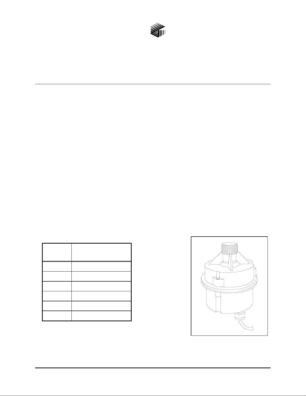
Model 13314-003 Div. 2 Hazardous Area
70-Volt Horn Driver
Confidentiality Notice
This manual is provided solely as an operational, installation, and maintenance guide and contains
sensitive business and technical information that is confidential and proprietary to GAI-Tronics. GAITronics retains all intellectual property and other rights in or to the information contained herein, and
such information may only be used in connection with the operation of your GAI-Tronics product or
system. This manual may not be disclosed in any form, in whole or in part, directly or indirectly, to any
third party.
Introduction
The GAI-Tronics Model 13314-003 Div. 2 Hazardous Area 70-Volt Horn Driver is constructed of black
glass and fiber-reinforced polyester thermoplastic and has a rain-tight construction. It is built to
withstand harsh industrial environments and is approved for installation in hazardous areas.
Mounting Instructions
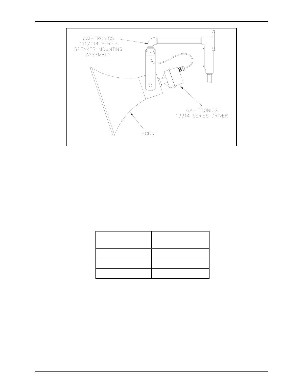
A typical installation of a 13314 Series Driver with associated horn and mounting assembly is shown in
Figure 3. The recommended mounting height for the driver is 9 feet (2.7 meters) from the floor. Refer to
the following chart to verify that the horn is paired with the correct speaker mounting assembly.
Horn
Series
13302 411A
13304 411A
13305 411A
13306 414-002
13309 411A
13340 411A
Speaker Mounting
Assembly
Figure 1. Model 13314-003 Div. 2
Hazardous Area 70-Volt Horn
Driver
GAI-Tronics Corporation 400 E. Wyomissing Ave. Mohnton, PA 19540 USA
610-777-1374 800-492-1212 Fax: 610-796-5954
ISIT WWW.GAI-TRONICS.COM FOR PRODUCT LITERATURE AND MANUALS
V
Page 2
Pub. 42004-096D
Model 13314-003 Div. 2 Hazardous Area 70 Volt Horn Driver Page:
Figure 2. Typical Installation
2 of 4
The installation of this speaker assembly must conform to regulations governing electrical equipment for
hazardous locations and provisions of the National Electrical Code.
Install the mounting assembly and the horn, then complete the following instructions to install the driver
onto the horn.
Wiring Instructions
Refer to the following chart to determine the appropriate gauge speaker cable.
Cable
Options
No. 18 AWG 6,250
No. 16 AWG 9,900
No. 14 AWG 15,800
Field wiring to the driver must be made using the attached three-conductor type SO cord. Connect these
wires as follows:
Distance of Cable
Run in Feet
• Green: earth ground
• Black: amplifier 70V + terminal
• White: amplifier 70V − (com) terminal
The horn driver is factory-connected for 30-watt tap setting. If no wattage tap changes are required,
screw the driver assembly onto the rear of the horn as shown in Figure 2.
f:\standard ioms - current release\42004 instr. manuals\42004-096d.doc
05/11
Page 3

Pub. 42004-096D
Model 13314-003 Div. 2 Hazardous Area 70 Volt Horn Driver Page:
3 of 4
Changing the Wattage Tap Setting
1. If another wattage tap setting is desired, it is recommended that the driver assembly be disconnected
and removed from the horn for convenience of changing taps.
2. Remove the three Phillips screws that hold the driver together, and pull the rear assembly away from
the front assembly. See Figure 3. Use care to avoid damaging the gasket.
Figure 3. Driver Outline Diagram
3. Unscrew the wire nut from the driver transformer’s brown wire that is joined to the driver cable’s
(SO cable) black wire. Terminate the brown wire with a nut or approved connector to avoid shorting
out.
4. Select the desired wattage tap wire, as shown in Figure 3.
5. Strip the wire back approximately 3/8 inch. Connect the desired wattage tap wire to the driver
cable’s black wire using a wire nut or approved connector.
6. It is not recommended that these wires be cut in case of future changes. Carefully push all primary
transformer wires into the space in the rear section of the enclosure.
7. After ensuring that the gasket is properly seated on the front assembly, align the rear assembly holes
with the front assembly holes and re-install the three screws.
8. Re-install the driver assembly to the horn and reconnect the cable to the field connection.
f:\standard ioms - current release\42004 instr. manuals\42004-096d.doc
05/11
Page 4

Pub. 42004-096D
Model 13314-003 Div. 2 Hazardous Area 70 Volt Horn Driver Page:
Driver Specifica tions
4 of 4
Power handling ...................... 30 W
300–3000 Hz; pink noise 6 dB crest factor; ref. ANSI S4.26–1984
RMS
Frequency response..................................................................................... 300–4500 Hz (depends on horn)
Input taps for 70 V line.................................................. 3.7, 7.5, 15, and 30 watts (factory set for 30 watts)
Sensitivity ........................................... 109 dB spl @ 1 watt, 1 meter; swept sine average with 13304 Horn
Horn coupling ........................................................................................... Standard 1.375–18 UNEF threads
Housing................................................................ Black; glass and fiber reinforced polyester thermoplastic
Bushing .......................................................................................... Nylon body with neoprene sealing gland
Cable ......................................Extra hard usage flexible cord (Type SO, 18/3) 42 inches (1066.8 mm) long
Impedance...................................................................................................................Variable (transformer)
Shipping weight .................................................................................................................... 4.3 lbs. (1.9 kg)
Dimensions ....................................................5.0 inches (127 mm) in diameter × 5.5 inches (140 mm) long
Approvals...................UL & cUL Listed for Class I, Div. 2 Groups A, B, C, D – Temp Code T2C at +40C
Class I, Div. 2 Groups A, B, C, D – Temp Code T2B at +55C
Class II, Div. 2 Groups F & G – Temp Code T4 at +55C
Class III, Div. 2
Weatherproof rating..........................................................................................................................Type 4X
f:\standard ioms - current release\42004 instr. manuals\42004-096d.doc
05/11
Page 5

Warranty
Equipment. GAI-Tronics warrants for a period of one (1) year from the date of shipment, that any
GAI-Tronics equipment supplied hereunder shall be free of defects in material and workmanship, shall
comply with the then-current product specifications and product literature, and if applicable, shall be fit
for the purpose specified in the agreed-upon quotation or proposal document. If (a) Seller’s goods prove
to be defective in workmanship and/or material under normal and proper usage, or unfit for the purpose
specified and agreed upon, and (b) Buyer’s claim is made within the warranty period set forth above,
Buyer may return such goods to GAI-Tronics’ nearest depot repair facility, freight prepaid, at which time
they will be repaired or replaced, at Seller’s option, without charge to Buyer. Repair or replacement shall
be Buyer’s sole and exclusive remedy. The warranty period on any repaired or replacement equipment
shall be the greater of the ninety (90) day repair warranty or one (1) year from the date the original
equipment was shipped. In no event shall GAI-Tronics warranty obligations with respect to equipment
exceed 100% of the total cost of the equipment supplied hereunder. Buyer may also be entitled to the
manufacturer’s warranty on any third-party goods supplied by GAI-Tronics hereunder. The applicability
of any such third-party warranty will be determined by GAI-Tronics.
Services. Any services GAI-Tronics provides hereunder, whether directly or through subcontractors,
shall be performed in accordance with the standard of care with which such services are normally
provided in the industry. If the services fail to meet the applicable industry standard, GAI-Tronics will
re-perform such services at no cost to buyer to correct said deficiency to Company's satisfaction provided
any and all issues are identified prior to the demobilization of the Contractor’s personnel from the work
site. Re-performance of services shall be Buyer’s sole and exclusive remedy, and in no event shall GAITronics warranty obligations with respect to services exceed 100% of the total cost of the services
provided hereunder.
Warranty Periods. Every claim by Buyer alleging a defect in the goods and/or services provided
hereunder shall be deemed waived unless such claim is made in writing within the applicable warranty
periods as set forth above. Provided, however, that if the defect complained of is latent and not
discoverable within the above warranty periods, every claim arising on account of such latent defect shall
be deemed waived unless it is made in writing within a reasonable time after such latent defect is or
should have been discovered by Buyer.
Limitations / Exclusions. The warranties herein shall not apply to, and GAI-Tronics shall not be
responsible for, any damage to the goods or failure of the services supplied hereunder, to the extent
caused by Buyer’s neglect, failure to follow operational and maintenance procedures provided with the
equipment, or the use of technicians not specifically authorized by GAI-Tronics to maintain or service the
equipment. THE WARRANTIES AND REMEDIES CONTAINED HEREIN ARE IN LIEU OF AND
EXCLUDE ALL OTHER WARRANTIES AND REMEDIES, WHETHER EXPRESS OR IMPLIED BY
OPERATION OF LAW OR OTHERWISE, INCLUDING ANY WARRANTIES OF
MERCHANTABILITY OR FITNESS FOR A PARTICULAR PURPOSE.
Return Policy
If the equipment requires service, contact your Regional Service Center for a return authorization number
(RA#). Equipment should be shipped prepaid to GAI-Tronics with a return authorization number and a
purchase order number. If the equipment is under warranty, repairs or a replacement will be made in
accordance with the warranty policy set forth above. Please include a written explanation of all defects to
assist our technicians in their troubleshooting efforts.
Call 800-492-1212 (inside the USA) or 610-777-1374 (outside the USA) for help identifying the
Regional Service Center closest to you.
(Rev. 10/06)
 Loading...