

Page 1
Pub. 42004-353E
GAI-TRONICS® CORPORATION
A HUBBELL COMPANY
13310 Series
Explosion-proof Drivers
Confidentiality Notice
This manual is provided solely as an installation, operation and maintenance guide and contains sensitive
business and technical information that is confidential and proprietary to GAI-Tronics. GAI-Tronics
retains all intellectual property and other rights in or to the information contained herein, and such
information may only be used in connection with the operation of your GAI-Tronics product or system.
This manual may not be disclosed in any form, in whole or in part, directly or indirectly, to any third party.
Mounting Instructions
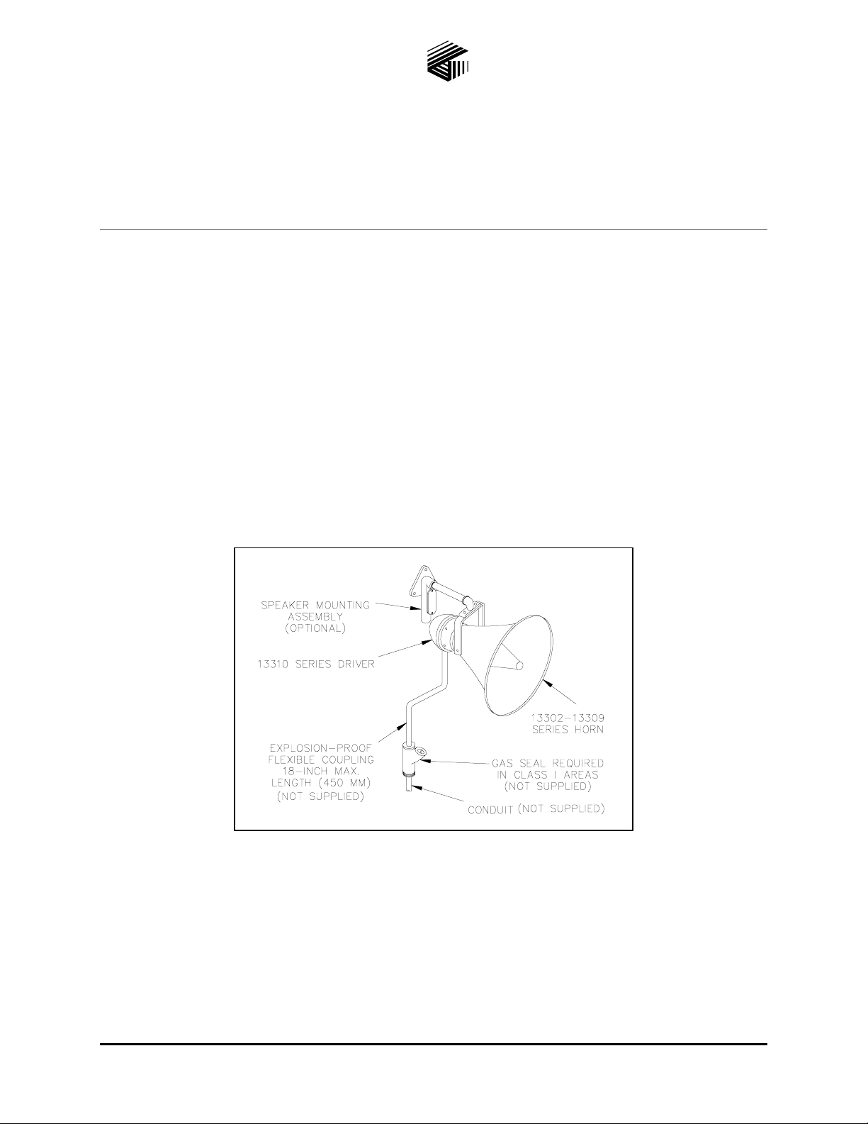
See Figure 1 for the 13310 Series Driver installation configuration with an associated horn and mounting
assembly. The installation of explosion-proof speakers must conform with regulations governing
electrical equipment for hazardous locations and the provisions of the National Electrical Code.
NO ALTERATIONS MAY BE MADE TO THESE DRIVER UNITS!
Figure 1. 13310 Series Driver Installation
No holes may be made or holding devices screwed into the case, which may weaken or endanger the
structure after installation. All main bolts on the case housing of the driver must be tightened to
10.8–12.5 ft-lbs. dry (14.6–17 n-m dry).
Wiring may be run in threaded rigid or approved standard electrical flexible conduit with five full threads
engaged. Explosion-proof conduit boxes, junctions, and fittings are of approved type and usually contain
screw-in covers. Unions, elbows, and bends are also of special design.
GAI-Tronics Corporation 400 E. Wyomissing Ave. Mohnton, PA 19540 USA
610-777-1374 800-492-1212 Fax: 610-796-5954
ISIT WWW.GAI-TRONICS.COM FOR PRODUCT LITERATURE AND MANUALS
V
Page 2
Pub. 42004-353E
GAI-Tronics 13310 Series Explosion-proof Drivers Page:
2 of 2
Electrical Connection
The Model 13310-201 Driver has a 16-ohm impedance, and if used singly, connects to the 16-ohm
amplifier output tap. If two drivers are used, connect in parallel to the 8-ohm amplifier output tap.
The Model 13310-202 Driver has an 8-ohm impedance and if used singly, connects to the 8-ohm
amplifier output. If two drivers are used, connect in series to the 16-ohm output.
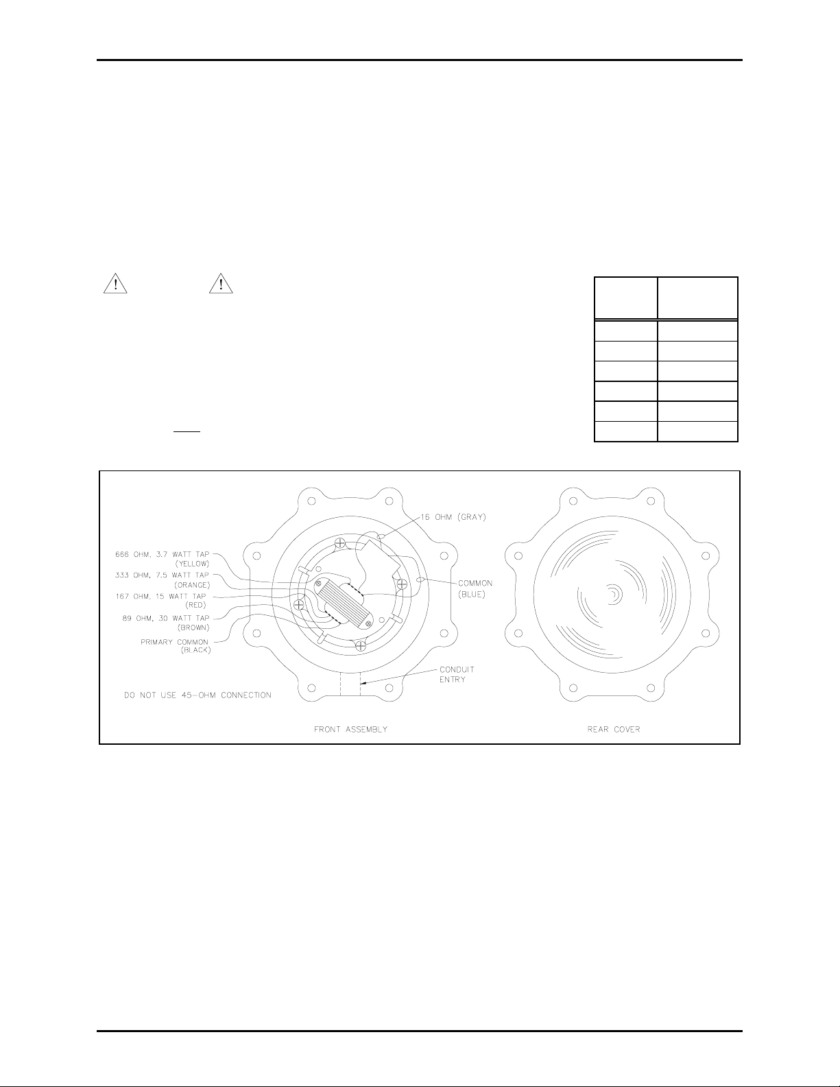
The Model 13310-203 Driver has a 70.7 V transformer. Connect the transformer for the power level
desired (30 watts max.). See Figure 2.
CAUTION
Installation must be in accordance with National
Electrical Code for the appropriate hazardous area classification.
1. Select the speaker mounting assembly based on the horn being used.
Refer to the chart at the right. The suggested mounting height is
9 feet (2.7 meters) above the floor.
2. In hazardous areas, use the speaker mounting assembly to support the
speaker only
. Do not route electrical connections through the mounting
assembly.
Horn
Series
Mounting
Assembly
13302 415A
13304 415A
13305 413A
13306 415A
13309 415A
13340 415A
Figure 2. Front and Rear Halves of Model 13310-203 Driver Assembly – Output Tap Locations
Specifications
Power capacity.....................................................................................................30 watts continuous power
Impedance.................................................................................................16 ohms (voice coil) – 13310-201
8-ohms – 13310-202
70 V – 13310-203
Conduit attachment....................................................................... Standard 1/2 inch (1.27 cm) pipe conduit
Horn coupling............................................................................... Standard 1-3/8 inch (3.5 cm) - 18 threads
Approval ..................... UL listed [E71922] for Class I, Groups B, C and D, Hazardous Gas Areas (Div. 1)
f:\standard ioms - current release\42004 instr. manuals\42004-353e.doc
03/11
Page 3

Warranty
Equipment. GAI-Tronics warrants for a period of one (1) year from the date of shipment, that any
GAI-Tronics equipment supplied hereunder shall be free of defects in material and workmanship, shall
comply with the then-current product specifications and product literature, and if applicable, shall be fit
for the purpose specified in the agreed-upon quotation or proposal document. If (a) Seller’s goods prove
to be defective in workmanship and/or material under normal and proper usage, or unfit for the purpose
specified and agreed upon, and (b) Buyer’s claim is made within the warranty period set forth above,
Buyer may return such goods to GAI-Tronics’ nearest depot repair facility, freight prepaid, at which time
they will be repaired or replaced, at Seller’s option, without charge to Buyer. Repair or replacement shall
be Buyer’s sole and exclusive remedy. The warranty period on any repaired or replacement equipment
shall be the greater of the ninety (90) day repair warranty or one (1) year from the date the original
equipment was shipped. In no event shall GAI-Tronics warranty obligations with respect to equipment
exceed 100% of the total cost of the equipment supplied hereunder. Buyer may also be entitled to the
manufacturer’s warranty on any third-party goods supplied by GAI-Tronics hereunder. The applicability
of any such third-party warranty will be determined by GAI-Tronics.
Services. Any services GAI-Tronics provides hereunder, whether directly or through subcontractors,
shall be performed in accordance with the standard of care with which such services are normally
provided in the industry. If the services fail to meet the applicable industry standard, GAI-Tronics will
re-perform such services at no cost to buyer to correct said deficiency to Company's satisfaction provided
any and all issues are identified prior to the demobilization of the Contractor’s personnel from the work
site. Re-performance of services shall be Buyer’s sole and exclusive remedy, and in no event shall GAITronics warranty obligations with respect to services exceed 100% of the total cost of the services
provided hereunder.
Warranty Periods. Every claim by Buyer alleging a defect in the goods and/or services provided
hereunder shall be deemed waived unless such claim is made in writing within the applicable warranty
periods as set forth above. Provided, however, that if the defect complained of is latent and not
discoverable within the above warranty periods, every claim arising on account of such latent defect shall
be deemed waived unless it is made in writing within a reasonable time after such latent defect is or
should have been discovered by Buyer.
Limitations / Exclusions. The warranties herein shall not apply to, and GAI-Tronics shall not be
responsible for, any damage to the goods or failure of the services supplied hereunder, to the extent
caused by Buyer’s neglect, failure to follow operational and maintenance procedures provided with the
equipment, or the use of technicians not specifically authorized by GAI-Tronics to maintain or service the
equipment. THE WARRANTIES AND REMEDIES CONTAINED HEREIN ARE IN LIEU OF AND
EXCLUDE ALL OTHER WARRANTIES AND REMEDIES, WHETHER EXPRESS OR IMPLIED BY
OPERATION OF LAW OR OTHERWISE, INCLUDING ANY WARRANTIES OF
MERCHANTABILITY OR FITNESS FOR A PARTICULAR PURPOSE.
Return Policy
If the equipment requires service, contact your Regional Service Center for a return authorization number
(RA#). Equipment should be shipped prepaid to GAI-Tronics with a return authorization number and a
purchase order number. If the equipment is under warranty, repairs or a replacement will be made in
accordance with the warranty policy set forth above. Please include a written explanation of all defects to
assist our technicians in their troubleshooting efforts.
Call 800-492-1212 (inside the USA) or 610-777-1374 (outside the USA) for help identifying the
Regional Service Center closest to you.
(Rev. 10/06)
 Loading...