

Page 1

Pub. 42003-271A
GAI-TRONICS® CORPORATION
A HUBBELL COMPANY
Zone 2/22 ICS 70V/100V Upgrade Kit
Model 12832-002
Confidential ity Notice
This manual is provided solely as an operational, installation, and maintenance guide and contains
sensitive business and technical information that is confidential and proprietary to GAI-Tronics.
GAI-Tronics retains all intellectual property and other rights in or to the information contained herein,
and such information may only be used in connection with the operation of your GAI-Tronics product or
system. This manual may not be disclosed in any form, in whole or in part, directly or indirectly, to any
third party.
General Information
The Model 12832-002 Zone 2/22 ICS 70V/100V Upgrade Kit is designed to be used in Zone 2/22 ICS
Stations. This kit provides all components required to upgrade the station to connect 70-volt or 100-volt
speakers and daisy-chain multiple speakers to a single ICS Page/Party
This kit provides the following components:
Qty Description
1 Toroid transformer assembly with terminal block and bracket
4 Nut, 4-40 keps
4
1 Tie wrap
1 Label, Upgrade Kit
Standoff, ¼-inch hex 4-40
1 3/16-inches
®
station.
Installation
WARNING
removed or the area is known to be non-hazardous.
Opening the Station
EXPLOSION HAZARD – Do not disconnect equipment unless power has been
Remove the four screws from the front panel and turn it to the right so that the interior surface faces you.
Allow the wiring and ribbon cables to remain connected. The front panel can be hung from the front door
by hooking a small piece of wire in the mounting holes of the panel. The front panel interior surface and
the back box interior now face you. This configuration presents the easiest access for troubleshooting and
setting adjustments. See Figure 1.
GAI-Tronics Corporation 400 E. Wyomissing Ave. Mohnton, PA 19540 USA
610-777-1374 800-492-1212 Fax: 610-796-5954
V
ISIT WWW.GAI-TRONICS.COM FOR PRODUCT LITERATURE AND MANUALS
Page 2

Pub. 42003-271A
ODEL 12832-002 ZONE 2/22 ICS 70 V/100V UPGRADE KIT Page 2 of 5
M
Figure 1. ICS Zone 2/22 Station – Interior View
Installing the 70V/100V Option
1. Cut the tie wrap that is securing the ground wire and RTU cable assembly (when applicable).
2. Remove standoff and tie anchor mount by removing the screw.
3. On the Termination PCBA, unplug the ribbon cable at P3 for easier access to the rear mounting plate.
4. When applicable, remove the four 4-40 screws that secure the RTU PCBA, the RTU PCBA and the
four 4-40 7/16-inch female/female standoffs from the rear mounting panel. Set these aside.
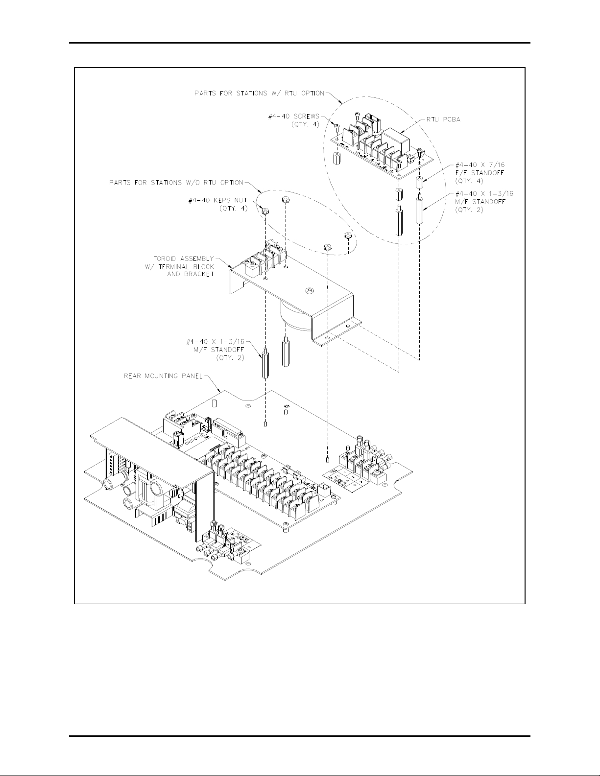
5. Attach two of the 4-40 1-3/16-inch male/female standoffs to the rear mounting panel. Attach the
bracket and toroid assembly to the rear mounting panel using the four 4-40 keps nuts if there is no
RTU option. See Figure 2.
6. If there is an RTU option, attach the bracket with two more 4-40 1-3/16-inch male/female standoffs.
Use the four 4-40 7/16-inch female/female standoffs to secure the bracket. Re-attach the RTU
PCBA to the standoffs and bracket using the 4-40 screws. See Figure 2.
f:\standard ioms - current release\42003 kit manuals \42003-271a. doc
03/14
Page 3
Pub. 42003-271A
ODEL 12832-002 ZONE 2/22 ICS 70 V/100V UPGRADE KIT Page 3 of 5
M
Figure 2. 70V/ 100V Assembly
f:\standard ioms - current release\42003 kit manuals \42003-271a. doc
03/14
Page 4

Pub. 42003-271A
ODEL 12832-002 ZONE 2/22 ICS 70 V/100V UPGRADE KIT Page 4 of 5
M
7. Plug the ribbon cable back into P3 of the Termination PCBA.
8. Tie down the ground cable and RTU cable (when applicable) to the tie anchor mount on the terminal
block.
9. Place the Upgrade Kit label on the power supply housing as shown in Figure 3.
Figure 3. Upgraded ICS Zone 2/22 Station – Interior View
Field Wiring
For 100V speakers, connect the wires to the terminal block TB8-100V and COM. For the 70V speakers,
connect the wires to the terminal block TB8-70V and COM.
Figure 4. Standard Station 70V/100V Speaker Output Assembly
f:\standard ioms - current release\42003 kit manuals \42003-271a. doc
03/14
Page 5

Pub. 42003-271A
ODEL 12832-002 ZONE 2/22 ICS 70 V/100V UPGRADE KIT Page 5 of 5
M
Figure 5. 70V/100V Speaker Connections
Attaching the Front Panel
After all adjustments have been completed, place the front cover in the rear enclo sure, bei ng careful not to
pinch any cables. Secure the front cover using the four screws and washers provided. Torque the screws
to 50 in-lbs (5.65 n-m).
f:\standard ioms - current release\42003 kit manuals \42003-271a. doc
03/14
Page 6

Warranty
Equipment. GAI-Tronics warrants for a period of one (1) year from the date of shipment, that any
GAI-Tronics equipment supplied hereunder shall be free of defects in material and workmanship, shall
comply with the then-current product specifications and product literature, and if applicable, shall be fit
for the purpose specified in the agreed-upon quotation or proposal document. If (a) Seller’s goods prove
to be defective in workmanship and/or material under normal and proper usage, or unfit for the purpose
specified and agreed upon, and (b) Buyer’s claim is made within the warranty period set forth above,
Buyer may return such goods to GAI-Tronics’ nearest depot repair facility, freight prepaid, at which time
they will be repaired or replaced, at Seller’s option, without charge to Buyer. Repair or replacement shall
be Buyer’s sole and exclusive remedy. The warranty period on any repaired or replacement equipment
shall be the greater of the ninety (90) day repair warranty or one (1) year from the date the original
equipment was shipped. In no event shall GAI-Tronics warranty obligations with respect to equipment
exceed 100% of the total cost of the equipment supplied hereunder. Buyer may also be entitled to the
manufacturer’s warranty on any third-party goods supplied by GAI-Tronics hereunder. The applicability
of any such third-party warranty will be determined by GAI-Tronics.
Services. Any services GAI-Tronics provides hereunder, whether directly or through subcontractors,
shall be performed in accordance with the standard of care with which such services are normally
provided in the industry. If the services fail to meet the applicable industry standard, GAI-Tronics will
re-perform such services at no cost to buyer to correct said deficiency to Company's satisfaction provided
any and all issues are identified prior to the demobilization of the Contractor’s personnel from the work
site. Re-performance of services shall be Buyer’s sole and exclusive remedy, and in no event shall GAITronics warranty obligations with respect to services exceed 100% of the total cost of the services
provided hereunder.
Warranty Periods. Every claim by Buyer alleging a defect in the goods and/or services provided
hereunder shall be deemed waived unless such claim is made in writing within the applicable warranty
periods as set forth above. Provided, however, that if the defect complained of is latent and not
discoverable within the above warranty periods, every claim arising on account of such latent defect shall
be deemed waived unless it is made in writing within a reasonable time after such latent defect is or
should have been discovered by Buyer.
Limitations / Exclusions. The warranties herein shall not apply to, and GAI-Tronics shall not be
responsible for, any damage to the goods or failure of the services supplied hereunder, to the extent
caused by Buyer’s neglect, failure to follow operational and maintenance procedures provided with the
equipment, or the use of technicians not specifically authorized by GAI-Tronics to maintain or service the
equipment. THE WARRANTIES AND REMEDIES CONTAINED HEREIN ARE IN LIEU OF AND
EXCLUDE ALL OTHER WARRANTIES AND REMEDIES, WHETHER EXPRESS OR IMPLIED BY
OPERATION OF LAW OR OTHERWISE, INCLUDING ANY WARRANTIES OF
MERCHANTABILITY OR FITNESS FOR A PARTICULAR PURPOSE.
Return Policy
If the equipment requires service, contact your Regional Service Center for a return authorization number
(RA#). Equipment should be shipped prepaid to GAI-Tronics with a return authorization number and a
purchase order number. If the equipment is under warranty, repairs or a replacement will be made in
accordance with the warranty policy set forth above. Please include a written explanation of all defects to
assist our technicians in their troubleshooting efforts.
Call 800-492-1212 (inside the USA) or 610-777-1374 (outside the USA) for help identifying the
Regional Service Center closest to you.
(Rev. 10/06)
 Loading...