

Page 1

Pub. 42003-268A
GAI-TRONICS® CORPORATION
A HUBBELL COMPANY
Hazardous Area ICS Termination PCBA
Upgrade Kits
Models 12831-007 and 12831-008
Confidentiality Notice
This manual is provided solely as an operational, installation, and maintenance guide and contains
sensitive business and technical information that is confidential and proprietary to GAI-Tronics.
GAI-Tronics retains all intellectual property and other rights in or to the information contained herein,
and such information may only be used in connection with the operation of your GAI-Tronics product or
system. This manual may not be disclosed in any form, in whole or in part, directly or indirectly, to any
third party.
General Information
The Model 12831-007 and 12831-008 Hazardous Area ICS Termination PCBA Kits are designed to be
used in Hazardous Area ICS stations equipped with first-generation termination PCBAs (Part No. 69554xxx.) Each kit provides all components required to upgrade the termination PCBA to the latest version
(Part No. 69630-xxx.)
These kits include the following components:
Qty Description
1 ICS Termination PCBA
6
1 Input power cable assembly
1 24 V dc power input label (Model 12831-008 only)
1 Upgrade kit label
Screw, 4-40 ¼-inch PHMS
Installation
WARNING
power from the station.
Before performing any of the following settings and adjustments, remove all
WARNING
supply circuit before making any adjustments to the amplifier’s handset level.
GAI-Tronics Corporation 400 E. Wyomissing Ave. Mohnton, PA 19540 USA
To reduce the risk of hazardous atmospheres, disconnect the equipment from the
610-777-1374 800-492-1212 Fax: 610-796-5954
V
ISIT WWW.GAI-TRONICS.COM FOR PRODUCT LITERATURE AND MANUALS
Page 2
Pub. 42003-268A
ODEL 12831-007 & 12831-008 HAZARDOUS AREA ICS TERMINATION PCBA UPGRADE KITS Page 2 of 6
M
Opening the Station
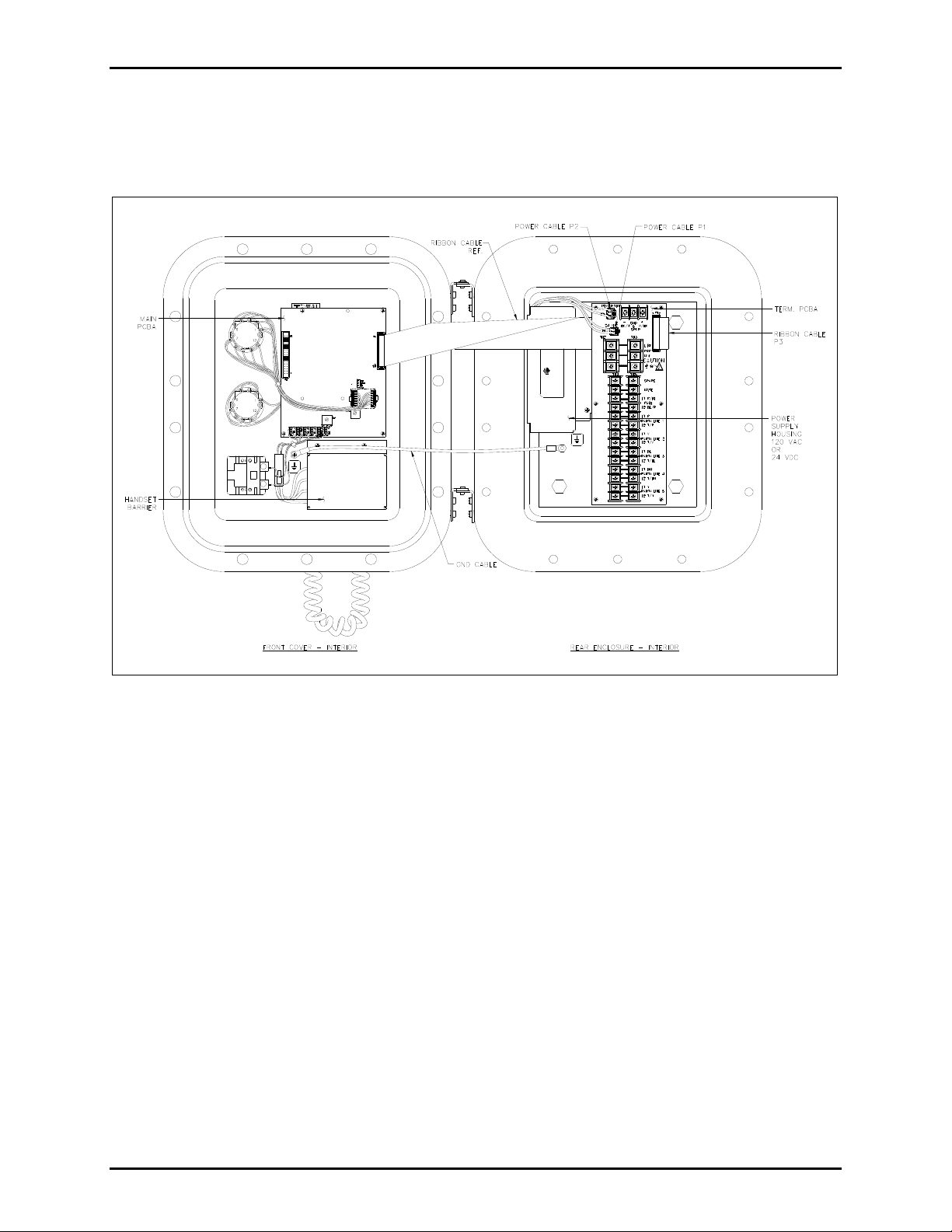
Remove all cover bolts from the enclosure. Swing the front door open to access the internal PCBAs. See
Figure 1.
Figure 1. ICS Hazardous Area Station – Interior View
Installing the Termination PCBA
1. On the Termination PCBA, unplug the ribbon cable at P3, and the power cables at P1 and P2.
2. Remove the six screws that secure the Termination PCBA to the rear mounting plate and remove the
Termination PCBA. Keep the ribbon cable routed under the insulator.
3. Remove the two screws that secure the power supply housing to the rear mounting plate.
4. Unplug the input power cable assembly from the ac or dc power supply. The ac power connector is a
three-position plug and the dc power connector is a five-position plug.
5. Plug in the new input power cable assembly provided with the kit into the power supply.
6. Reattach power supply housing to the rear mounting plate with two screws, routing the wires behind
the power supply and housing.
7. Attach the new Termination PCBA to the rear mounting plate with six screws.
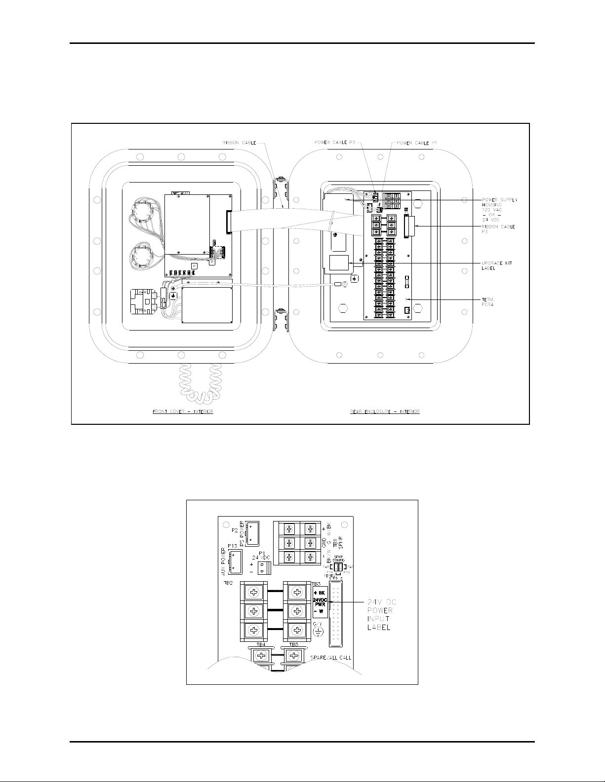
8. Place the upgrade kit label on the power supply housing as shown in Figure 2.
f:\standard ioms - current release\42003 kit manuals\42003-268a.docx
02/14
Page 3
Pub. 42003-268A
ODEL 12831-007 & 12831-008 HAZARDOUS AREA ICS TERMINATION PCBA UPGRADE KITS Page 3 of 6
M
9. Plug the ribbon cable back into P3 of the Termination PCBA.
10. Plug the power cables back into P1 and P2 of the Termination PCBA. Refer to Figure 2 for the
completed assembly configuration.
Figure 2. Upgraded ICS Hazardous Area Station – Interior View
11. For dc kits, attach the 24 V dc power input label to the Termination PCBA at the location shown in
Figure 3.
Figure 3. Location for placement of 24 V dc power input label on the Termination PCBA
f:\standard ioms - current release\42003 kit manuals\42003-268a.docx
02/14
Page 4

Pub. 42003-268A
ODEL 12831-007 & 12831-008 HAZARDOUS AREA ICS TERMINATION PCBA UPGRADE KITS Page 4 of 6
M
Field Wiring
The ICS Page/Party® station provides terminal blocks for field wiring. Each connection for the system
cable has two terminals for daisy-chain wiring. Attach #6 spade lugs to the wires before attachment to the
terminal blocks for the most secure connection.
The terminal blocks on the Termination PCBA are labeled to coincide with the color code used on GAITronics 60029 series multi-party cable or 60038 series single party cable. Refer to Figure 4 for a sample
wiring diagram.
Figure 4. Typical Page/Party
®
ICS Station Wiring Diagram
In certain circumstances where paging audio induces feedback, muting the speakers of two or more
stations during a page, referred to as mutual muting, can eliminate such feedback problems. This function
is enabled by connecting the spare orange wire between stations to terminal block TB4-2 or TB5-2.
f:\standard ioms - current release\42003 kit manuals\42003-268a.docx
02/14
Page 5

Pub. 42003-268A
ODEL 12831-007 & 12831-008 HAZARDOUS AREA ICS TERMINATION PCBA UPGRADE KITS Page 5 of 6
M
Speaker Jumper Impedance Configuration
Configure speaker jumpers P15 and P16 for the appropriate impedance for either 8-ohm or 16-ohm
speakers as shown in Figure 5 below.
Figure 5. Speaker Jumper Impedance Configuration Options for 8-ohm or 16-ohm Speakers
f:\standard ioms - current release\42003 kit manuals\42003-268a.docx
02/14
Page 6

Pub. 42003-268A
ODEL 12831-007 & 12831-008 HAZARDOUS AREA ICS TERMINATION PCBA UPGRADE KITS Page 6 of 6
M
Attaching the Front Cover
1. After all connections have been completed, inspect and clean the machined flange joint surface of
both the cover and the box. Surfaces must be smooth, free of nicks, scratches, dirt or any foreign
particle build-up that would prevent a proper seal. Surfaces must seat fully against each other to
provide a proper explosion-proof joint. Clean surfaces by wiping with a clean lint-free cloth.
2. Apply a light coat of Killark “LUBG” lubricant to flange surfaces and close the cover. Install and
tighten all cover bolts to 30 ft-lbs. Make certain no cover bolts are omitted. Use only those bolts
supplied with the enclosure.
3. Reapply power to the station.
Refer to Pub. 42004-723L2 for general information.
f:\standard ioms - current release\42003 kit manuals\42003-268a.docx
02/14
Page 7

Warranty
Equipment. GAI-Tronics warrants for a period of one (1) year from the date of shipment, that any
GAI-Tronics equipment supplied hereunder shall be free of defects in material and workmanship, shall
comply with the then-current product specifications and product literature, and if applicable, shall be fit
for the purpose specified in the agreed upon quotation or proposal document. If (a) Seller’s goods prove
to be defective in workmanship and/or material under normal and proper usage, or unfit for the purpose
specified and agreed upon, and (b) Buyer’s claim is made within the warranty period set forth above,
Buyer may return such goods to GAI-Tronics nearest depot repair facility, freight prepaid, at which time
they will be repaired or replaced, at Seller’s option, without charge to Buyer. Repair or replacement shall
be Buyer’s sole and exclusive remedy. The warranty period on any repaired or replacement equipment
shall be the greater of the ninety (90) day repair warranty or one (1) year from the date the original
equipment was shipped. In no event shall GAI-Tronics warranty obligations with respect to equipment
exceed 100% of the total cost of the equipment supplied hereunder. Buyer may also be entitled to the
manufacturer’s warranty on any third-party goods supplied by GAI-Tronics hereunder. The applicability
of any such third-party warranty will be determined by GAI-Tronics.
Services. Any services GAI-Tronics provides hereunder, whether directly or through subcontractors,
shall be performed in accordance with the standard of care with which such services are normally
provided in the industry. If the services fail to meet the applicable industry standard, GAI-Tronics will reperform such services at no cost to buyer to correct said deficiency to Company's satisfaction provided
any and all issues are identified prior to the demobilization of the Contractor's personnel from the work
site. Re-performance of services shall be Buyer's sole and exclusive remedy, and in no event shall GAITronics warranty obligations with respect to services exceed 100% of the total cost of the services
provided hereunder.
Warranty Periods. Every claim by Buyer alleging a defect in the goods and/or services provided
hereunder shall be deemed waived unless such claim is made in writing within the applicable warranty
periods as set forth above. Provided, however, that if the defect complained of is latent and not
discoverable within the above warranty periods, every claim arising on account of such latent defect shall
be deemed waived unless it is made in writing within a reasonable time after such latent defect is or
should have been discovered by Buyer.
Limitations / Exclusions. The warranties herein shall not apply to, and GAI-Tronics shall not be
responsible for, any damage to the goods or failure of the services supplied hereunder, to the extent
caused by Buyer’s neglect, failure to follow operational and maintenance procedures provided with the
equipment, or the use of technicians not specifically authorized by GAI-Tronics to maintain or service the
equipment. THE WARRANTIES AND REMEDIES CONTAINED HEREIN ARE IN LIEU OF AND
EXCLUDE ALL OTHER WARRANTIES AND REMEDIES, WHETHER EXPRESS OR IMPLIED BY
OPERATION OF LAW OR OTHERWISE, INCLUDING ANY WARRANTIES OF
MERCHANTABILITY OR FITNESS FOR A PARTICULAR PURPOSE.
Return Policy
If the equipment requires service, contact your Regional Service Center for a return authorization number
(RA#). Equipment should be shipped prepaid to GAI-Tronics with a return authorization number and a
purchase order number. If the equipment is under warranty, repairs or a replacement will be made in
accordance with the warranty policy set forth above. Please include a written explanation of all defects to
assist our technicians in their troubleshooting efforts.
Call 800-492-1212 (inside the USA) or 610-777-1374 (outside the USA) for help identifying the
Regional Service Center closest to you.
(Rev. 10/06)
 Loading...