

Page 1

Pub. 42003- 252A
GAI-TRONICS® CORPORATION
A HUBBELL COMPANY
IS Barrier Replacement Kit
for Ex d ib ICS Stations
Model 12823-001
Confidential ity Notice
This manual is provided solely as an operational, installation, and maintenance guide and contains
sensitive business and technical information that is confidential and proprietary to GAI-Tronics.
GAI-Tronics retains all intellectual property and other rights in or to the information contained herein,
and such information may only be used in connection with the operation of your GAI-Tronics product or
system. This manual may not be disclosed in any form, in whole or in part, directly or indirectly, to any
third party.
General Information
The Model 12823-001 IS (Intrinsically Safe) Barrier Replacement Kit is intended for use in replacing the
handset IS Barrier assembly on GAI-Tronics Ex d ib ICS Stations. This kit consists of the following
components:
Qty Description
1 Handset Safety Barrier PCBA Assembly
2
Screw, 6-32 5/16-inch PHMS
Installation
WARNING
Important Safety Instructions
1. Read, follow and retain instructions. – All safety and operating instructions should be read and
followed before opening the unit. Retain the instructions for future reference.
2. Heed warnings – Adhere to all warnings on the unit and in the operating instructions.
Disconnect the equipment from the supply circuit before opening.
3. Servicing – Do not attempt to service this unit by yourself. Opening or removing covers may expose
you to dangerous voltage or other hazards. Refer all servicing to qualified service personnel.
WARNING
the station.
GAI-Tronics Corporation 400 E. Wyomissing Ave. Mohnton, PA 19540 USA
Before performing any of the following adjustments, remove all power from
610-777-1374 800-492-1212 Fax: 610-796-5954
V
ISIT WWW.GAI-TRONICS.COM FOR PRODUCT LITERATURE AND MANUALS
Page 2
Pub. 42003-252A
ODEL 12823-001 IS BARRIER REPLACEMENT KIT FOR EX d ib ICS STATIONS Page: 2 of 3
M
Removing the Old Handset Safety IS Barrier Assembly PCBA
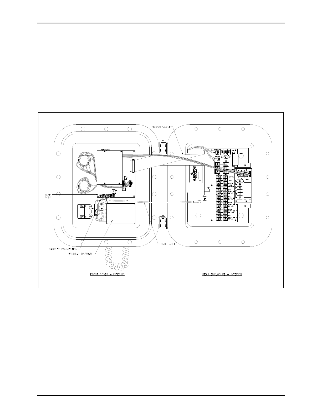
1. Remove all cover bolts from the enclosure. Swing the front door open to access the internal printed
circuit board assemblies (P CBAs).
2. Disconnect the connection between the Handset IS Barrier and the Main PCBA on the front cover.
Remove the two screws holding the handset barrier assembly to the front cover. Set the screws aside
for re-assembly. See Figure 1.
3. Disconnect the four handset wires from the IS Barrier assembly and make note of the connection
locations.
f:\standard ioms - current release\42003 kit manuals \42003-252a. doc
03/12
Figure 1.
Page 3

Pub. 42003-252A
ODEL 12823-001 IS BARRIER REPLACEMENT KIT FOR EX d ib ICS STATIONS Page: 3 of 3
M
Installing the New Handset Safety IS Barrier A ssembly PCBA
1. Connect the handset wires to the new IS Barrier assembly. See the connection detail in Figure 2
below.
Figure 2. Connection Detail
2. Place the new IS Barrier assembly into position on the front cover. Secure using the existing screws.
3. Plug the IS Barrier assembly into the mating connector attached to the Main PCBA.
4. Inspect and clean the machined flange joint surfaces of both the cover and the box. Surfaces must be
smooth, free of nicks, scratches, dirt or any foreign particle build-up that would prevent a proper seal.
Surfaces must seat fully against each other to provide a proper explosion-proof joint. Clean surfaces
by wiping with a clean, lint-free cloth.
5. Apply a light coat of Killark “LUBG” lubricant to flange surfaces and close the cover. Install and
tighten all cover bolts to 30 ft-lbs. Make certain no cover bolts are omitted. Use only those bolts
supplied with the enclosure.
6. Insure proper grounding to protective earth.
7. Reapply power to the station.
f:\standard ioms - current release\42003 kit manuals \42003-252a. doc
03/12
Page 4

Warranty
Equipment. GAI-Tronics warrants for a period of one (1) year from the date of shipment, that any
GAI-Tronics equipment supplied hereunder shall be free of defects in material and workmanship, shall
comply with the then-current product specifications and product literature, and if applicable, shall be fit
for the purpose specified in the agreed-upon quotation or proposal document. If (a) Seller’s goods prove
to be defective in workmanship and/or material under normal and proper usage, or unfit for the purpose
specified and agreed upon, and (b) Buyer’s claim is made within the warranty period set forth above,
Buyer may return such goods to GAI-Tronics’ nearest depot repair facility, freight prepaid, at which time
they will be repaired or replaced, at Seller’s option, without charge to Buyer. Repair or replacement shall
be Buyer’s sole and exclusive remedy. The warranty period on any repaired or replacement equipment
shall be the greater of the ninety (90) day repair warranty or one (1) year from the date the original
equipment was shipped. In no event shall GAI-Tronics warranty obligations with respect to equipment
exceed 100% of the total cost of the equipment supplied hereunder. Buyer may also be entitled to the
manufacturer’s warranty on any third-party goods supplied by GAI-Tronics hereunder. The applicability
of any such third-party warranty will be determined by GAI-Tronics.
Services. Any services GAI-Tronics provides hereunder, whether directly or through subcontractors,
shall be performed in accordance with the standard of care with which such services are normally
provided in the industry. If the services fail to meet the applicable industry standard, GAI-Tronics will
re-perform such services at no cost to buyer to correct said deficiency to Company's satisfaction provided
any and all issues are identified prior to the demobilization of the Contractor’s personnel from the work
site. Re-performance of services shall be Buyer’s sole and exclusive remedy, and in no event shall GAITronics warranty obligations with respect to services exceed 100% of the total cost of the services
provided hereunder.
Warranty Periods. Every claim by Buyer alleging a defect in the goods and/or services provided
hereunder shall be deemed waived unless such claim is made in writing within the applicable warranty
periods as set forth above. Provided, however, that if the defect complained of is latent and not
discoverable within the above warranty periods, every claim arising on account of such latent defect shall
be deemed waived unless it is made in writing within a reasonable time after such latent defect is or
should have been discovered by Buyer.
Limitations / Exclusions. The warranties herein shall not apply to, and GAI-Tronics shall not be
responsible for, any damage to the goods or failure of the services supplied hereunder, to the extent
caused by Buyer’s neglect, failure to follow operational and maintenance procedures provided with the
equipment, or the use of technicians not specifically authorized by GAI-Tronics to maintain or service the
equipment. THE WARRANTIES AND REMEDIES CONTAINED HEREIN ARE IN LIEU OF AND
EXCLUDE ALL OTHER WARRANTIES AND REMEDIES, WHETHER EXPRESS OR IMPLIED BY
OPERATION OF LAW OR OTHERWISE, INCLUDING ANY WARRANTIES OF
MERCHANTABILITY OR FITNESS FOR A PARTICULAR PURPOSE.
Return Policy
If the equipment requires service, contact your Regional Service Center for a return authorization number
(RA#). Equipment should be shipped prepaid to GAI-Tronics with a return authorization number and a
purchase order number. If the equipment is under warranty, repairs or a replacement will be made in
accordance with the warranty policy set forth above. Please include a written explanation of all defects to
assist our technicians in their troubleshooting efforts.
Call 800-492-1212 (inside the USA) or 610-777-1374 (outside the USA) for help identifying the
Regional Service Center closest to you.
(Rev. 10/06)
 Loading...