

Page 1

Pub. 42003-214B
GAI-TRONICS® CORPORATION
A HUBBELL COMPANY
RigCom PCBA Replacement Kits
Models 12803-001, 12803-002, 12803-003
Confidential ity Notice
This manual is provided solely as an operational, installation, and maintenance guide and contains
sensitive business and technical information that is confidential and proprietary to GAI-Tronics.
GAI-Tronics retains all intellectual property and other rights in or to the information contained herein,
and such information may only be used in connection with the operation of your GAI-Tronics product or
system. This manual may not be disclosed in any form, in whole or in part, directly or indirectly, to any
third party.
General Information
The Model 12803-001, 12803-002, and 12803-003 RigCom PCBA Replacement Kits are intended for
replacing the printed circuit board assembly (PCBA) in the following GAI-Tronics RigCom units:
Kit Model RigCom Model
12803-001
12803-002 400-003
12803-003 400-004
400-001, 400-002NS
These kits include the following components:
Qty Description
1
1 Spacer, 1/2-inch nylon
RigCom PCBA
Installation
1. Remove the 12 bolts from the front of the enclosure. Open the front cover.
2. Unplug the cable assembly from the PCBA in the rear of the enclosure. Set front cover aside.
3. Unplug the 2-position connector for the speaker wires.
4. Unplug the 2-position connector for 12 V dc power and the 3-position connector for ac power.
5. Unplug the 9-position connector for footswitch, audio exte rna l control and au xili a ry microphone
wires.
6. Remove the four screws from the PCBA.
7. Remove the old PCBA from the rear enclosure.
GAI-Tronics Corporation 400 E. Wyomissing Ave. Mohnton, PA 19540 USA
610-777-1374 800-492-1212 Fax: 610-796-5954
V
ISIT WWW.GAI-TRONICS.COM FOR PRODUCT LITERATURE AND MANUALS
Page 2
Pub. 42003-214B
ODEL 12803-001, -002, & -003 RIGCOM PCBA REPLACEMENT KITS Page 2 of 2
M
8. Attach the nylon spacer to the back of the PCBA.
9. Place the PCBA into the rear enclosure, lining up the four holes.
10. Secure the PCBA with the four screws.
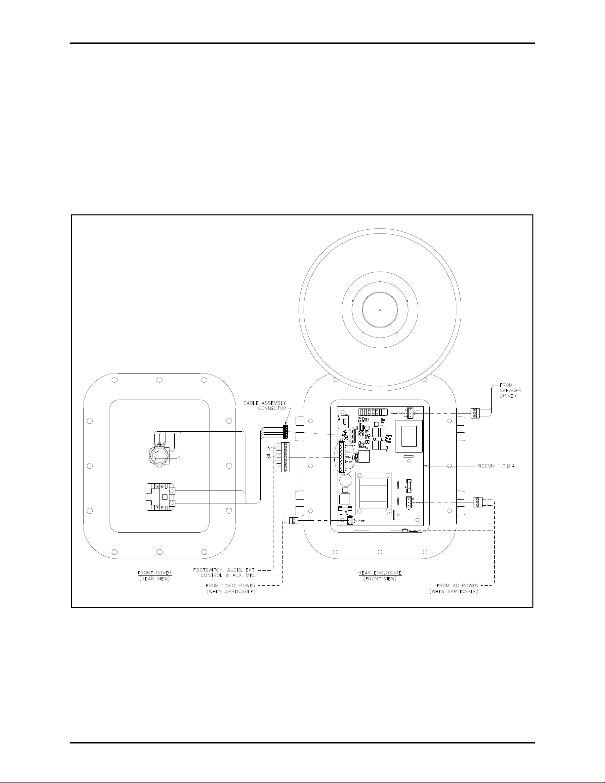
11. Plug all of the connectors into the new PCBA. See Figure 1.
12. Plug the cable assembly connector from the front cover into the PCBA in the rear enclosure.
13. Close the front cover and screw the 12 bolts back into the enclosure. The recommended torque
setting for the cover bolts is 17 ft-lbs (23 N-m).
Figure 1. PCBA Replacement Diagram
OTES:
N
1. Either 120 V ac power or 12 V dc may be connected to the Model 400-003 RigCom. Under no
circumstances should ac and dc power be connected to the Model 400-003 at the same time.
2. Either 230 V ac power or 12 V dc may be connected to the Model 400-004 RigCom. Under no
circumstances should ac and dc power be connected to the Model 400-004 at the same time.
e:\standard ioms - current release\42003 kit manuals\420 03-214b.doc
04/14
Page 3

Warranty
Equipment. GAI-Tronics warrants for a period of one (1) year from the date of shipment, that any
GAI-Tronics equipment supplied hereunder shall be free of defects in material and workmanship, shall
comply with the then-current product specifications and product literature, and if applicable, shall be fit
for the purpose specified in the agreed-upon quotation or proposal document. If (a) Seller’s goods prove
to be defective in workmanship and/or material under normal and proper usage, or unfit for the purpose
specified and agreed upon, and (b) Buyer’s claim is made within the warranty period set forth above,
Buyer may return such goods to GAI-Tronics’ nearest depot repair facility, freight prepaid, at which time
they will be repaired or replaced, at Seller’s option, without charge to Buyer. Repair or replacement shall
be Buyer’s sole and exclusive remedy. The warranty period on any repaired or replacement equipment
shall be the greater of the ninety (90) day repair warranty or one (1) year from the date the original
equipment was shipped. In no event shall GAI-Tronics warranty obligations with respect to equipment
exceed 100% of the total cost of the equipment supplied hereunder. Buyer may also be entitled to the
manufacturer’s warranty on any third-party goods supplied by GAI-Tronics hereunder. The applicability
of any such third-party warranty will be determined by GAI-Tronics.
Services. Any services GAI-Tronics provides hereunder, whether directly or through subcontractors,
shall be performed in accordance with the standard of care with which such services are normally
provided in the industry. If the services fail to meet the applicable industry standard, GAI-Tronics will
re-perform such services at no cost to buyer to correct said deficiency to Company's satisfaction provided
any and all issues are identified prior to the demobilization of the Contractor’s personnel from the work
site. Re-performance of services shall be Buyer’s sole and exclusive remedy, and in no event shall GAITronics warranty obligations with respect to services exceed 100% of the total cost of the services
provided hereunder.
Warranty Periods. Every claim by Buyer alleging a defect in the goods and/or services provided
hereunder shall be deemed waived unless such claim is made in writing within the applicable warranty
periods as set forth above. Provided, however, that if the defect complained of is latent and not
discoverable within the above warranty periods, every claim arising on account of such latent defect shall
be deemed waived unless it is made in writing within a reasonable time after such latent defect is or
should have been discovered by Buyer.
Limitations / Exclusions. The warranties herein shall not apply to, and GAI-Tronics shall not be
responsible for, any damage to the goods or failure of the services supplied hereunder, to the extent
caused by Buyer’s neglect, failure to follow operational and maintenance procedures provided with the
equipment, or the use of technicians not specifically authorized by GAI-Tronics to maintain or service the
equipment. THE WARRANTIES AND REMEDIES CONTAINED HEREIN ARE IN LIEU OF AND
EXCLUDE ALL OTHER WARRANTIES AND REMEDIES, WHETHER EXPRESS OR IMPLIED BY
OPERATION OF LAW OR OTHERWISE, INCLUDING ANY WARRANTIES OF
MERCHANTABILITY OR FITNESS FOR A PARTICULAR PURPOSE.
Return Policy
If the equipment requires service, contact your Regional Service Center for a return authorization number
(RA#). Equipment should be shipped prepaid to GAI-Tronics with a return authorization number and a
purchase order number. If the equipment is under warranty, repairs or a replacement will be made in
accordance with the warranty policy set forth above. Please include a written explanation of all defects to
assist our technicians in their troubleshooting efforts.
Call 800-492-1212 (inside the USA) or 610-777-1374 (outside the USA) for help identifying the
Regional Service Center closest to you.
(Rev. 10/06)
 Loading...